levon
-
Posts
114 -
Joined
-
Last visited
Content Type
Profiles
Forums
Blogs
Gallery
Everything posted by levon
-
ok, some progress on this, but still need a bit of guidance. my friend helped me put together this code, calling the pins directly. ADCON1bits.PCFG = 0xF; //OR //Set which ports are analog and digital //currently an0 = analog rest are digital ADCON1bits.PCFG0 = 1; ADCON1bits.PCFG1 = 1; ADCON1bits.PCFG2 = 1; ADCON1bits.PCFG3 = 1; //Set ANO as the analog channel to do the read from ADCON0bits.CHS0 = 0; ADCON0bits.CHS0 = 0; ADCON0bits.CHS0 = 0; //VRef+/an2 = VDD = 5v //vref-/an3 = vss = gnd //an0 = analog in //an1,4,5,6,7 can be digitial IO, as they are digital //they are referred to as RA0/RA1 etc //Turn on adc ADCON0bits.ADON = 1; //wait for adc to do conversion while (AD1CON1bits.DONE == 0) { continue; } int result = ADRESL | (ADRESH << 8); //turn off adc I've put this in the main loop, have AIN_unmuxed() and it all compiles fine. When i upload it to the midibox it will turn on, and then crash and restart about 5 seconds later. Have i missed anything in turning off the MOIS AIN functions? cheers
-
Thanks for both of your replies. ive been reading the datasheet alot, and i dont think it is possible with a 18f452 to do what i want. assigning the pins to analog and digital can only be done in a specific order, and does not allow me to switch between the two different order of pins i need. sigh.... i have however found these to tutorials on getting them working with an arduino http://kalshagar.wikispaces.com/Arduino+and+a+Nintendo+DS+touch+screen and AVR not running Arduino. http://www.sparkfun.com/commerce/tutorial_info.php?tutorials_id=139 lylehaze i think the Transistor way might be the easiest... though i understand how transistors work... im not sure how i would design a circuit to do the job. im not sure if im on the right track here.... but i think i need to do the following. use one transistor connected to a Dout pin, one to ground and the other to the AIN pin... then when the Dout pin is high, it will connect the AIN pin to GND, when Dout is low, it will be 5V+ right? then basically have 2 of these, and in code i can set Dout0 to high, Dout1 to low... read the X value... store it, switch the Dout pins....read the Y value. or is there an easier way of doing it? thanks for all your info though, ive spend weeks reading up on ASM, its been... er... fun. :P
-
No sure if this should be here, or in the ASM section.... anyways. in trying to get this xy pad working, i need to switch the assignment of some pins. to measure the X axis i need to assign the pins as such. Pin 1: 5v+ Pin 2: d/c Pin 3: Analog in Pin 4: GND and the Y axis Pin 1: Analog in Pin 2: GND Pin 3: 5v+ Pin 4: d/c im assuming this has to be done in assembler, but i cant for the life of me figure out how to do this. if anyone could point me in the right direction, would be great. I have plenty of free pins of the J5A/B port on the Midibox core to use. so basically i just need to use A0-A3 of the J5 port, and assign A0 5v+ and Analog in A1 unassigned and GND A2 Analog in and 5v+ A3 GND and unassigned. 1. can this be done in C, or does it have to be done in assembler? 2, any hint at what functions can assign a pin to be analog in... GND, and 5v+ cheers, this has been doing my head in for a few days.
-
All three were 52 + GST in total, but laser 3d have a minimum invoice of $75 + GST, so i could have had a 4th panel cut out and paid the same, but didnt have anything else. the other 4 companies i got quotes from were around $160-$190.
-
its a stupid English saying
-
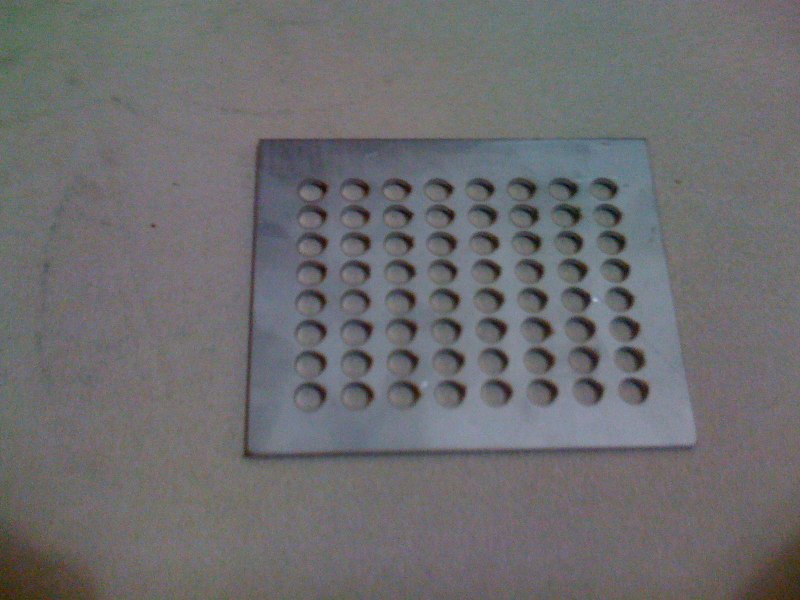
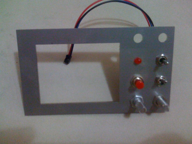
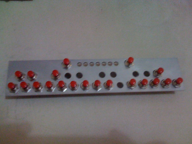
I just got my 3 panels i had laser cut, im quite happy with them :) material is 2mm Stainless Steel. first is for an 8x8 LED matrix. second is the frame for a nintendo DS touch screen, and some switches, encoders etc. third is a 2 octave keyboard with octave +/- function, and leds. I'll post more details about this project later, im still working on the MOIS App and the case for the midibox. The panels were laser cut at laser 3d I cant recommend them enough, their service was great, and the price was less than half the price of any other quote i got. They have workshops in Adelaide, Sydney and Melbourne, Australia.
-
Im currently putting a midi system into my guitar. i decided to go for the graphtech ghost saddles, with the hexaphonic expander and the acoustic expander It is more expensive than the Roland and axon midi pickups, but it has the added benefit of also having an acoustic(whats that??? i hear alot of you saying) piezo sound, and also all the equipment is barely visible. then ill get an axon midi converter, not sure if ill get the AX-100 or the AX-50 yet. Still a while off being finished, but im hoping after its all done to build a SID to control from my guitar.
-
doh, your right... why are there so many different specs! *starts the hunt again*
-
I found them cheaply... http://www.futurlec.com/SMD_Adapters.shtml The 8 pin one should do the trick, i can just cut it in half. And YES i will add it to the wiki when i document my project, after its done. :)
-
Im working on a touch screen midibox using the nintendo DS x/y pad. and using the Touchscreen connector. which is ment for Surface mounting. I've tried soldering wires to the pins, but they are too close together. What I need is a small PCB the connector can be soldered to, that connect to 4 SIL Pins. but i have no idea how i could make this... would etching be precise enough for the surface mount component? anyone have any other ideas?
-
Thanks julienvoirin, looking though your code has helped, just need to build my 8x8 matrix so i can test it :P
-
I got one of these DS touchscreens, just need the time to test it, I'll get back in about a week if it is any good
-
I'm on my iPhone.... Could you post the YouTube link?
-
Can the BLM driver be used with the AC-Sim? ive been trying to get it working, with no luck. Also it seems that DOUT_SetPin(); doesnt work with AC-sim. anyway... Im building the matrix next week and just wanted to make sure Im doing it right before i start. The Cathodes of the LEDs will be connected verticaly in colums 1,2,3,4,5,6,7,8. these will be connected to J5 of a DOUT module ( pins 0-7) The Anodes of the LEDs, will be connected horizontaly in rows 1-8 and connected to J6 of a Dout (pins 0-7) Im just not sure as http://www.ucapps.de/mbhp/button_duoled_matrix.pdfm has some of the buttons connected to the Dout Cathodes. If I set it up like that in an 8x8 rather than a 4x16, will the scrambling discribed in this link be a problem, or can it be changed in software? im fairly sure it will all be fine, but i just wanted to check so im not wasting time. thanks
-
From what I understand 2 of the lines are supplied with 5v and the other 2 will have a resistance one for the x, one for the y. I havn't had time to test it yet to see what the resistance is, if it's 0-10k ( I hope) then it should just go into 2 AIN pins.
-
Thanks TK, you rock. Ill have a look into the BLM code. since im using just a single led 8x8 matrix, i can do this with just 2 Shift Registers. J5 and J6 of the DINx4 board. Is there much difference between the Mios32 and MIOS? how much code will need changing? Looks like ill skip the dimming LEDs, but would it be possible to flash them, say once a second?
-
I'm starting to design a new project, basicaly a 8x8 matrix. But I'm a little confused as to what way to go about it. I want to have a single coloured 8x8 led matrix and I will be programming in C. It will have a core, 1 4xDIN module (28 buttons, 2 encoders) 2-4 pots connected directly to j5 of the core. And 1 4xDOUT. For the core I will have 8 red/green leds connected to the first two multiplexers. For the third and fouth multiplexers I wanted to use as a 8x8 led matrix, using J5 of the DOUT board for the anodes of the matrix, and J6 for the cathodes. I found a diagram on using this for the midibox 64e with led rings. Now I'm not sure if I should try to used the blm driver, the 64e software, SID or code it myself, as the availlable drivers have features that I don't require, and I don't know asm to customize them. Are there any C examples of an 8x8 matrix already? Is C fast enough to do a matrix? I'm having a bit of trouble getting my head around how the matrix works, but I would basicaly like to be able to control each led in the matrix individualy. Also, would I be able to control the brightness of the LEDs individualy by flashing them very quicky at different intervals in the led matrix? Thanks
-
I just got a nintendo ds touchscreen ( check out sparkfun, I can't post the link cause I'm on my iPhone) I'm yet to try it out, but for $10 it might be a good x/y pad for midiboxes. Sparkfun says you run 5V across 2 pins, then by reading the other 2 pins you get an x and y voltage. I'll let you know how I go.
-
Pm's have been sent, please reply ASAP, so i can order parts.
-
Sorry bout the delay, ill be sending out PMs in the next 48 hours with total costs.
-
sorry, Australian parts order wont happen for another week, im so busy with filming and editing i dont have any time to sit down and organize this until Monday next week. will contact everyone by PM next week. ,Levon
-
I am organizing a bulk buy of parts for the GM5 USB-MIDI interface for people who already have their chips and boards, or are on the waiting list to get them. I think most people already have added their names, but just incase some people havnt seen it in the main GM5 thread please post your name and quantity of parts needed on this page http://www.midibox.org/dokuwiki/tk_gm5_jaycar_partlist I will be locking off the list on Tuesday the 11th of November, and PMing everyone with prices. Thanks
-
Ok, so Styrd is waiting for the next batch of GM5 chips before ordering parts. So I will be doing the bulk buy, im going to buy some parts from Jaycar and other parts from Rockby to get the price a bit cheaper. im gonna do some spreadsheeting and work out the final cost, it would be easier if people could pay directly into my bank account, but if i have to i can accept PayPal. and ill need everyone paid up before i can order. Ill send out a PM to everyone on this page on the weekend and we can get things started. cheers, Levon
-
Me and Stryd were organising that, but i havent heard back from stryd for a while ***** Stryd, check your Messages*****
-
YAY, i just received my 5 boards and 5 chips in the mail... damn the chips are small, better start practicing before i attempt the real chips. Thanks TK and wilba for all your work