EvilEvilEvil
-
Posts
49 -
Joined
-
Last visited
-
Days Won
1
Content Type
Profiles
Forums
Blogs
Gallery
Everything posted by EvilEvilEvil
-
Displays not initializing after working for a while
EvilEvilEvil replied to EvilEvilEvil's topic in MIDIbox SEQ
Hey TK - thanks for joining in! Yes, I am only running the pin tester with the display disconnected. Now that I hooked up the LCD, the error is gone! But still nothing from the display :( -
Displays not initializing after working for a while
EvilEvilEvil replied to EvilEvilEvil's topic in MIDIbox SEQ
Mouser It's an MB997D I never did the firmware update but I assume that's not a problem. It was working fine before. -
Displays not initializing after working for a while
EvilEvilEvil replied to EvilEvilEvil's topic in MIDIbox SEQ
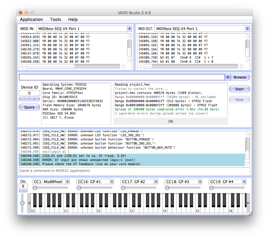
OK - here's a quick update. When I run "testlcdpin d1 0" I get "D7 input pin shows unexpected logic-1 level" And "Please check the D7 feedback line of your Core Module" I am measuring 4.86V at pin D7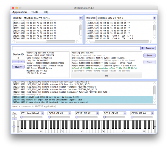
-
Displays not initializing after working for a while
EvilEvilEvil replied to EvilEvilEvil's topic in MIDIbox SEQ
I tried 2 new shift registers. Still blocks. Really can't figure this one out... :( -
Displays not initializing after working for a while
EvilEvilEvil replied to EvilEvilEvil's topic in MIDIbox SEQ
Just ordered more shift registers. Think that reuploading the bootloader might help? -
Displays not initializing after working for a while
EvilEvilEvil replied to EvilEvilEvil's topic in MIDIbox SEQ
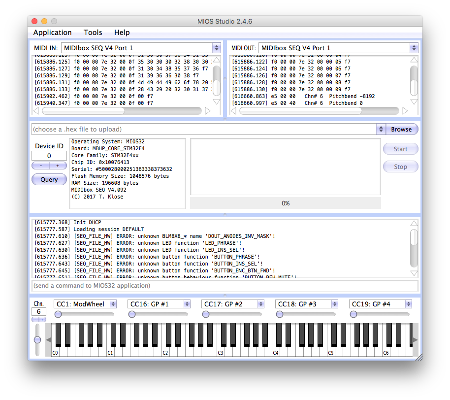
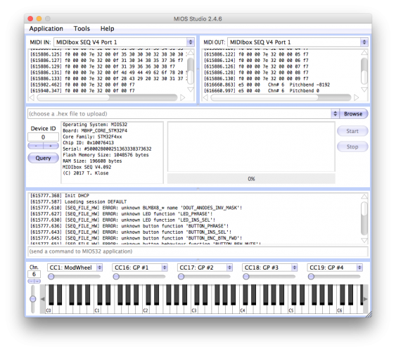
• Previously it worked fine before with just 1 LCD • Loaded up MB_NG and get an error "no response from CLCD". See attached - perhaps this is a step in the right direction. For the ribbon cables I followed the wiring 1->15 2->16 and so on... Again, it worked fine up until now so not sure what could have happened. • Reflowed the joints • The scratch was just a smudge - I rubbed it away. • I tried many 5v options and both usb ports Thanks all for the help so far! Much appreciated... EDIT: The resistor array is 1k Ohm - I know others had this problem because they accidentally used 10k. EDIT 2: I downloaded the MIDI 2x2 program and the MIDI i/o modules work fine with it. Not sure what this proves but perhaps we can cross out the possibility of some faulty components? -
Displays not initializing after working for a while
EvilEvilEvil replied to EvilEvilEvil's topic in MIDIbox SEQ
Here are the pics. I do not have another shift register to test with atm. https://www.dropbox.com/s/0sjsstrz42t68ja/1.jpg?dl=0 https://www.dropbox.com/s/vjkdq31xcx9wtkx/2.jpg?dl=0 https://www.dropbox.com/s/9k8o3szcungkhxx/3.jpg?dl=0 https://www.dropbox.com/s/1vaz7nhafxn1m5y/IMG-3078.JPG?dl=0 https://www.dropbox.com/s/tjbm15s41sy59cf/IMG-3079.JPG?dl=0 https://www.dropbox.com/s/vcn79o98kpq3zr2/IMG-3080.JPG?dl=0 let me consolidate all the info • The Core and LCD worked fine for several weeks while I awaited parts to build the MIDI I/O and CS • I built the MIDI I/O and tested it with MIOS Studio - no problems • After building the CS I plugged it in and transferred the MBSEQ_HW.V4 file to an SD card • turned it on and only have squares on LCD, MIOS studio reports that Seq V4 is installed • Unplugged the CS - still squares • Removed the SD card - still squares • Tried another LCD - still squares • Tried another ribbon cable - still squares. • Tried other 5v power supplies - still squares • Adjusted brightness/contrast - still squares • Wife is getting upset - still squares • Have to pick the kids up - still squares • Going to sleep last night - still squares.... -
Displays not initializing after working for a while
EvilEvilEvil replied to EvilEvilEvil's topic in MIDIbox SEQ
Yeah, barebones - just core, and 1 lcd. -
Displays not initializing after working for a while
EvilEvilEvil replied to EvilEvilEvil's topic in MIDIbox SEQ
Yes, I tweaked both the brightness and contrast. I tried another display and a new ribbon cable - still nothing. I checked all my solder points to see if anything came loose, checked for debris that might cause a short. At a loss here as it was loading up to the default screen for weeks until I hooked up the CS. Before, I never had the SD card inserted and this time I inserted it with the MBSEQ_HW.V4 file in the root directory. But even when I take the SD card out now the display still shows squares. Could something have been affected by the SD card? -
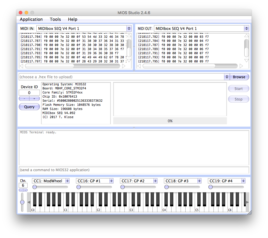
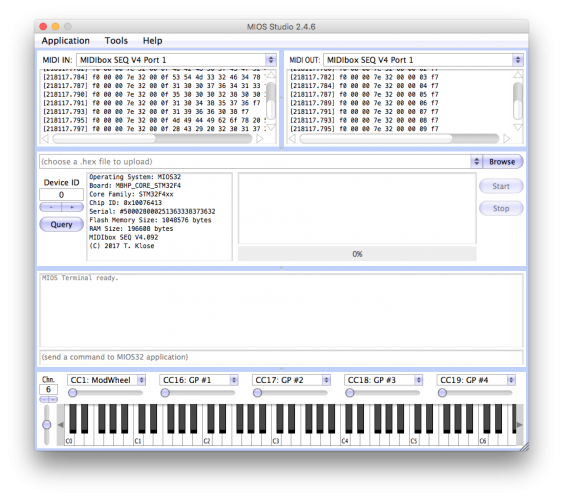
My displays were loading up fine the past few weeks when I just had them plugged into the core with the MIDI I/O mods attached. Today I finished up the wilba CS and plugged it into the Core, restarted the Core with the MBSEQ_HW.V4 file in the SD card and now I just get those bars/squares on the LCD when I plug it in. Even when the CS is removed and I go back to barebones Core and one LCD, there is nothing but the black squares. Been troubleshooting for hours. Didn't change anything on the core. i even made a new ribbon cable thinking that something was wrong there. MIOS Studio seems fine (see attached). Any suggestions? Thanks.
-
Now that all my modules are almost finished I'm not sure if I want to use a case at first. I love the raw, punk rock look of it. I'm thinking of just mounting everything with standoffs on acrylic. Has anyone else done this? If so how do you label the controls? And do you think the electrical components will deteriorate this way (dust, etc)?
-
Thanks. That worked!
-
I'm in OSX and the driver originally said "MIOS32" but after deleting that I now get 4 ports that say "MIDIBOX SEQ V4" which I assume is correct. If I choose those ports in MIOS studio and play the virtual keyboard, shouldn't the activity lights on my MIDI I/O light up? Or am I missing a step?
-
I have the core/lcd and MIDI i/o modules all built and running. Is there a way to test the MIDI i/o modules from the MIOS studio virtual keyboard?
-
Anyone? Tumbleweeds?
-
Hi, Do I need to have a PIC burner for the MBHP_IIC_MIDI firmware? I got my Core up and running via terminal in OSX - just wondering if there's an updated way to do something similar with the MBHP_IIC_MIDI (perhaps via the Core)? Thanks
-
I have a dual voltage transformer here that delivers 5 & 12 Volts. Would it be possible to use these (12 instead of 14?)
-
I just went out and got a digital multimeter to see if there was anything. it reads 2v AC. What could the problem be?
-
Yeah. NADA. ???
-
Getting started with my midisid, trouble re-using c64 power supply
EvilEvilEvil replied to cchocjr's topic in MIDIbox SID
I'm not getting ANY volatge out of my AC pins! NOOB HERE TOO. I set my multimeter to ~50V, nothing. 5v DC works fine though. I am testing them by putting the multimeter pins against the AC pins. Any suggestions? -
I also just unpluged the power cable from the PSU and tested the pins. the DC works fine. The 2 AC pins are getting no reading? Any suggestions? I switched my multimeter to 50V~ for the measurement. Thanks
-
Doing the optimized PSU. I have all the parts together. and -5/5V coming out of the correct pins. But I cannot find the AC current. my multimeter is set to AC but I still cannot find the right pins???
-
Yes! that's what I'm referring to. So I can just use different caps that add up to that value? What about the bridge rectifier? I don't have one of those but the "shack" down the street has a bunch. But they are value marked and not part number marked. Is there a different one I can use, or do I HAVE to use that particular one? What values am i looking for? Thanks!
-
Is there a different capacitor i can use for this? a different value? I just don't have one of these laying around. can i use any of the caps in the C64? What happens if i use a different value? bad things? evil things?