

matoz
-
Posts
302 -
Joined
-
Last visited
Content Type
Profiles
Forums
Blogs
Gallery
Posts posted by matoz
-
-
i am building a MB64e and i am confused, the controler take encoders as buttons.
i have 2 din modules, in the first one there is 8 navigation buttons witch are working and in the second (chained to the first) there are 15 encoders witch are scanned as buttons. what could be the problem.
in http://www.ucapps.de/mbhp/mbhp_dinx4_16enc.pdf ,in the schematic, the encoder din module is on J6, but the note below the schematic says it must be chained to din button module at J9. Is there a problem of interpretation?
With mb16e application, when enc din module is at J6, encoders are not recognized, nothing happen when i turn encoders
When enc din module is chained to button din module, encoders are recognized as 2 buttons.
Thanks
Loic
-
I sell 4 sid 8580, asking 100€ shipping included
and 2 6581 , asking 40€ shipping included.
Pm me
Loic
-
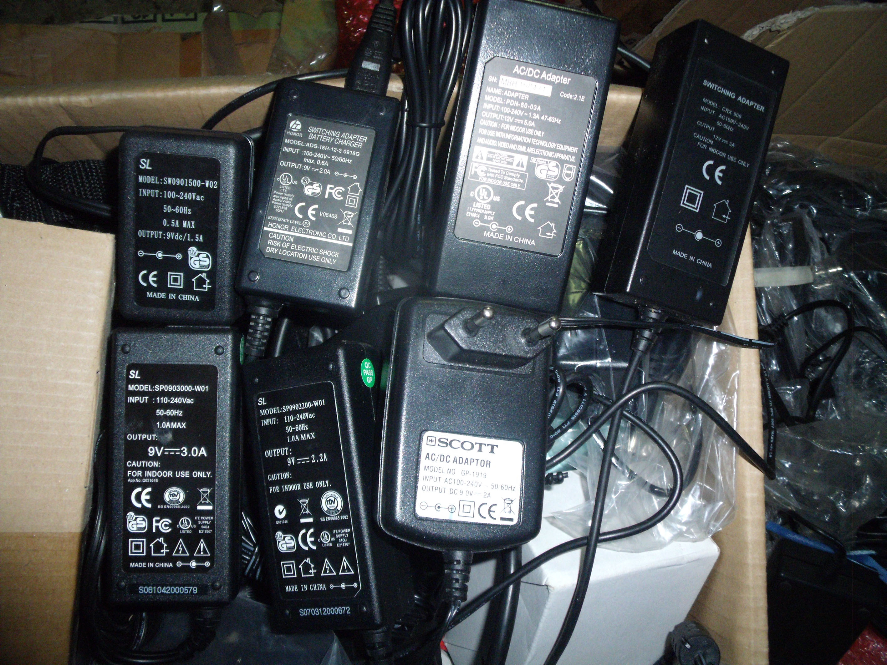
I have a lot of PSU to sell with good prices:
100-240/5Vdc 1,5A : 3€ W150g
100-240/9Vdc 1,5A : 4€ W200g
100-240/9Vdc 2A / 2,2A : 4,5€ W250g
100-240/9Vdc 3A : 5€ W250g
100-240/12Vdc 3A : 5,5€ W400g
100-240/12Vdc 5A : 6€ W400g
SHIPPING EUROPE in strong letter:
150>299g : 4,1€
300>599g : 6,1€
600>999g : 8,75€
1000>2000g: 12,6€

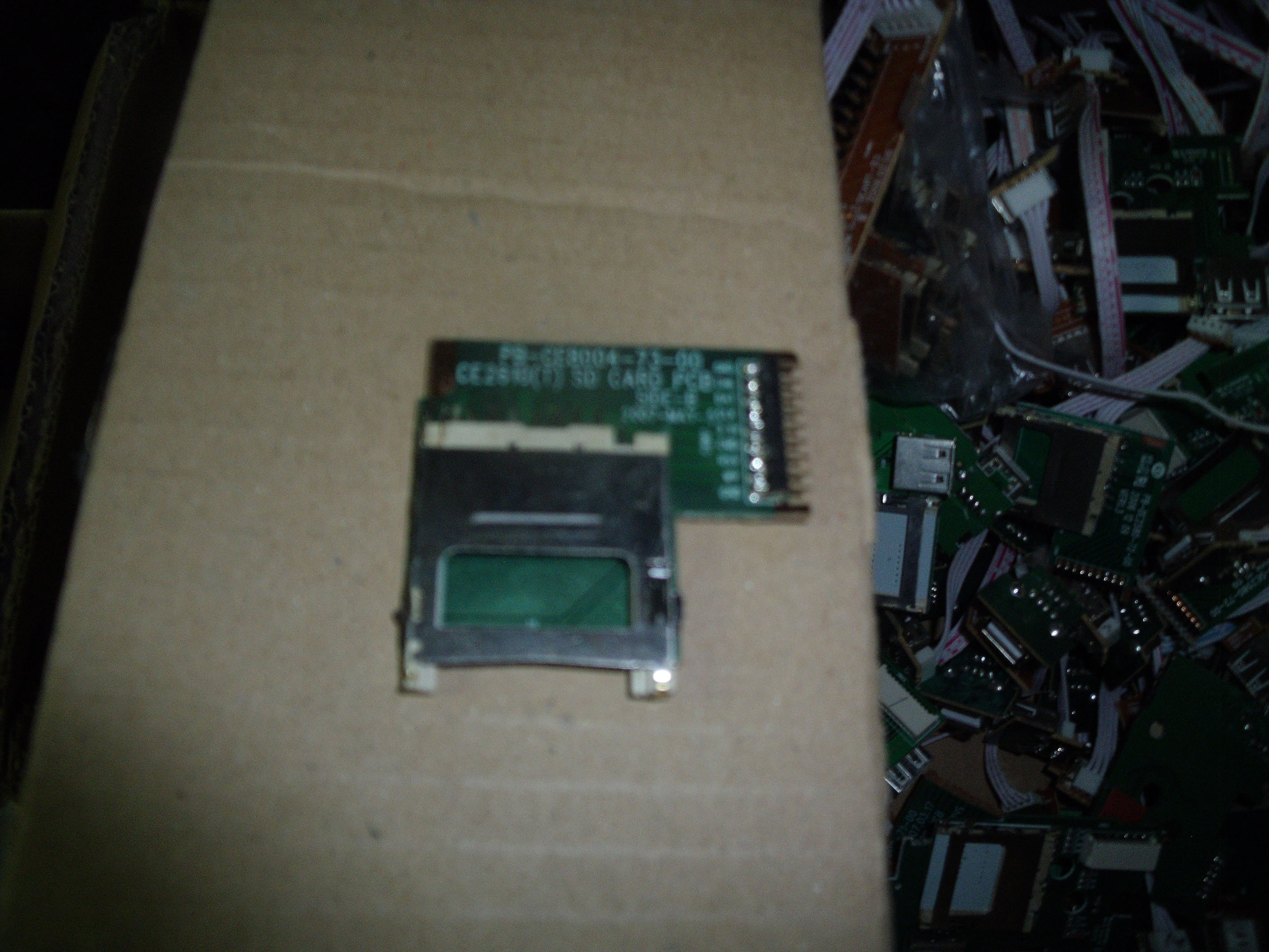
And I have a lot of SD card reader, i will give them for free with psu:

If interested, please send me a PM in this way:
Name
Adress
Postal Code
Country
The psu you want and the number
Your Paypal Adress where i will send a request.
-
I'm terribly sorry, i didn't thought it would be a problem. But i understand very well.
Can you delete the post or should i modify the first post?
-
done, thanks
-
I have to sell 2 Shruthi-1 cem 3379 filter in white box (4Pôles box) with 9v 1,5A psu: http://cgi.ebay.fr/SHRUTHI-1-CEM-3379-ANALOG-FILTER-/180991876066?pt=FR_YO_InstrumentsMusique_DJSONOSTUDIO_DJ_Sono_Studio&hash=item2a23f4dbe2
And 1 Shruti cem 3379 filter (original first design) in a diy paper box with 9v 1,5A psu : http://cgi.ebay.fr/SHRUTI-1-CEM-3379-ANALOG-FILTER-FIRST-ORIGINAL-COLLECTOR-DESIGN-/180991880341?pt=FR_YO_InstrumentsMusique_DJSONOSTUDIO_DJ_Sono_Studio&hash=item2a23f4ec95
-
the mios seem to be in the lpc board.
Did you try to upload sevV4 application with mios studio?
For LCD, did you check P1 an P2 (luminance and contrast of the LCD)?
If it does nothing, you will have to check connections with the datasheet of the LCD.
-
Hi Doug, some news?
Have you received PCB's?
best regards
Loic
-
i uploaded the last release and it works.
Thanks
-
problem to recompile V2.039, it's me? see screen print
-
i tried to check it with mios studio, when i turn encoders there is no data into mios studio midi in.
Perhaps i have a connection problem but i don't think, because when i upload application mios studio receive datas. With the same connection, when i turn encoders there is nothing. Perhaps a Guru could light us?
-
yes, it doesn't work.
Filter cutoff works on CV5-7, but there is no resonance. And when i touch filter cutoff on CV5-7, it disable filter in channel 1.
Is there a way of sending CC from MBSID?I didn't knew MBSID doesn't send CC to midi out.
It will be a problem for my project because i wanted to record all cc parameters played in live in Cubase or Logic... :-(
It is very strange!
-
and if i modify the firmware for the core 2 , i disable V2A, P2A, K2A and O2A (all settings to 0), i could assign F2A to Aout 5,6,7,8? and i wire J6 core2 to J1 Aout NG at the same time J6 core1 ?
-
y a une case à cocher dans un des menus pour que le mouvement du potard ne soit effectif que lorsque tu repasses par la position
Merci pour la bonne nouvelle!!
-
"The SID doesn't control the VCFs, that's done by the 4 core modules. Env and VCF data is local to each core (no, it's not shared from a "master" CPU via CAN) so you'll need one AOUT_NG per core if you want the full custom shine. AFAIK the AOUT_NG is connected using I2C SPI to the core, I don't think that's set up as a multi master bus as is. Perhaps TK, Wilba or one of the guru's can tell us if that will change later down the road?
The connection is: Core -> SID, Core -> Aout, SID Audio -> VCF/VCA, AOUT CV -> VCF/VCA. Plus control bits as necessary using the available port headers at each core."
If i understand well, to run my second ssm2044pcb on channel 2, i would need a second aout NG on core2?
Isn't it possible to use CV5>CV8 of first Aout NG wired on core1 to control my second SSM2044 PCB from channel 2?
What about using MBCV to control 2 SSM2044 pcb with only one aout NG by midi (channel 1>CV1234 and channel 2>CV5678)?
So adding one core add less cost than adding one AoutNG...
-
yeah!!! it works, the LED blinks three times
and then goes off and then comes on and stays on , i think it is ok.
In File, i selected New, other, selected LPCXpresso C project, select wizzard C project, named it "test", select target selection LPC1769, and select None in CMSIS options, and it create a project on project window at the left, and after that i was be able to click on the icon program flash, i browse the project.bin and click OK, and it has been done.
-
Some news, i have the file project.bin into the project window, and when i click on the icon program flash, it says: "project project has no MCU information"
No problem with the file project.hex, i can be opened, but i didn't found yet how to send it into the board.
-
Hi all,
i can't load mios32 bootloader, when i click on the icon "program flash", there is nothing inside the box.
When i try to open project.bin, computer says it isn't a valid Win32 application.
Any idea?
-
Pour la position 0 à midi, ce n'est pas un problème, chaque paramètre est configurable dans la MB64e sans programmation, pour chaque contrôle, tu peux éditer la valeur minimum et la valeur maximum, dans ce cas, tu vas mettre -64 pour le min et +64 pour le maxi, comme ça, ton 0 sera au milieu de tes valeurs extrêmes.
-
non, pourquoi?
Je n'utilises plus d'ordinateur pour faire de la musique depuis un moment et je m'en porte très bien :-)
Fini les plantages de carte son où autre en plein milieu de la prestation...
Mais j'ai vu Logic à l'oeuvre chez un pote, et effectivement il est très complet au niveau midi.
J'ai parlé de ton projet à un pote qui utilises ableton, et il m' a dit qu'un fois qu'un contrôle est assigné à un contrôleur, tu peux le sauvegarder et tu n'as plus à le refaire à chaque fois.
-
Doug, please, give us some news.
No update on your site since december..
Have you received PCB's? what is the status of this very long project?
-
une fois que le mapping est réalisé, tu sauvegardes dans ton logiciel et dans ton contrôleur et tu n'y reviens plus.
question1: je ne connais pas assez ableton pour te répondre
question2: l'usb fournit bien 5v mais je ne sais pas quelle est l'intensité fournie par l'usb de ton ordinateur. Si tu mets un écran LCD, ce que je te conseilles pour le paramétrage de tes contrôleurs, il te faut au moins 500mA.
cherches dans le forum sur ce sujet pour voir ce qu'en disent les autres.
question3: pot=potentiomètre= résistance variable=contrôle analogique= bouton qui a un début et une fin, c'est à dire que si tu utilises un pot pour plusieurs paramètres, ce que tu comptes faire, tu auras des problèmes de rappel de position par rapport à la donnée actuelle, ce qui ne sera pas très fluide et risque de faire des chocs de données.
(exemple tu tournes ton pot jusqu'à une valeur de 90 puis tu changes de page pour éditer un autre paramètre qui lui est resté à 10, dès que tu vas toucher ton pot, la valeur va passer d'un coup de 10 à 90....)
encodeur: lui, il tourne à l'infini, et convient parfaitement pour être utilisé pour plusieurs paramètres. pas de problème de choc de données, il incrémentera et décrémentera les valeurs à partir de l'endroit où tu les as laissées.
-
Je ne connais pas très bien Ableton, mais dans ce que j'ai compris, je pense que ton projet devrait être réalisable.
Dans ton exemple, tu aurais besoin de 12 encodeurs et 6 boutons = 18 cc.
Dans les midibox 64 et 64e, tu as plusieurs pages (ensembles virtuels d'encodeurs) qui serviront à contrôler tes plug ins. Il suffit de mapper les 18 premiers cc sur les plugins de ta première piste, les 18 suivants sur le 2ème ext...
Si c'est pour 10 pistes, cela veut dire que tu as besoin de 180 cc. Sachant que dans un canal il n'y en a que 128, il fa falloir que tu répartisse tes cc sur des canaux différents, ce qui est faisable dans ableton si mes souvenirs sont bons.
-
tu as réglé le contraste de l'écran avec les resistances variables qui sont sur le pic? je crois que le contaste est trop fort, ce qui explique que tu as des carrés pleins à la place des caractères.


encoders recognized as buttons
in MIDIbox HUIs
Posted
Thanks for your answer Altitude, i knew that. But in Mb16e, encoders were not in their menu. they were on buttons. I've just found my problem, the enc din was not connected correctly on but din (on core J9). Yesterday, it took to me about 3-4 hours to search, test and more... And this evening, i tryed to connect them and it works good. I thought i made a mistake when i connected them because it was the other connection direction i tried an verified yesterday, but i tried to power it to look what it do, and it is my solution!! :-) The "tomorrow chance" :-)
It doesn't explain why in the schematic enc din is connected to J6.
Good adventure!
Thanks, bye