mr_DK
-
Posts
48 -
Joined
-
Last visited
Content Type
Profiles
Forums
Blogs
Gallery
Everything posted by mr_DK
-
A driver is an implemented piece of code which is used by MIOS to use special functions like GLCDs or other special components. To be honest, people here are really precise, they know exactly what the whole MidiBox project is about. Only for you it's very difficult to help because you're new here and you want to create a huge project which has no design tutorials online and I think you don't really know what you want for yourself. Always remember that people like stryd_one and TK are the big V8 engines behind this whole project, they know every detail from hardware to software! The only thing you need to do more in my opinion (it's just advice, do with it whatever you want) is to read and get to know what you want to build: What I think is that you want to build a "controller" for Ableton which is a DAW. There are already many premade mixing consoles on the market which do these things (some things you should really know when you want to work with MIDI to control audio software) Have a look at the following website: http://www.mackie.com/products/mcupro/index.html http://www.euphonix.com This is the famous Mackie control about which I was talking, it looks like your Behringer controller but some more control functions. It's this one that is emulated with the Midibox LC. I guess you want to end up building a console like a Euphonix or something which is possible when you add some more encoders to the project. But the MBLC is a good start to get to know the midibox system and afterwards you can expand like your wishes are. This is the last time I will talk about these damn pots, always remember when you use pots and not encoders, when you open a file in ableton, your pots just won't adjust to the value your current FX preset has!! That's why encoders are so important, when you open a preset like for EQing in your ableton, I hope you wish that the console takes over the same values? Well, with pots it simply can't... They stay as they are and the computer cannot change the values. I guess stryd_one is right, you ask for help but you already made your mind up about what you want.
-
Don't forget that with pots you can't use bidirectional communication with your PC, the PC is not capable of changing the value of a pot (unless it's motorized) That's why encoders come in handy. I think youre trying to create a digital console? You might have a look at the MBLC project which is an emulation of a mackie control. I'm building one of these myself but also with some more encoders because one is really like not much. I know what stryd_one is trying to say, don't make it to big from the first day, just start with like 4 encoders (or pots) and try if you can get them programmed and at some more time by time. (the way I usually work)
-
Hi julienb, I'm not such a specialist myself but I try to help you were I can: 100 Buttons, no problem you can handle 128 buttons with one core (using 4 DIN modules) 100 knobs, are it encoders or analog pots? Because on a standard core you can only connect 64 encoder (when they don't have a push function which would need another input off course) So you need already 2 cores to handle the 100 encoders. Also with pots (AIN modules) you can only connect 64 to one core. 50 rgb LEDS, this will probably be the "hard" part, as far as I know you have two options, you can use DOUT modules which gives you the standard 8 color options, or you must connect them to an AOUT module to create all RGB colours. (It's just logical thinking, I'm not sure about this, someone please correct me if I'm wrong ;)) There are some assembly drivers on the forum, but none in C... There are some more discussions on the forum which handled RGB leds or duocoulored leds: http://www.midibox.org/forum/index.php/topic,10476.msg79410.html#msg79410 http://www.midibox.org/forum/index.php/topic,11541.0.html http://www.midibox.org/forum/index.php/topic,12748.0.html Here you can read more about connecting multiple cores: (I guess the feedback trouble is fixed) http://www.ucapps.de/midibox_link.html I guess you could try the midi128 or the MB64 but off course you will have to make some adaptations. I hope this was a bit helpfull... Regards Hans
-
Some good news at last! It works 8) your last ideas put me to do some new testing, I changed the PIC that was on the board with the one from my MBLC work. I uploaded the T6963 vertical project and it just worked. The old pic does work with CLCDs (tested it wit the srio_interconnections_test), but every time I upload the T6963 hex, I got this to bars on the GLCD about which we talked before. The versions of the two pic's are different: The old one has Mios bootstrap v1_2 on it (2006) The new one has mios V1.9F Can it be that there's a difference between the two loaders? because it's so strange that the one with the older version does work with CLCDs but not with the GLCD (I think it's not really broken...) And yet another question: Any hints on how to start editing the driver? Another big thanks for all the help you provided!! MidiBox rules :D Regards DSC_4272.JPG DSC_4272.JPG
-
Indeed picture in the wrong direction :P I send an e-mail tot the lcd-module.de contact and I got this answer: - wrong connection - cable longer than 10cm (it's 15cm here) - broken cable (checked the wiring a zilion times) - wrong power supply - wrong interface timing - missing GND - bad levels on bus (also trise and tfall times) For them this could be the reasons... thanks
-
Here's another picture of the wiring, I just checked the display without the external suply so there was no backlight and it seems that I don't have this snow particles. It could be that I need the place some condensors to "filter" the 5V line. I only see those two big vertical bars as you could see on the other picture. DSC_4252.JPG DSC_4252.JPG
-
First I'll answer yuour questions, I own the W240-7KHLW, so it needs 135mA. I did as you said to use an external power suply the 7805 was really hot (but did not burn myself 8)). I connected the anode and cathode from the LCD to the power suply, this works fine. Also the hex uploading works perfectly now! Only still no text... I added some pictures of the connections and the screen I got. It's like running things and two big bars. I double checked every pin and I'm pretty sure it's good now: LCDpin 19 and 15 are pulled down LCD pin 18 and 16 are pulled up all the other pins are just like you said before. cheers DSC_4248.JPG DSC_4248.JPG
-
I feel like some kind of dumbass, trying to walk while I still cannot just stand up. Last time I spent hours looking at books and tutorials how PIC ICs are programmed, and more and more I realise that the MidiBox project will take a long time for me to understand on "PIC" level. Before I can even try to program a driver myself although I'm really interested and I would really like to be able to write drivers myself and to contribute some more to the MidiBox project because it was a real revelation to me. Conclusion: if you get bored of my stupid questions, just tell... Anyway, some more questions: Is it possible that I'm unable to upload a hex file while the GLCD is connected? Miosstudio is giving me a lot of errors and then times out after 16 errors. When I disconnect the GLCD from the core, the uploading is done properly. The problem of adapting the old driver for my GLCD is just that I don't know where to begin, because the LCD is using the same controller and all the pins are connected the same way as a smaller LCD but it just don't display anything when I use the T6963 driver from the Mios Download page. It would be more logical (I guess ???) that it works, but just not uses the whole size of the LCD. When this was the case I would know where to start adapting the driver. Thanks agin for all your help! Philetylor, when I really don't get this working, would you like to have a look at it? I could send the LCD over to your place so you could do some testing with it yourself. I would of course respect it if you don't have time for this! ;)
-
To be honest I didn't missed it, read it a lot of times to be honest ;) I don't know why I descided to take this t6963, but I was planning on using a dedicated core for this GLCD to seperate the MIDI processing from the LCD processing. Quite difficult when it can be done in an easier way, I know... I didn't mention pin 18 and 19 because I thought they didn't really matter for the result a got, anyway here it is: I pulled pin 18 down and pin 19 up. I found a driver for the T6963 controller which should support alse the bigger displays: http://www.ccsinfo.com/forum/viewtopic.php?t=31255 I edited the bus data in the file so that the data bus is PortB and the pins of PortD which are used. I took J14 of the core for the reset connection as you can see. I implemented the driver into an SDCC skeleton. I added it to the post as an attachment. I only have a problem compiling the file with SDCC I got 1 error: T6963.c:29: syntax error: token -> 'TextHome'; column 23 I just don't know what this problem is... Again any help? ??? Thanks, Ciao t6963.c t6963.c
-
Hi, I tried to pull the enable pin down and the RST pin high. The LCD looked more stable because there were no lines crossing anymore. I loaded the T6963 vertical project from the MIOS download website but it gave no text on the screen. I think there are two possible reasons for this: 1* The driver isn't supporting an LCD this size, so I have to program a new driver. ? 2* There is still something wrong with the hardware setup. I read in the T6963 guides that this enable pin is pulled don when interfacing with the MCU, so I guess it can not be pulled down permanently. I was thinking of connecting it to J14 of the core. But also in this case I need to create a new driver. :D I guess I can never get this woking with just hardware changes, it needs some software adaptations as well. (Any more clues?) Thanks Cheers
-
Thanks for the replies, To be honest I looked at the resolution and the controller type as I bought it, I hoped that the resolution difference was just a matter of adjusting the driver... But so far I'll try the ideas you gave and look what it does and hopefully I can do some tribute to the Midibox forum.. (when I get it to work) ;) I just start by reading all the documentation about the T6963 controller (thanks for it philetaylor 8)), I like a challenge and I really hope my skills are good enough to fix this problem. I'll keep you informed, It's still just one hot LCD :P Cheers
-
Indeed it is, I only discovered the bulk order page of the GM 5x5x5 a week after I ordered my PCBS. Thanks for all the replies! 8) Best
-
Thanks!
-
Hello, Sorry I bother again, but I had a question about a recent project I'm working on. I want to create a "sample controller" for my MIDI realisations (articulation switches, kontakt control etc...), I want the project to have a big GLCD :P to display the possible articulations, I bought an GLCD based on the T6963 controller (it's a 240*128) the datasheet can be found here: http://www.lcd-module.de/pdf/grafik/w240-7.pdf I connected the module to the core but I only got the backlight lightening up (with the T6963 program running from the download page). Sometimes there are some lines running over from the top to the bottom ???(seems like some interference, because I get those lines when the IIC led's light up) . First I wil describe how I connected the GLCD, because of some pin's I'm not 100% sure: Data pins are OK for sure Voltage pins are OK for sure, Read and write is also logical. Pin 4 of the GLCD is connected to the CD (RS) pin of the core. (this is ok?) V0 pin of the core is not connected because the LCD has the possibility to justify the contrast between pin 3 and 17, so I thought pin VO of the core is not needed (is this OK?) So pin 15 (enable), 16 (reset), 18 and 19 are not connected. It's strange that the enable pin isn't connected in my setup and if I read the datasheet right, the reset pin resets when its status is low (because L: reset). Which means that the LCD is constantly resetting. On the GLCD website on ucapps I read that there's a limitation on resolution for GLCDs, so I also wanted to ask if it's difficult to extend the resolution to 240*128? Thanks Best regards
-
Hey, Thanks for the reply! Sorry about the stupid question, it was quite logic that the LTC module contained a nice and clear LED buffer. So only the last question remains, (I hope I don't start to get on your nervs...) is the only LED on the GM5 PCB monitoring the USB status? (just to be sure, so I can order the panels at schaeffer) Thanks again!! Best, Hans
-
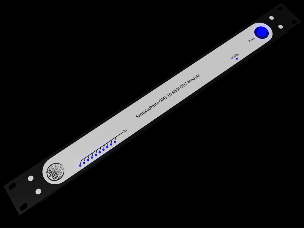
Hello, I recently bought some GM5 boards to make 2 units for my PC, one board with 10 MIDI in and one board with 10 MIDI outs. I bought the little PCB's and I want to create the breakout board. But I had a few little questions about that: The only LED that is on the GM5 PCB is this the USB status LED? Does anyone has a simple schematic for led drivers so I can connect a LED to each midi port? I wanted to know this things before I order the front panels. I just finished the design. Curious about the comments... Thanks! Best regards Hans PS I'm also working on a MIDI router, which will be posted soon, and a MBLC. I hope that I can tell you more about them soon.
-
Hey again, Sorry for the stupid questions I post here :-\ but I'm getting really depressed after sitting a whole night afther the modules and trying to figure out wwhat's going wrong... Is it right that the scanning of the matrix can be visualized on an ossiloscope connected to the DOUT module? I guess I must see some kind of recangtular wave going from 0V to 5V and when I connect my scope to the DOUT pins of the first shift register I measure some kind of "hum". So may be the settings of the sm_example1_v2b aren't correct for my use. And unfortunately I'm not an expert in asm programming. Again sorry for the newbee questions I'm posting here... Thanks for your help! This seems really a great forum!!
-
Hello back stryd_one, Thanks for the schematic! I thought this wouldn't be easy, and it seems I was right... I'll try to be as clear as possible: I connected one DIN module and one DOUT module to the core (j8 and j9). On the DIN I use 2 shift registers (16 rows) and on the DOUT just one (8 cols). The ground of the keyboard is connected to the DIN module (this comes indeed on 25 pins). There are diodes placed between the 8 signals going to the DOUT module according to the C64 schematic on the users projects web site. When I measure voltages, I can measure 5V on one side of every button (so I guess I'm right this far). There is 5V on every pin of the DIN module and on every pin of the DOUT module. I installed the SM_ program (the first version because it mentions rows and columns) but it keeps saying: button pressed on row 1 col 1. Whatever I do it keeps displaying this message. I have really no clue where I went wrong... I'm getting a little hopeless... Thanks
-
Hello everyone, For a long time I've been following the midibox forum and website and I'm building a MBLC and I've build a MIDI router (which I still must program) with the capability of selecting every input and route it to every output port you choose on the screen. When I have the front panel and stuff I will send some pictures. But besides that I'm working on a plan of a MIDI device to control my Nuendo more on the midi part to obtain a better workflow for my works (the MBLC does a very good job for the audio part). It consists of a MIDI compressor/limiter to control my breath controller, some keyswitch patches and a C128 keyboard to give in all my presets and saves (quite a lot). But I'm a little stuck with the C128 keyboard. As I read somewhere on the forum normally you use a C64 keyboard but I have a lot of these old C128 IBM keyboards. So I screwed one open and had a look if I could discover some things about the matrix used. One thing was rather clear, that there are 16 of the keyboard pins going to some resistors and another 8 to some diods. So I guess it's a 16*8 matrix and I'm thinking of remapping and connecting it to a DIN and DOUT module just as an experiment if I can get this working. But the real question here is if anyone of you has an idea about how to connect the matrix? Must I connect the pins from the resistors to the DIN or the pins of diode to the DIN? May be I'm just being stupid to make such an easy approach with the diods and the resistors? This would be such an easy way to connect about 101 buttons to a Midibox Project... I hope somebody out here can help me... Thanks! Hans
-
Hi, Thanks very much for the reply! It seemed there was a little part of the PCB broken on the Vout pin of the LM317, that's why I had this strange behaviour! Now I have my 8V, also using the 240ohm, and my 5k trimpot The faders work very nice... Regards Hans
-
Hello, I'm building a midibox LC, but I'm having serieus trouble with the MF module. The PDF on the yCapps file sais that I need +- 8V over C4 regulated with the 1K trimpot. I connected the MF to different power supplies (one of 16 and one of 12 VAC) and with both of them the max current a got with the 1K trimpot is 5.96VDC, so not the 8V :-s. I bought the MF module at Mike's elektronicsite and there are is nothing printed on the PCB (no offence of course to Mike!) but may be I've put some component wrong or something? I triple checked already with the schematic and the regulator works, but I can't get anymore than 5.96V. But on the next link you can see that normally the LM317 is regulated with a 5K trimpot http://www.national.com/ds/LM/LM117.pdf It's so strange you can do it with 1K, and here it doesn't seem to work... Hope somebody can help me... Best regards Hans PS I already connected one MF, and it worked perfectly with the MF direct control tool it only responded quite slow.
-
hi, thanks to you all! very interesting information, I'll have a look at the alpha version of mr TK and may be so I can support the MidiBox site a little... But now I can continue building my mblc without any doubts... But you think it is possible to connect 2 2x20 LCDs to the module right? Software I guess is no problem, it's more the hardware solutions... I saw a mbLC in the gallery which had this set-up, If someone knows how to give me a hand with those I would really appreciate that! Thanks for all the replies again!! Best regards Hans
-
hello, I recently joined midibox and bought all modules necessary for building a midibox LC. I want to make an emulation of the mackie control, but I have a few questions: -I want to make my controller a little different than the mackie control (2 more encoders on each channel) is it than still possible for software (here cakewalk producer edition) to recognise it as a mackie control? -I want to program my modules in C because I can't program in assembler, so I have to write parts of the software and I got stuck on the sysex part, When I say in cakewalk that I have a mackie control surface connected it starts sending these sysex messages: F0 00 00 66 14 1A 00 F7 and F0 00 00 66 15 1A 00 F7, I already discovered that the 14 and 15 are the control surface and the extension control surface. But now I don't know what my midibox should answer so that cakewalk will recognize it as a mackie control... The fact why I don't use the standard LC assembler version is because I find no way to connect 2 2x20 LCD displays to it, so if someone knows how to do this I would be glad to here this. Hope someone out here can help me... Thanks already! Best regards Hans