Psykhaze
-
Posts
311 -
Joined
-
Last visited
-
Days Won
8
Content Type
Profiles
Forums
Blogs
Gallery
Everything posted by Psykhaze
-
@Sauraen As you work with KiCAD, could you tell me if i should use some librairies from here : http://smisioto.no-ip.org/elettronica/kicad/kicad-en.htm or if you have better source. I've made a compilation of all libs shown on this page. Found nice video tut @ JK
-
Integrating Akai (MPC/MPD)-like pads in Midibox
Psykhaze replied to Psykhaze's topic in Design Concepts
here the Pads controller schematic from MPC2500 SM that could be ok .
-
Integrating Akai (MPC/MPD)-like pads in Midibox
Psykhaze replied to Psykhaze's topic in Design Concepts
ahah , sure :D As i already have a mdp32 and wanted to change the pad set to another color, i told myself that with the future "old" pad set and a sensor i could make some experiments ^^ -
Always here too latigid =) your advice always welcome =) I think i'll start by reproducing the CORE8 / CORE32 / OPL3 modules only from making scematics to the board files. Will be a great exercise. Then will try to chain things on bigger schematics / PCB thanks again, JK
-
As i wrote in another thread, i think i will stick to kiCAD for Schematics / Designs. Really like it. Good soft to share work . Having some tuts right now. My only worry about this soft is the output files for PCB-making companies , as well as .brd files are the standard. But i Think if you use it there is a solution =) Edit : Latigid told me about gerber files so I definately go with KICAD I found some stuff about the wavetable in the MIOS8 code of MBFM.Still studying. See that is not totally useless :D If anybody could tell me about the right quick instruction set for PIC 18F4685 i would really love it. I love assembly . And hates the logic who says "hey, we have much power, so we can code unoptimized way with high level language because we don't care,we have power" Didn't told that any of you is thinking this way, but i often meet programmers who does. May sound weird , i know , but i want to stick to a CORE8 version. Low level code allows to understand things deeply. And I have much spare time right now, Be sure i'll deal with CORE32 too. And i think after studying MIOS8 dealing with MIOS32/CORE32 will be easy as pie. From what you're saying the waveforms for LFO are 1 / 2 / 3 / 5 / 6 ? Same for drums? Thanks, Regards, JK
-
Integrating Akai (MPC/MPD)-like pads in Midibox
Psykhaze replied to Psykhaze's topic in Design Concepts
Look and these ones for backlit versions : Link to Sensor Sheet With LED openings Link to 4x4 Silicon pads backlight-OK The website provides a lot of nice spare components too =) -
Anybody got a good method to convert AI/SVG/DXF files to HPGL? Found tuts about creating a virtual printer to file format using HP plotter driver, but running under Windows 10 i do not find generic driver specified in tuts. Would be useful for Frontpanel Designer. I was thinking about using Illustrator for my PCB design and then convert to DXF to import it in Eagle, that's the why of the thread. Then after few reaserches i think i will not stick to Eagle for Schematics / PCB design. On large size PCB, you need a pro version, and even if i have a cracked one, i do not like the method. My skills with Eagle isn't so high, so i was loonkig for another way of working. Have been told about KiCAD ( http://kicad-pcb.org/ ) And at first sight it's the tool I need to make my designs and to share it. Am I Right? The only issue i worry about is that eagle files is the common standard for PCB companies. And from a fast read , .brd files are accepted in import not in export in KiCAD. Hope i misread .. Can someone tell me about this? Thanks in advance, JK
-
Mmmh after some few tests, doesn't work very well... :/
-
Hi all, As well as the common file format for pcb proto is .brd, I just found a nice trick for those like me who are used to work with DXF / AI etc.. This is a method on how to import DXF paths in Eagle trough HPGL format with inkscape. Found it very useful =) http://badcafe.co.uk/2011/03/20/dxf-hpgl-to-eagle-script-conversion/ Maybe it could help some of you =) Regards, JK
-
Hello All ! Currently working hard on MBFM things, I plan to order a bulk of YAC512 / YMF262 as well as is found a pretty supplier for brand new components. Initial quantities planned 100*YAC512 and 50*YMF262 . More on demand . Will make followings packs i think: - 2*YAC512+1*YMF262 for a single OPL3 - 4*YAC512+2*YMF262 for a double OPL3 Final price for each set not clearly defined yet, just taking the temperature. Feel free to tell if interested, Regards, JK
-
Hi ! Was wondering if anybody has even tried to deal with MPC-alike pads and sensors from mpcstuff ? (Just to know) Link to the pad sensor Link to a generic 4x4 Silicon Pad set Sure some AINSER8 modules may help to midify that thing with a new core32? Asked them a technical datasheet for the sensor part to website sales, hope they will answer positively. Regards, JK
-
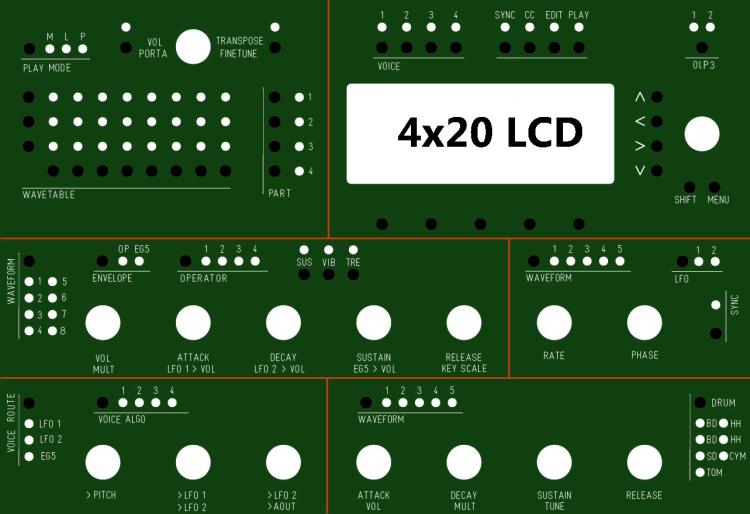
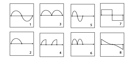
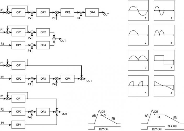
@Hawkeye: Thank you for your answer about shift registers and matrixes . I am planning to buy 2 Cores8 kits , a STM32F4 Board and a second OPL3 Board from SmashTV and some DIN/DOUT IC. Will send him a PM. By the way I was given an access to wiki. Thanks !! I will try to fill it as much as possible when the design will be more "stable". I plan from buying a bunch of 50+/100+ new YMF262/YAC512 too . Found supplier . This way,in a near future, i would be able to provide some of these key components to the build.If some interested tell me. I think you're right about the veroboard prototype of the CS.I will do that. That will allow me to troubleshoot everything before making a "dead PCB" xD Moreover than i have the desired LCD + switches,1N48,encoders and LED here. Just miss some wires, a veroboard and smashTV kits. But buying is planned for june, i should work the others parts while ^^. Once Again , thank you all for your interest . You may find i am like a bounded head , but in the end i find all your advices very useful and try to apply most of design notes provided trough all your comments.really. I do not want to flood the forum in any way, i am just working much on this these days. I ask much questions that i often answer by myself while doing some researches.Sorry. I just think relating about this could be interesting . Why ? First because relating about my design thoughts has helped me to improve really much the things in a short time by being corrected. I would have followed wrong ways in a deep form,loosing much time elseway. I was thinking relating about the way you make a design,the questions you ask yourself, the way you correct it, and make it evolve could be interesting to others though. I'll continue on making some interconnections diagrams for the Project , now that i get many much things better. ( Core interconnection , LEDs and switches matrixes to DIN/DOUT , Link between CORE8s/CORE32 and OPL3s 5V) . Will study MIOS Code of MBFM 1.4 and MB-6582. And MBFM User Manual . And this way i won't post every 5 minutes :D Here are the questions i did not found an answer even after researching (my bad) , if someone could help... *cute dog eyes* - Wich are the waveforms used in LFO and Drums ? (I think i may have forgotten some "waveforms" in the "drum section" of the CS,not sure) You can tell me with numbers based upon the jpeg up there with the 8 waveforms from the manual. - Where can i find exhaustive informations about the 3x 32 steps CC wave sequencer function ? - Is There any big mistake or any big function missing in the CS? I am human and could make mistakes or forget things ^^ - In order to fully understand code source , is this quick reference http://www.cl.cam.ac.uk/research/srg/han/Lambda/webdocs/PIC_Instruction_Reference-1.pdf OK for PIC 18F4685? I am not afraid of ASM,just need some knowledge with common PIC intructions. Big thanks, Regards, JK
-
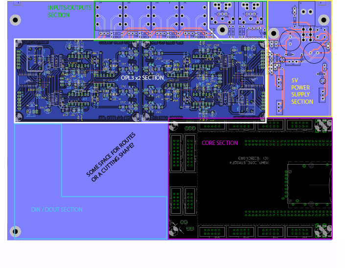
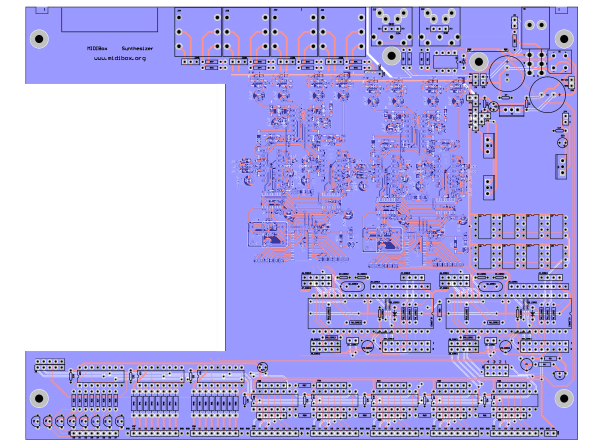
Hi again , in order to explain the 2 layouts versions of base PCB, i've made a good-sized draw based upon MB-6582 to explain the thing. Hope it would help. Regards, JK
-
As far as i've seen from MB-6582 CS<>DIN/DOUT interconnections, I may need : - (8 DOUT registers * 11 DOUT registers) = 88 LEDs matrix - (8 DIN registers * 7 DINregisters)=56 switches Matrix (with 5 unallocated) Please tell me if not correct =) How many shifts register may i need for encoders? i quite did not understood the interconnections to DIN. Waiting for someone to confirm =) Regards, JK
-
@Sauraen I was wondering if you knew some about the 32 steps wavetable sequencer? this is still a dark thing to me in here. Any link welcome =) regards, JK
-
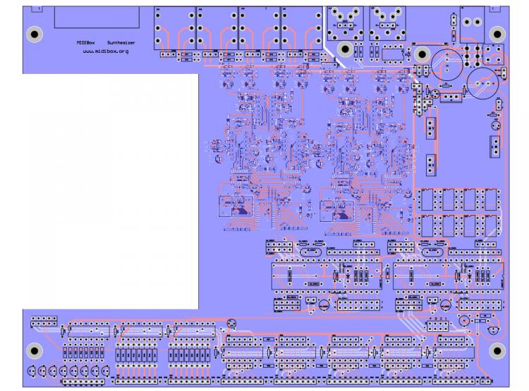
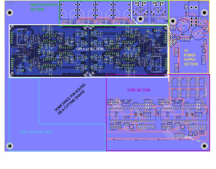
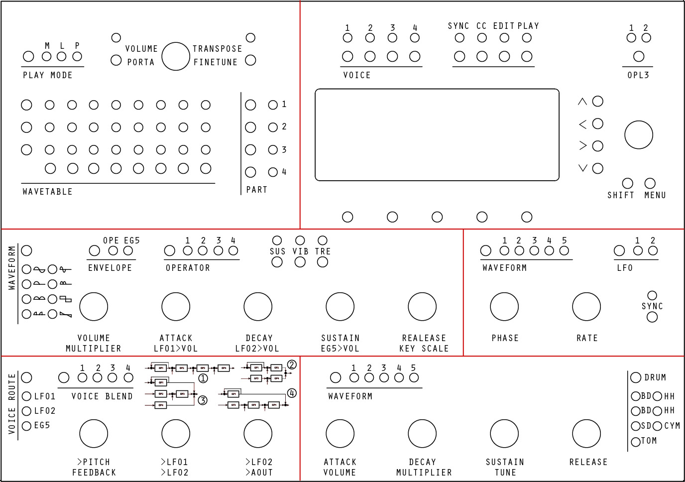
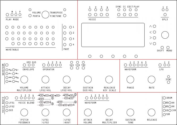
Ok, got the FrontPanel with real sizes on DXF. I incorporated waveforms for the "Operator" section, sounds good . Left the numbers for LFO/Drums waveforms as well i am not sure of the good waveforms to incorporate. Gave a try to incorporate routing diagrams on the routing section . But not sure it will give something good with the scale. And i do find that it overloads the routing section layout. Maybe better to display this on 4x20 LCD? i understand that waveforms would be ugly on the CLCD, but it should fit for routing diagrams? DXF file zipped attached with Jpeg preview. This Control Surface is made of 51 switchs , 88 LEDS (with a (3x8)x4= 32x3 steps Wavetable Sequencer Matrix) ,16 Rotary Encoders and a 4x20LCD,. Still need some piece of advice regarding interconnections with DIN/DOUT: Wich size for the global DIN and DOUT matrixes design?(LEDs,Switches) . Dedicated Shift register for encoders? Before into going forward too quickly on the PCB thing and as well as my knowledge in Eagle is very basic , would anyone recommand me a better software for PCB design in windows ? (Open source and with few tuts would be much better =p ) I have a strong knowledge in the adobe CS suite, maybe i could work with illustrator and then export things in dxf to import it in PCB/CAD design soft? i'll start to think about sections placement (I/Os,Power,OPL3x2, DIN/DOUT and CORE) on a MB-6582 sized Base PCB in order to deal with the 2 versions of this Base PCB. When i'll have made my mind about how working on the PCB thing (>mostly the soft to use) , following to your advices, i'll start up CS PCB. Regards, JK MBFMX2_frontpanel.zip
-
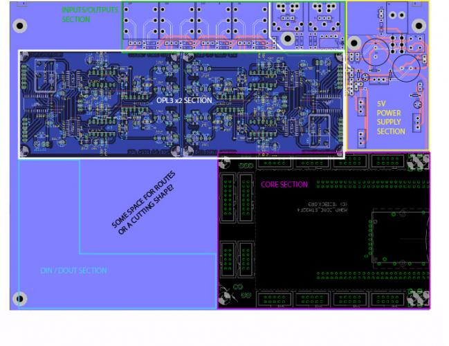
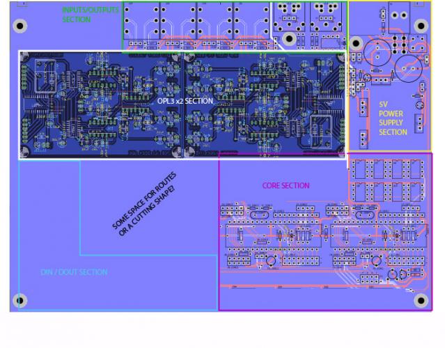
Hello all ! Thank for your advice Sauraen =) glad you answered, will probably need your advice on the synthesis part as well as you know very well the subject =) Sounds like everybody telling me using the new core ^^ . I heard you guys ! and from yesterday i am really taking this seriously in my guidelines . I often work like reverse-engineering , starting with the endpoint (Here the Control Surface) to go forward to the core (synthesis part) . So i'll summarize my roadmap in this project : - First , the Frontpanel : With the UI designed on 'proportions' , in know where to Place Control surface components on the PCB, distance between them etc. as well as i got a MB-6582 CS PCB stuffed near me, i can take dimensions on it. - From the Frontpanel , Count how much DIN and DOUT i would need , and how i would interconnect Control Surface to the Serial Registers .Would maybe need some pieces of advice on this part , as well as many of you experienced the thing much better more than me. - Then , when interconnections from Control Surface to DIN/DOUT would be designed , I will go to CS PCB design. DIN and DOUT will be placed on base PCB. Interconnections between base PCB and CS PCB with sandwich connectors. - After this , i will begin design Base PCB from 4 jacks output / MIDI I/O , and then add the 2x modified 5V OPL3 before . Will keep some place for a 5V power section for CORE and OPL3 modules near the power Switch. - Then , the first challenge is coming . 2 versions of the Base PCB : First One with PICs, like in MB-6582 , and the other one including a STM32F4 core. - The difference between the 2 base PCB will be only the "Core" section : On the first version,based upon existing MB-6582 design, the core will include 2xPIC18F4985 and 8 banksticks. On the second version, the banksticks and the PICs will be removed and include the STM32F4 CORE section / SD card etc.... - Then I will go for Code with some modular design to go into the code before the PCB getting made. This way i could stick to my "PIC challenge" and let other peoples make new crazy things with the new CORE32 with the second version Base PCB for example =) And even if i don't get out of PIC code i would be able to "change my mind" and go for the new core this way. But i want to try the PIC challenge,i've made my mind ^^ . But want to be helpful too, that's why i'll design the second version Base PCB. Sounds OK to you? Regards, JK
-
Ok , I've finished shaping Waveforms / Envelopes / Routing from the manual , i let you see. Attached with the jpeg preview , the corresponding dxf file with 3 layers zipped. I'm going for a sleep, see you tomorrow everybody =) JK FM-Routing-Waveforms-envelopes.zip
-
Hmm , that screen turns me on :D . Sure it should rock !! I am not against using a core32, really! Just for some reasons (that is a choice) i will stick with a 2xPIC design for my MBFM prototype / build . Anyway, in order to be useful to everybody, I will try to make 2 Base PCB versions, one 2xPIC-based (my initial project), and one including the new core32 following Saurean work. This way it should fit to everybody ? The CS would be intended to fit both of these PCB. I do not intend to keep my work closed-source and will share here all my files. In my opinion, the best for the waveforms is to be engraved in the front panel =) I do not intend to go deeper than necessary, but hawkeye told about kinda "hard" mods to make to the source and PIC ASM, so i was gathering as much information as necessary =) Very good news is there is not much assembly to deal with , i've just quick reviewed the source, didn't spent hours on it yet =) If MB-6582 PCBs not publicly available, i'll start upon with eagle files already provided (core8 + ehanced 5V OLP3) The things i like in the MB-6582 are the form factor , the CS design , the scalar design of Base PCB and Power sect / Output placement (MIDI plugs, ON/OFF switch and jacks 6.35) That's why i kept this in the design rules. And programming a bit is kind of game for me =) To explain my goal, i will make a 4 synths liveset (with SEQ, but later and this time with a core32) . I will not Use the PacTec Case In the same aluminium rectangular case with wooden sides,2x MB-6582 (one right to the other,in lenght) In another case of the same size , a TR-9090 and this future MBFM Synth . As well as TR-9090 PCBs form factor is very MB-6582 likely , i kept the idea of the form factor and keeping this old screen and CS design to keep the "harmony" Hope this should explain some of my "weird" choices If i could get a wiki account it could be nice, wait for an admin to confirm it =) Best regards, JK
-
Ok great thanks =) I'll import my photoshop layout in illustrator in order to make a good sized DWG/DXF : this will be my base for components placements in Eagle for CS PCB and source for HPGL engraving in FrontPanel Designer. While in illustrator , I'll import waveforms / routing algos and will shape the paths , this way it could be exported in DWG/DXF or in any graphical form. I have a doubt regarding engraving "place" for routing algos (quite "big" graphics) , maybe some display could be done on the 4x20 LCD? I think the waveforms should be engraved on the frontpanel. I've downloaded the 1.9h MIOS8 and MBFM 1.4 "bios" . Checked the source. Sounds not too hard, even i am still new to this Assembly. Few questions are lasting , want to be sure: - MBFM MIOS 1.4 is intended to run on a PIC18F4685 . So the source has much things already done in it with this PIC. And Wilba used these ones on MB-6582. Is this still the right PIC for this project? (I do not intend to whole re-think everything) - I found a PIC18FXX2 programming ref manual at http://ww1.microchip.com/downloads/en/DeviceDoc/39564c.pdf . Is the instruction set detailed ok for this PIC ? - Not related to MIOS, Is there any way i can access MB-6582 Eagle Files to take it as a start for my PCB design ? - Can I open a wiki page for this project? Thanks in advance for your answers, Best regards, JK
-
Where could i find the waveforms shapes or routing diagrams ?
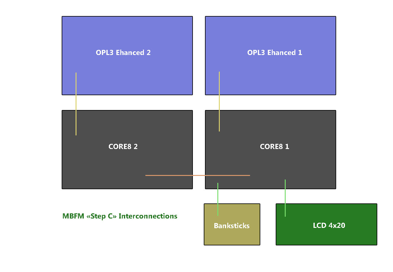
-
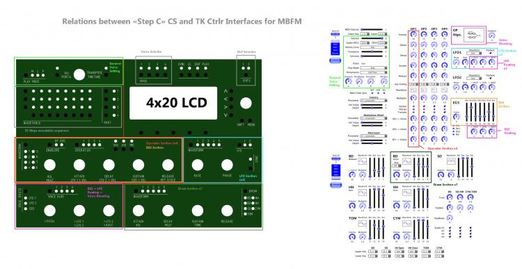
@Latigid on : That's a question of taste, but plastic case are really not my thing. I often recase my audio hardware in wood and steel. More durable to me, and the good things deserve the best :p I plan into casing my 2 MB-6582 and this future MBFM with a TR-9090 in 2 aluminium rectangular (no angled) cases with wood sides . And you're right, playability and longevity are important to me too.That's why i stuck with components used in the MB-6582 Design. Sandwich connector sounds ok for connections between CS and Base PCB , i like them too. I am really into building an MB-6582-alike design, but MBFM adapted. Graphical representation for waveforms/routing could be done in engraving, even if i must admit graphical OLED would be totally geek ^^ That is a choice (maybe not the best) , but i really think i'll go with 2 CORE8 chained , each one driving an OLP3 modified (5V version). I prefer building a robust AIO design than a modular on this one (maybe with some options).Modular design sounds ok to me for experiments and prototyping, not for a "final" build. Much work for the CS PCB and MIOS code expected (especially with this new UI), Maybe less for the Base PCB, as well as Wilba as even considered a lot of things into his design. I already have a good base with the MB-6582 CS PCB design too. In order to make my "Step C" design easier to understand, i've made a parrallel with TK Ctrlr Interfaces for MBFM. I let you see. By the way,may i open a wiki page for this project? Any advices welcome, regards, JK
-
Good evening ! Sure that there would be quite some changes to do to the firmware, but i like challenges , even if i am not a PIC ASM guru :D I am used to deal with x86-64 ASM, so i think i could deal with some PIC assembly. Ok it will take some time, but with maybe some luck i might be helped =) Thank for your interest =) regards, JK
-
Hi Sauraen, I opened a Topic that i advice you to check =) This could be kind of an answer =) best regards, JK
-
Hi everybody, After spending my weekend on reading and brainstorming about the MBFM , I have some ideas i would like to share =) First , i will talk about the Pros and Cons of the MBFM "V2.1" on STM32F4 made by Sauraen and Evolution of Control Surfaces. By studying the way Sauraen worked about FM synthesis and especially in his try to make MBFM evolve, i learnt much. Pros : His Control Surface is visual , advanced and you have quite quick access to parameters when you understood the thing . Driven by the new CORE32 , much fonctionnalities are available. Cons : His Control Surface is Messy and unoptimized at first sight . By making the design on his way "too quickly" and without documenting "well", Community isn't aware of all this amazing work . PCB design is still "modular" Many may not understand, but i think the STM32F4 Core is kinda useless here. CORE8 (with PIC) is well know and understood by the community,and has made its proofs on the "Driving Synthesis OPL3" thing. Do we really need the "overpower" of a STM32F4 ? I think the new CORE32 is more designed to support "heavyweight" applications and UI like RGB BLM, Sequencer etc... Driving 2 OPL3 modules with 2 CORE8 sounds good enough to me. Lightweight is great =) Edit : Due to some good advices , now Really Considering using CORE32 in a second version base PCB , "horsepower" is sometimes useful =) MBSID has evolved with a Control Surface from Step A to C . I think the current MBFM (1.4) Control surface is like a "Step B" . With MB-6582 , Wilba made a full compact All-In-One version of the "Step C" surface of MBSID : Well Designed PCB in 2 parts (Base PCB and Control Surface), designed to fit in a small case, "costless" Components and DIY friendly , Easy Assembly. Everything you need to build the "sweet designed Synth" you ever dreamt of. I want to Build a full featured, nice to look and easy to use MBFM synth. I brainstormed a bit , and i thought that reusing Wilba design could be a start Based upon a screenshot of the frontpanel of the MB-6582 in frontpanel designer soft, i made a Control Surface Design "Step C" alike for the MBFM synth with some Photoshop copy/pastes. Then i opened the MB-6582 Base PCB and incorported good-sized OPL3 modules instead of the SIDs. I let you see. Some improvements could be made on the FrontPanel, like a shape for waveforms instead of numbers. But i think i didn't forgot too much. Waiting fo some advices before going further into that work =) Regards, JK