rasteri
-
Posts
100 -
Joined
-
Last visited
Content Type
Profiles
Forums
Blogs
Gallery
Everything posted by rasteri
-
http://ucapps.de/cmios_fun.html ;)
-
You could probably scale down the encoder wheel down quite a bit as long as the encoder strip is quite high-res.
-
18F4620 is the recommended chip, as it has built-in comparators that make the wheel track better. The bushing squeaked at first, but polishing the stud made it stop. (I just put the stud into a drill and spun it while holding a brasso'd rag to it). I have no idea if a skateboard bearing will work, but as long as there's electrical conductivity between the spinning part and the stationary part it'll be fine. Removing R9 is to compensate for me not having a DIN module, and thus not writing the touch sensor code the traditional MIOS way. Everyone must suffer for my cheapness.
-
I think the only thing you'll need to do differently is remove resistor R9 from the midibox core module, everything else should be fine. If you have any problems, either post on here or PM me and I'll be more than willing to help. I'll draw a new schematic soon, I'm in the middle of making a website for my various projects. I haven't tried torq 1.07 - they might well have fixed the midi bug that was present in previous versions.
-
I used buildroot to make a root filesystem - http://buildroot.uclibc.org/ - awesome little utility. Then it was just a case of building a minimal kernel with usb audio drivers and shit.
-
Here's a quick vid of the latest iteration - it has an SBC inside running linux, and runs a simple scratch program, playing audio on a teeny USB sound card out some headphones. It sounds crappy and has suddenly developed tracking problems for some reason, but it's still pretty fun to play with. dOAZybiCOTk This is the SBC I'm using - http://www.dsl-ltd.co.uk/productspec.aspx?ProdID=ICOP-6116 - it's got a few samples loaded in to a 1GB diskonmodule. Hopefully it should be battery powerable, with a max712-based charging circuit. It's gunna be a while before I have enough time to do any more work on it though... damn job Future plan is to port the code to a dsPIC... it could load samples from an SD card or something.
-
Unfortunately not - the pinouts completely different (for a start there's two less...) I've attached the circuit I'm using, I dunno if it's an optimal solution but it certainly works. EDIT : My schematic was wrong, LyleHaze's is better (see below)
-
I use a 4n25, since that's the only optocoupler my local Maplin had. Never had any problems with it.
-
The infinium does seem to be an awesome product - I'm amazed it's so cheap. Some professional scratch mixers are starting to use it (rodec scratchbox for one). I'm probably gunna stick one in my scratch controller
-
Traktorizer - a Midibox to control Traktor-DJ-Studio -
rasteri replied to MTE's topic in MIDIbox User Projects
I'm not sure... my work has mostly been on hi-res encoders, and the current mechanical jog wheels seem good enough for what the traktorizer is designed for (mixing). Nobody's going to be scratching on a wheel that small anyway. Don't get me wrong - If we increase the wheel size slightly (say to 120mm diameter), add touch sensitivity, raise the resolution and add a better crossfader, then I think we'd have basically the best DJ controller ever. If MTE wants to go down that road then I'm with him 100% - I can help out with code, ideas, anything. -
Awesome dude :) Thanks for having faith :D It's quite often used for shielding guitars, so maybe try a guitar repair store? Electronics stores probably would sell this sorta thing too, what about that Reichelt place you Germans are always going on about? As a last resort, car repair shops often sell tiny overpriced bottles of conductive silver paint for repairing the rear windscreen heater.
-
[solved] Encoder problem and other "scratch box" issues
rasteri replied to Simson91's topic in Testing/Troubleshooting
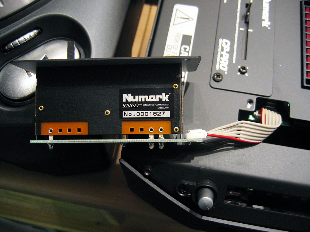
Awesome! love the picture. Great job :) Is that a circular nut on a threaded rod? more pics ;D Nah, crossfaders tend to be linear. Some have two tracks - one log, one linear. Also, the CP-PRO is for numark's range of digital mixers, so I guess they'd want linear. -
[solved] Encoder problem and other "scratch box" issues
rasteri replied to Simson91's topic in Testing/Troubleshooting
I dunno man, maybe you have a defective fader? If you can take it apart, make sure the little prongs are touching the conductive tracks. -
[solved] Encoder problem and other "scratch box" issues
rasteri replied to Simson91's topic in Testing/Troubleshooting
Here's how I think it should be wired up : FADER - 1(wiper) 2(fixed) 3(fixed) | | | | | | PIC pin2 +5v GND Is that what you have? If so, what voltage do you get on the wiper pin? (it should be between 0v and 5v depending on the position of the fader knob). And no, there shouldn't need to be a resistor to ground. The fader IS a resistor to ground. More stuff to try - while moving the fader, measure the resistance between pins 1+2. Then between pins 1+3. Then between pins 2+3. Tell me what range of values you get for each. EDIT : BTW, That's pins 1,2,3 on the fader, not the PIC... -
[solved] Encoder problem and other "scratch box" issues
rasteri replied to Simson91's topic in Testing/Troubleshooting
On your diagram, the leftmost pin is the wiper, and the middle and rightmost pins are the fixed contacts. Wire the wiper pin to pin2 of the pic, and the fixed pins to +5v and ground. -
[solved] Encoder problem and other "scratch box" issues
rasteri replied to Simson91's topic in Testing/Troubleshooting
I've used the dxmpro, the fader seems pretty good. I dunno how easy it'll be to interface though. It doesn't seem to be anything exotic like optical or magnetic, but it comes with a 5-pin connector, so there might be something weird going on. You could probably just desolder the entire bottom PCB though, check the picture. -
[solved] Encoder problem and other "scratch box" issues
rasteri replied to Simson91's topic in Testing/Troubleshooting
yay :D Please post videos. What fader you planning to install? -
[solved] Encoder problem and other "scratch box" issues
rasteri replied to Simson91's topic in Testing/Troubleshooting
Oh and remember to uncomment USE_ADC_ENCODER again :P -
Whoops! found a bug. Thanks to Simon for pointing it out. main.c
-
[solved] Encoder problem and other "scratch box" issues
rasteri replied to Simson91's topic in Testing/Troubleshooting
And we're back to it being my fault again! :P I enclose the latest version of the code. This should work. (ADC_THRESHOLD should have been set to 90, not 0x90...) main.c -
[solved] Encoder problem and other "scratch box" issues
rasteri replied to Simson91's topic in Testing/Troubleshooting
Are you SURE you remembered to uncomment the USE_ADC_ENCODER line in main.c? It shouldn't be using CVRCON or CMCON if you have... I can send you a hex when I get home from work. I'll be about 2 hours. -
[solved] Encoder problem and other "scratch box" issues
rasteri replied to Simson91's topic in Testing/Troubleshooting
Yes, you'll need the latest code. Finally a problem that's not my fault :P (although if you had used the correct code from the start it still wouldn't have worked, because of my earlier mistakes) Get the latest version here : http://www.midibox.org/forum/index.php/topic,11167.msg97570.html#msg97570 You'll need to uncomment the USE_ADC_ENCODER line, since you're using pins 3&4. I.e. change : //#define USE_ADC_ENCODER to #define USE_ADC_ENCODER Even when you use the latest version, it'll still hardly show any voltage on a multimeter, that's normal - it sends a VERY brief voltage spike from RD4 every few milliseconds. If the voltage is still there on RD1 a little while later, then the sensor isn't being touched. That's how a capacitive touch sensor works, apparantly. -
[solved] Encoder problem and other "scratch box" issues
rasteri replied to Simson91's topic in Testing/Troubleshooting
Bugger. I think you just stumbled upon a second error in my schematic. The wire to touch should be on the other side of the resistor. i.e: RD1 (4.9V) ----360K-----RD4 l l wire to touch In my defence, I didn't even know what a capacitive touch sensor was until I started this project (talk about the blind leading the blind) AND I'VE JUST NOTICED ANOTHER PROBLEM. RD1 should NOT be at 4.9v. I just noticed on the core module there's a 10K pullup resistor on RD1, that's probably what's causing it. Remove R9 from the core module for now (assuming you're using a "real" core module and not my hacked up variant). Please accept my apologies for the crappy schematics. I applaud your dedication - I'd probably have given up by now. -
It's illegal for any solder sold in the EU to contain lead. Which is unfortunate as lead-free solder sucks ass.
-
[solved] Encoder problem and other "scratch box" issues
rasteri replied to Simson91's topic in Testing/Troubleshooting
OK, I think I made an error in the schematic. I just checked my circuit and I'm using a 360K resistor, not 47K. I don't know where I got the 47K value from... Also try adjusting the TOUCHSENSOR_DELAY at the top of the code, if that doesn't work. Try a few different values. Let us know how you get on.