highrider
-
Posts
38 -
Joined
-
Last visited
highrider's Achievements
MIDIbox Newbie (1/4)
0
Reputation
-
Ok the Edit mode LED and button work. Work as in mechanically work, the LED lights up the screen doesn't change though. What is it's purpose? I assume once it's depressed :sad: all the changes I make to the patch/ensemble will be stored once I save them, no? I'm slightly confused here because I have saved patches without pressing the edit button. I will change the resistors over the weekend and report back, then I will put the the knobs and the MB-6582 will be finished. It has a pretty white case so photo's coming up :ahappy: Thanks for your help guys!
-
They were supplied with LED's. Stupid mistake.
-
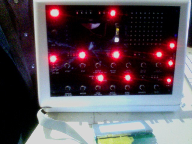
I'm using either 1000Mohm or 47ohm resistors (the bands are too close for me to distinguish where the first band is) with diffused Red LED's 250 mcd. I have attached a picture of the glowing LED's. This is how the CS appears on start up. I've changed all the 165n's and 595's. I'm confident it's not them.

-
Wilba, thanks that picture really helped. The fault was in the IC in U18 after replacing it with a new one everything just worked perfectly including the MOD Matrix and all the LED's that wouldn't light up before. Now I have a question, is this normal? Does the 74HC165 actually make all of that work or have I fixed something without knowing it? Finally, after putting the case together I've encountered two more problems. The EDIT button and LED don't work (I assume because of the LCD causing a short) and some random LED's are on at a very low brightness even when not selected. Has anybody had this problem before? Thanks for your help, Vlad
-
I have found a short between pins D0 and D1 of JD3. These pins are also shorted to ground. Resoldering the wires hasn't solved the problem. Taking the "DEPTH" encoder hasn't helped either. I triple checked the tracks and it looks like there isn't anything to cause a short starting from U17 all the way upto the encoder. Also I have uploaded the LED test up. All the LEDS that didn't work still did not light up apart from the sync led. Does this one work only when there is a master MIDI device connected to the MB6582 and it's sending tempo info? Thanks
-
Thanks for the advice! Unfortunately this didn't solve my problem. I opened the encoder (from Voti) made sure the wipers are straight and the right height. I even put the metal ring back to where it was (to make it detent again). After putting it back together it still doesn't change value. Than I changed the depth value with the menu encoder, all the way to -127. Interestingly after trying to modify it with the encoder in question the value would rapidly go up all the way to 127 regardless of which direction I would turn the encoder. Also, If I keep turning the encoder anticlockwise the value changes only in very small increments (1-2) but immediately returns to 127. It's as if it's been pulled there. I am confident it's not the wipers unless this is what you experienced with your encoders? V! Update : As it turnes out with an encoder stuffed (i tried two different ones) the result is the same. Depth values go up to 127 and barely nudge from that value. On certain occasions the CS freezes on the envelope screen i.e. everything works but I can't navigate back to any other editing screen. Note : this doesn't happen when there is no encoder stuffed. I'm shure there is a short or damaged track/pad somewhere thats causing this behaviour in the envelope section but following the tracks from where the encoder used to be I see nothing wrong with the PCB. Could it be the 165N's?
-
I managed to fix two sections . There was a damaged track going from the diode to the LED in the CONTROL and in the SID ENGINE sections. Now the LEDS light up like they should!
-
Thank you for the advice Filch. I have removed the LCD from the CS. Apparently there were no shorts because all of the problems persist. Otherwise it works as it has before. V!
-
Once again I ask for your help. Hopefully this will be my last troubleshooting session. I have successfully connected the CS and LCD. The MB6582 is functional through all 4 SID engines but there are a few quirks that don't let me seal this beast of synth inside the box just yet. I'll Start with the LEDS 1) the whole vertical row 3 of the mod matrix is not working.- fixed 2)Waveform LEDs don work (although waveforms change when I press the respective button)- fixed 3)Control ENV MISC KNOB LEDS don't work (again this section is fully operational) -fixed 4) LR SID section LEDS don't work while sids can be selected.- fixed 5) Sync MODE LED doesn't work ( just the LED)-was not a problem 6) SID ENGINE 2 LED doesn't work as well as the button i.e. it can't be selected even though I can play it through MIDI CH2 - Fixed Buttons 1) The aforementioned SID Engine 2 button. I can change the engine via the menu encoder and buttons. - fixed 1)2) The horizontal row of the mod matrix. I presume that it's not working because any two buttons of this row pressed at the same time don't change the MODE.- fixed Encoder 1)- Just the Depth Delay Encoder dowen't work at all.- fixed One more thing that may help : When I select LFO waveforms the LEDs in the LFO 123456 section light up but very dimly (one at a time with every push of the button in the wave selection). I have noticed that through out the CS this happens quite often . The light is so DIM it can barely be distinguished from being fully of. I have went through all the connections between the CS and Base and have found no shorts and no breakage in connection. After tracing the tracks on the CS diagram I couldn't establish any pattern to determine the source of the described faults. To the best of my knowledge the PIC's and SID's are in full working order. Patches change/notes play through all SID engines. So far I think that I might have just damaged the non working LEDs apart from row 3 in the MOD matrix. I will do the LED test next and post the results. Please reply if you have experienced similar problems or have any advice to share on how to carryout the troubleshooting. Many thanks, Vlad
-
Sorry I misunderstood you. Good luck in finding those knobs!
-
You need these : http://cgi.ebay.co.uk/9x-500K-Potentiometer-Pots-Taper-Dual-Pinned-Step-B500_W0QQitemZ300365920167QQcmdZViewItemQQptZLH_DefaultDomain_0?hash=item45ef3437a7#ht_1205wt_941 I have just ordered the exact same pots so if you need any I can send/give you the remaining 5 free of charge. Have you built the control surface yet?
-
MB-6582 Need advice on troubleshooting audio buffer
highrider replied to highrider's topic in Testing/Troubleshooting
I agree that the logical step is to change the ID of each problematic pic. Unfortunately I don't understand how to compile the hex file with provided code in the readme file's. I tried to read the wiki but I failed to make sense of it...so I'll have to pass on this one. I need know if I can exclude bad soldering as a possible cause. If my master PIC 00 is working in each socket without a problem this means that all the MIDI comms are fine throughout the 4 cores, right? If understand correctly it's not different for the slave PICS i.e. if one PIC is receiving MIDI then the others should as well. I have a fully loaded PCB (all IC's in their sockets) no resistors for LED's though. No LCD just the base. I have the SID rc35 app uploaded to pics 00 01 and 03. 02 has the test tone atm. Earlier when I had all pics with mb sid rc35 the behaviour of pics was the same (note on hold or mute after 2-3 seconds). I'm assuming that the pics stop working because they no longer respond to midi notes/cc's until I reboot. With an arp sequence going from my midi controller (akai mpk 49) the sound still stops after 2-3 seconds on pics 01 02 03. I have checked the voltages on all the IC's and I'm getting 4.88V (sids 8.87). I can still hear what I play through channel 1 output after the other stop. Pic 02 outputs the test tone even with 01 and 03 not working. Btw Can I re-upload MIOS 1.9G to each pic to format the bank sticks and to exclude the possibility of wrong software uploads causing the problem? I just remembered that I have uploaded the vintage bank 4 times (with MB sid editor) to PIC 01 (by changing the bridge on J11). I haven't understood the manual correctly and thought that I have to upload the bank through each core to have the patches working on each core. I did this because previously the vintage bank was only available through pic 00 while other cores only had the lead sound. Perhaps by uploading the bank 4 times to PIC 01 I have caused this problem. Actually the patch I hear after power on is not a lead sound at all, it's more of sequenced riff... Can you confirm that it's alright re upload MIOS 1.9G so that I can start over? Thanks ! -
HI guys, just a quick question. I don't read datasheets well but I'm thinking that this is the right encoder If I'm wrong could you please recommend an online store in the EU where I can order the right encoders? The links in the wiki are either german shops (I can't read German) and I can't find any reasonably priced encoders on UK links Cheers!
-
MB-6582 Need advice on troubleshooting audio buffer
highrider replied to highrider's topic in Testing/Troubleshooting
Wilba, thanks for replying so soon! You helped me so much! It was a broken resistor leg that was the problem. I couldn't see it earlier because the resistor was in an upright position and the second leg was concealed from view. So as I was trying to perform a continuity test I accidentally pressed on it and it turned out wobbly. I put a new one in and moments later the SID sang a 1Khz tone. Now I have every output fully functional. My final task is to determine whether I have broken PIC's 01 02 03. They all work fine with the test tone app. All have successfully uploaded MB sid app V35. The core modules work fine with my only fully operational 00 PIC , but the 01 02 03's play for a couple of seconds and then either hold the note or go completely mute. Voltage checks have passed. All I could find by searching the forum is that people with similar problems had to buy new PICS , but I couldn't find a single confirmation that this resolved their issue usually the threads just stop after that. It seems that I'm missing something and I don't want to just order more pics without being at least 90% sure that the PICS are actually broken. One more thing. I haven't put the Pics in slave mode as I don't have the menu button yet. I have just uploaded MB sid to each pic while moving the jumper on J11 with each PIC in it's respective core. Should I try to upload the MB SID app from core 1 only? (R80 in place, diodes positioned correctly) Am I providing the right information? Cheers! Vlad -
This is off topic. I have been troubleshooting for ages and I'm almost sure that 3 of my PIC's are damaged. If they are damaged than it's more likely that they have been damaged by me (no guessing) and the last thing I would do is "demand" Tim to reimburse me for it. But I'm sure you're not aiming at me anyway.