

Janis1279
-
Posts
287 -
Joined
-
Last visited
-
Days Won
1
Content Type
Profiles
Forums
Blogs
Gallery
Posts posted by Janis1279
-
-
-
Hi,
MIDIbox FM Demo Samples part included some non working links.
one of it (Schematic from Rick Jansen) is possible to restore with the updated link https://janswaal.home.xs4all.nl/Emusic/Moog/, I think.
Regards, Janis
-
Hi,
- I do not know how you are planning to organize cooling inside yours MB-6582 case. When you are using a single 12V power supply you will get a lot of heat from a +5V linear stabilizer ic inside the SID synth case.
- Some about feedback pots from one of Hawkeye messages:
"1. 100kohm work fine, 500kohm will also work... the value just specifies the max feedback "dampening" which is at maximum for 100kohms already.
2. you need four "stereo" feedback potentiometers for four stereo pairs of SIDs, no matter what type of sids."
or otherwise you don't forget to grounded an analog inputs.
Regards,
Janis
-
Hi,
as you see it's some info from Wibas mb6582 building files.
At first you can print it for the better understanding for the matrix structure, I think.
http://wiki.midibox.org/lib/exe/fetch.php?media=mb-6582:mb-6582_cs_dout_wiring.pdf
http://wiki.midibox.org/lib/exe/fetch.php?media=mb-6582:mb-6582_cs_din_wiring.pdf
When I built my MB sid custom CS, it helps a lot.
Regards,
Janis
-
 1
1
-
-
May be you can check all signal diodes 1N4148 are right polarity oriented .
-
Hi,
Here is a default encoder assignments for MB6582:
http://www.midibox.org/dokuwiki/doku.php?id=default_encoder_assignments
On the shift registers appropriate pins you can check pulses, when you slowly turn encoders knob.
ps. some encoders have a different pinout, if yours are from another manufacturer.
"Patience is a virtue"
Regards,
Janis
-
Hi,
The resistor networks are possible simply measure with the multimeter. If it not proper pinout , you are able to solder ones very fast from the separate resistors.
Regards,
Janis
-
1
-
-
Hi,
May be you need to recheck the soldering again, not for bridges only. The Led's and buttons are controlled by shift registers. To check all the ic's for right direction installed, for no broken ic pins and for it are in the sockets in right places.
Regards,
Janis
-
1
-
-
Hi,
The simplest way is to check interesting connection points on the pcbs with the multimeter with a beeper. Thenafter with the power on to check all voltages on the supply rails on the pcbs.
Regards,
Janis
-
Hi,
May be the 9vac wallwart is too weak. The Sids are eating a lot . Which Sids and how many are installed ?
Regards,
Janis
-
hi,
The DINX4 and DOUTX4 modules are always connected to the Core module ports. On the complete MB6852 base board these chips are located near long connectors row at the edge of board.
Regards Janis
-
Hi,
In the wiki pages you can read some more control surface troubleshooting info http://wiki.midibox.org/doku.php?id=control_surface_troubleshooting&s[]=mb6582
The standard control surface has a PLAY button and it will be useful in farthest tests, with uploaded patches. For that the JD5 and JD8 slots are with the i-cs, of course.
Good luck!
Janis
-
Hi,
Thorsten, many Thanks!
Let's think forth.
Best Regards, Janis
-
Hi,
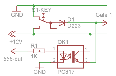
With the Pic based core tested midi in with some keyboard keys:
Keyboard keys originaly are grounded , tried to make logical OR, diode is signal diode, as 1N4148. An idea using the optocouplers is from Doepfer the Solina midification pdf example. With the 60 keys will be 60 gates signals, it's paraphonic musical instrument.
-
Hi,
I have a soviet pseudo-polyphonic almost analog strings-musical instrument Opus.It sounds great.
Interested to midify it, but not sure which way to go?
For controlling the filter or some of the filters I need to build MBCV,I think. But this way isn't useful to midify the keyboard's 5 octave keys .That I understand from some readings.May I need to merge 2 pieces PIC18...based cores: the MBCV and the Midio 128 for that?Whereas with the newest LPC based core I'm not sure in my possibilities to make a right software part for that.
Can any knowledgeable to give some more advice?
Regards,
Janis
-
Hi Kike,
Are the Sid chips audio input pins 26 tied to ground (with the small jumpers)?
Regards,
Janis
-
Hi Kike,
For the basic Sid part schematic understanding it's a good habit to use a MBHP_SID_V3 schematic from the Sid Module section. It can help to understand the audio path part and the control pin part of the Sid chip. The schematic is the same, I think.
There are a lot of soldered wires - jumpers on the Twinsid main board. If you are used the same layout board you need to check a presence of every jumper - wire , under the ic's, too. Visually check all solder places on the pcb, not the shorts between the traces,too. To check a non solderable jumpers too.
Supply voltages tests idea are similar to the sammichSID_build_guide_v1_0.zip from page 18, but there are another components layout of course.
To check: right supply voltages for your sids , the right nominal similar capacitors for the sids oscillators on the sid pins1/2 and 3/4.
Regards,
Janis
-
Wicked! Thanks lmp! I have the large base board that has all cores on it. I have been reading through documentation but havnt seen or missed the part about usin jumpers to choose what the rail voltage is for each individule sid core. That's great news!!!! I'll go and try to find instruction in the build doc. I had seen information about what jumpers to use I the section discussing power supply options (a or b etc...) but hadn't seen any mention of using different voltages to individule cores. Cheers, mr. baggins
Hi,
Power supply option B is a right option for two different type of the sids.
regards,
Janis
-
Hello,
I will get a brown C64 today, which will complete my set of 4xcores, 4x6581 and 4x8580.
I will use the optimized PSU set-up, and some things are not yet clear for me:
- the 7805 are dropped because the PSU provides stable 5V
- there is a 7809 to stabilize the 9VAC output, and combined with the 5VAC output, it provides 5VDC and 14VDC
- the "Optimized PSU" document don't mention the MBHP_SID 78xx : do I need to put one 78xx by MBHP_SID, or can I use one 7809 for the 8580, then link the power to the three others, and the same for the 7812, or is it better to have all MBHP_SID their own 78xx to avoid ground loops?
Kind regards,
Xavier.
Hi,
For the 8580 you need to use one 7809 and for the 6581 you need to use one 7812. The inputs of both voltage regulators are connected together to +14VDC rail. It is possible to use the common heat sink, as ground pins of the regulators are connected together, too.
Regards,
Janis
-
Hi,
Will be fine 12VDC 1A.
Wilba said: If using 8580, a regulated 12V power supply is preferred but not essential.
Regards,
Janis
-
Thanks for your reply. When i have nothing connected, the outputs of d0 .. d3 are high. I use mios v1-9g with bootloader v1.2b. I have built another core with only nessesary connections and it stays the same.
Best regards, Pim.
Hi,
Are you testing another FM soft with your Core module, too, not sammichFM soft only ?
May be I am not right.
Long time ago I had similar no sound event.
Regards,
Janis
-
Hi,
There are a lot of inductors ( coils ) you can find on an old computer motherbord.
Regards,
Janis
-
Hi,
Another simple noise gate schematic - LPM-23 1 channel I been made on a breadboard and tested with the MB6582 with 4x 6581, too.
http://hammer.ampage.org/files/LPM-23-NoiseGate.PDF
More detailed info about components you can find in Mark Hammer posts in this forum http://www.diystompboxes.com/smfforum/index.php?topic=81918.0
- In the schematic an OP amp pins 3 and 12 are need to be connected to a +5V chain. It's according to a pcb layout.
Regards, Janis
-
Hi,
Possibly too small output current.
In the project startup phase browsing forums is a better way to collect info what you need.
Regards,
Janis

LCD problem, help?
in MIDIbox SID
Posted
Hi,
Are you compared the both LCD screens pinouts in the corresponding data sheets? It's possibly are different.
Regards,
Janis