

Janis1279
-
Posts
287 -
Joined
-
Last visited
-
Days Won
1
Content Type
Profiles
Forums
Blogs
Gallery
Posts posted by Janis1279
-
-
if i remember correctly thats what the datasheet for the lcd said the backlight needed. I don't have it anymore and am trying to find it online, but there isn't a lot written on the lcd. i hope i can use this because i have 2 more just like it.
If you returned to the scheme MBHP_CORE_V3 to the connector J15, will see pins in the two columns. Right sizes first 2 upside pins are marked : B+ , B-. These pins supply voltage "+" and "-" polarity ( or need suplly voltage ) to the yours LCD backlight pins.
I have simpler this part of the scheme with only one 10E resistor , but its not so important.
Regards, Janis
-
I decided to start working on this project again.
They are connected in parallel.
The lcd backlight draws more than 1 amp of current when its on. I think I need a current limiting resistor in series with the backlight right? When I disconnect the lcd backlight the 7812 doesn't get hot.
Why 12volts to the LCD module ?
If you see scheme of MBHP Core , you see only +5V and gnd connections, right?
Your comments about more than 1 amp of the LCD backlight current sounds : all is not so good.
You need against checked every connection to the LCD module .
Regards, Janis
-
Hello all,
I'd like to know if IIc Midi modules are supported by MB64 or MB64e application?
It would be for adding some Midi Out to my project.
I have a LTC module, but i need one more Midi Out.
Is it possible to use LTC out, IIC midi module(s) Out and Core midi Out at the same time?
I could be wrong.
You can use LTC out, 2nd Midi out from MBHP_LTC_V1a sch. and also add in a similar way 3rd Midi out.
I think you may connect additional 74HC00 i-c to J1 MI , MO pins as in scheme are connected IC3 , R7, R8, J5 , socket components for getting needed out.
Hope, you will find solution !
Regards, Janis
-
hey
for members of another forum only, many as one year old info :
http://launch.groups.yahoo.com/group/midiguitar/message/27224?l=1
but for free find only Microswitch Charts for MG-500/510 :
http://jpsongs.com/troubadortech/casmgtr.htm
Regards, Janis
-
My question is really simple.
Can I use the PIC BURNER module to program a pic16f84a?
As I understand from Pic Burner manual and :
http://www.sprut.de/electronic/soft/pbrenner.htm
I say : YES
Regards, Janis
-
Those crimp sockets I presume is something made in copper, right? It can be made in other type of material? Because a got some pieces of aluminum in various thicknesses to try to make my homemade frontpanels, then maybe I can use some of these pieces to try to make my homemade crimp sockets.
KB
crimp sockets made in copper and soldering well.
I made in some steps :
- at first cuting and soldering ribbon cable leads,but very short lenght! When heating , insulation decreases fast,
- puting on working place all needed crimp sockets together in one peace, fixing it,
- then acurately soldering one by one,
- after, working with a pair of flat pliers.
Regards, Janis
-
Don't go crazy trying to make single row header connectors with a pair of pliers.
Similar size crimp sockets I made with a soldering iron and with a pair of flat (~5mm width), long pliers. It's simply, only sometimes, need more patience. Result is fine , too.
Good luck, Janis
-
-
I could be wrong. I don't use com port connection.
If you have right Yamaha driver. In Mios Studio/MIDI/MIDI Devices push "Rescan devices" and "you see" your midi core. After : Options/Midi device rooting and forward .
Regards, Janis
-
? ??? ?????? ????? ???, ?? ????? ???? ????? ????????? Mios Studio ??? ??????? ??????????? ?????. ????????? USB - MIDI ???????????????? Edirol UM-2ex ?? ???????.
?????? ??????????? ????? ??? ?????? "??????????? ???????" ?????????????? ????, ???????? ? ????? ????? ???? ??? ??? ?????. ????? ? ?? ?????? ???????????.
????????? , ??? ?? ?? ???? ? ??????? ?? ?????? ????.
?? ?????? ?????? ?????, ?? ??????? ??????? ? ??? ???????? !
? ?????????, ????
-
...
Noone sees the line between the fuse and the ground ......?
This line contains a led/diode and a resistor...
This is about that piece of wire i have doubt
Read ( 2 ) under drawing .
-
ok to close the circuit, of course.
BUT, on this schematics, there is a big short circuit, for my opinion ... but indeed, I have to understand something that seem to be hard to explain.
the circuit will be close by putting the 5V to the 5V input on the core, and the gnd of the core to the gnd of the psu. right?
If you have +5V supply, you don't need any voltage stabilizer circuit. Because shorted circuit In with Out.
In these stabilizers voltage drops~2,5volts, and they working with higher voltage ~+7,5volts to~+35volts.
Regards, Janis
-
hi!
i'm searching for a simple panel mount tactile switch. when i search the mouser site they bring just the normal small pcb mounted ones. if i search for pushbuttons they show panel mounted ones but just very expensive / vandal proof / backlight / high amperage etc.
what i need is something like a panel mount version of the switches Mike offers or sth similar.
any ideas / experience?
or perhaps i simply use the wrong term when searching ??
Hi!
For panel mounting you need search push button switches.
Only as an example :
http://yqyiwei.en.alibaba.com/search/product?IndexArea=product_en&SearchText=Push Button Switch
Regards, Janis
-
Are your 8 encoders with right pinout connected to DINx4 SR input pins i0-i7 as in example file for 16 encoders ? Is external cable right wired : Vs to Vs, Vd to Vd, S1 to S1, SC to SC, RC to RC to the correct Core port (reading commentary to schematic, too) ?
-
i have 8 encoders hooked up, though i don't get any midi signals through midiox or mios studio, i've also tried both J9 and J6.
I could be wrong.
When you tried both J9 and J6 with J1 DINx4, are you seen some differences in pinouts ( mirror ) ?
From left to right side on core
for J6 : RC SC S1 Vd Vs
for J9 : Vs Vd S1 SC RC
Regards, Janis
-
I change my PSU and trouble is the same :( , and faders are wired correctly ... when I change software from MB64E to MB64 everything is ok. Maybe my config file is wrong ??
I could be wrong, but in setup file for MB64E for faders you only need define quantity = 16 and enabled mux = 1 :
#define DEFAULT_NUMBER_AIN 16
#define DEFAULT_ENABLE_AIN_MUX 1
Regards, Janis
-
it seems i had the pinout wrong :P.
i did a test circuit with an LED and resistor to see which pin was the ground, turns out what i thought was the first data point was actually the ground.
just shows to never assume, though now that i have it all wired up as the correct pin out i still get no midi signals while tweaking the user inputs(encoders).
i've tried to crudely make my own hex file to tell it where my encoders are(first DIN J3;J4;J5 using only half the digital ins for J5).
i have 8 encoders hooked up, though i don't get any midi signals through midiox or mios studio, i've also tried both J9 and J6.
If you have 8 encoders hooked up, you need 2 SR for example: connect to all pins of J3,J4,J5,J6.
I made some little changes in source file code . DIN module you need to try to J9 of core.
-
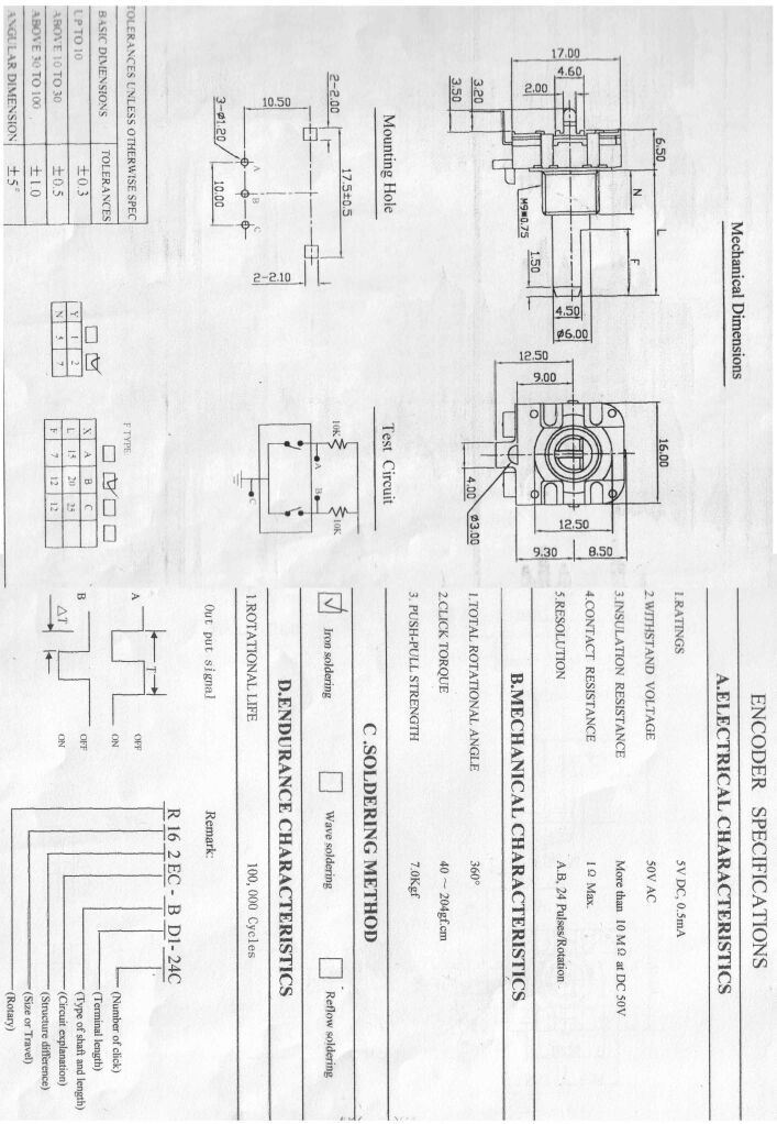
1. All encoders are not the same pinout. From wiki:
http://www.avishowtech.com/mbhp/images/encspecs17.gif
http://www.voti.nl/docs/rotary-encoder.jpg
2. As I understand :
with old Pic16f877 core DIN module(s) is connected to J6 , but with pic18f...core is connected to J9 .
Regards, Janis
-
1. Simple, helpful midi signal tester :
http://www.epanorama.net/circuits/miditest.html
2. One of my midi cables I made from old PC keyboard cable with original DIN plug on one end.
-
Is your external wirings is correct, too ?
-
Some info for similar, maybe, product : CM24064-1 from the same manufacturer.
-
I am happy, thanks for answers, Thorsten !
1.
When made similar changes in MIDIbox64e setup_...asm for conecting datawheel and second encoder as for low cost solution, result was given correct and both encoders works fine without any flashing leds.Could you please attach your modified .asm file to this article? This should give me a complete overview.
Attaching both, but problems to this moment with MIDIbox64 .asm file
2.
If I want used only 1*DOUT Module with SR#1-4, where can find address table for and custom define the DOUT pins for the Rx and TxIt's in the Wiki:
http://www.midibox.org/dokuwiki/doku.php?id=home:mbhp:module:din_dout_pin_list
Thank you for this link, too.
But for the first shift register, which interesting much more, in the pin hex number colon found only zero values. When read hex values for another shift registers, understand and made changes in Midibox64 (e) asm files.
And Rx and Tx leds lights.
Regards.
-
Hi.
Thanks Thorsten for your great site ! ! !
How there are recomended ,read, read , but any way I have some questions.
I have self-maded Pic based core, DIN Module, DOUT Module pcboards, some detented encoders from Alps , buttons, LCD 2*16 , 8 pots connected on J5 without mux .
1. Connecting datawheel encoder as recomended to SR#1 pins 4 and 5, made some changes in setup_...asm file (for datawheel put "1" instead of "-1"), compiling, uploading . See noncorrect Datawheel function, output module leds switching on off, too, when turn knob . It's looks like don't correct defined encoder. In mios_tables.inc changing detent to detent2 without any success,too.
When made similar changes in MIDIbox64e setup_...asm for conecting datawheel and second encoder as for low cost solution, result was given correct and both encoders works fine without any flashing leds.
2. Have another question from the source file :
; For MIDI activity monitor: define the DOUT pins for the Rx and Tx LED
#define DEFAULT_MIDI_MONITOR_ENABLED 1 ; if 1, the Tx/Rx LEDs are enabled
#define DEFAULT_MIDI_RX_LED 0x40 ; DOUT SR#9, pin D0
#define DEFAULT_MIDI_TX_LED 0x41 ; DOUT SR#9, pin D1
If I want used only 1*DOUT Module with SR#1-4, where can find address table for and custom define the DOUT pins for the Rx and Tx LED?
Thanks.
powering pots
in Design Concepts
Posted
Yes, it's right. Only , when mirrored text, pots connections looks like reversed.
Redrawing some lines for better understanding.
Regards, Janis