noofny
-
Posts
72 -
Joined
-
Last visited
Content Type
Profiles
Forums
Blogs
Gallery
Everything posted by noofny
-
Thanks stryd_one...will give that a go - makes sense in retrospect. Sorry about the cross post didn't realize. Thanks again for the quick responses. :-)
-
Should I be supplying the ULN's +5v directly from the +5v out on the PSU instead of through the CORE -> DOUT power chain ?
-
yeah thats what i thought too....but I dont understand enough about it. Could it just be a logistical thing whereby chaining the 2 matrix boards causes the total circuit to be physically too long/large for MIOS to scan? The longest cable from DOUT to LED group might be almost 2ft..?
-
Nah...it's defiantly a hardware problem. Whenever more than a constant number of SR outs are driving the annodes the core craps itself. It doesnt matter which SR pins, just over a certain amount of pins activated on both DOUT's will lock it up....must be a current/supply issue. I was reading Ralf's great doco here http://www.suckow.de/ralf/ledmatrix4x20/ on his matrix circuit and he mentions he used 74HCT595N instead of the standard 74HC595 because they support a greater current. I've searched Farnell and others for 74HCT595N but nobody sells them?? Can anyone shed their knowledge/opinion?
-
yeh hold off guys it looks to be a software glitch....something in my C routines that is weirding it out. I'm trolling through it now. I created another sequence which cycles through the columns first, then the rows...this doesn't lock up at all. The orig sequence that cycles through rows locks up on the first row...anyways. Once i get clearer i'll post more info and code...sorry jumped the gun a little. :-)
-
I wrote a simple routing that cycles through each row/column and turns on each LED. 1) I connect both matrix boards to the core and trigger the sequence....the first row of LED's for each matrix lights up and MIOS locks up. 2) Power cycle. 3) I only connect the RED annodes on the 2nd matrix board and trigger the sequence. 4) Works 100%. 5) I connect the RED & BLUE annodes on the 2nd matrix....MIOS locks up. ...hmmm it seems if I connect any more than 1 set of annodes on the 2nd matrix it locks up. 6) I connect only the RED annodes on the 2nd matrix. 7) I fire the sequence and half way through I also connect the BLUE annodes....works 100%. 8) Now with the 2 sets of annodes connected (RED & BLUE) I fire the sequence...MIOS locks up. This is weird. There's no shorts or anything...the boards work 100% on their own...seems like a quirky SR behavior?
-
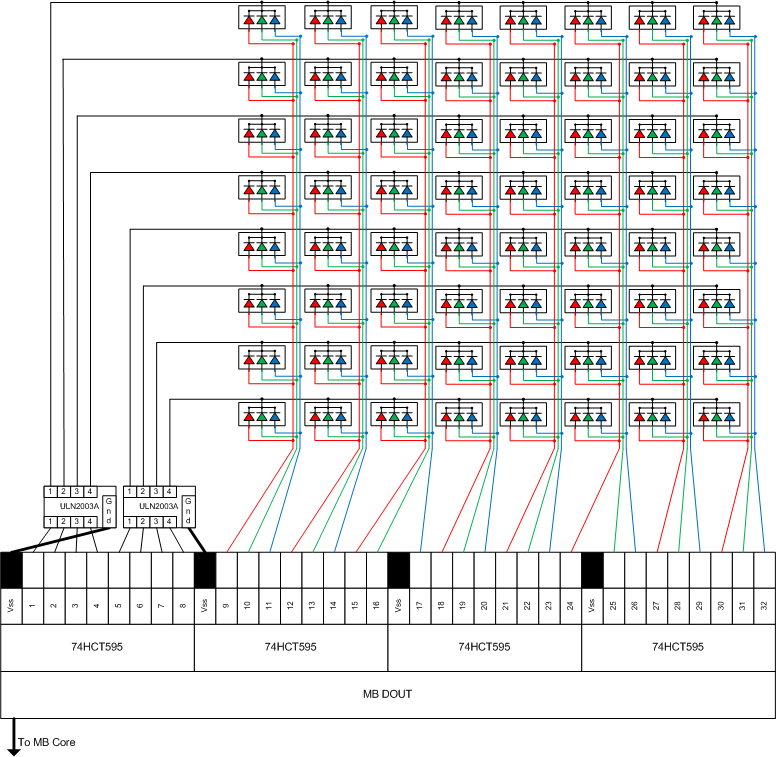
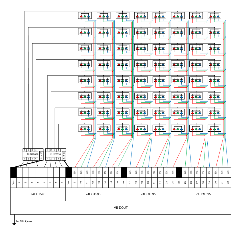
I've made up 2 8x8 RGB LED matrix boards using DOUTs (see attached circuit). When I connect a single matrix board to the core everything works 100% (for both of them). However when I chain both matrix boards together to the core, MIOS locks up on power up (and all LED's light up full). Both matrix boards work 100% on their own, just when I try chaining them together the cores lockup. Seems like the circuit is getting overloaded or something? My PSU is supplying more than enough current (over 5 amps). I'm wondering if the core circuitry can handle both matrix boards connected? Is the problem with the SR's...do I need different SR's...the ones I'm using are just the standard 74HC595 ?? I'm just lost at where to start trouble shooting - would really appreciate if anyone can shed some light. :(
-
Cool...got the clip matrix (finally) finished! http://noofny.blogspot.com/2009/02/bling-matrix.html I tells ya, this is the hard part for sure! All worth it though 8)
-
Yeah I didn't think to look there because I imagined I would have to call an external library (not a C programmer you can see). In retrospect thinking a bit about how the app layer sits with the os (mios) I guess it makes sense to have calls like this available this way. Will look here in future but thanks for the responses.
-
Perect. Thanks Phil. Damn this forum rocks don't it! 8)
-
I'm doing a simple routine that shows off the RGB matrix when you switch it on, like a fancy demo to make all the lights go pretty blinky colors. I need a way to put a brief pause between my loops. Simple thing, but how would I do this in my midibox app....what library would i reference or is there a core function already there i could call for a sleep/wait/pause. Nothing seems to be around on the forum about it?
-
took some vids...still not done but getting close... http://noofny.blogspot.com/2009/02/update.html
-
Hey cheers for the comments! I've been working on the software and RGB LED matrix the last few weeks so haven't updated in a while - but once the LED's arrive from China in a week or 2 i'll have the final phase done and will post updates and move the doco into our wiki.
-
Solved it - gotta love in-play school! I thought you had to feed -v into the darlingon in's, but you feed in +v and it outputs -v. Still don't really understand how that happens but there's a lot of this going over my head - just glad it's sorted though. So when setting the DOUT pins 1-8 I do MIOS_DOUT_PinSet1(x) where x is 1-8 and I do this in the Init() function. Then you call MIOS_DOUT_PinSet on/off for the r/g/b pins. Awesome...get it now! :)
-
I've built my DOUT with the added ULN2003A's as per the attached circuit pic. This is to eventually achieve an 8x8 rgb led matrix. Everything works fine as far as the DOUT is working 100%. What I'm stumped with is that there is nothing coming from the output pins of the darlingtons?? For example I place a multimeter across +5v input pin of the DOUT and pin 1 (input) of the darlington and it measures 5v - which is right. Now I measure across the matching output pin and the same +5 input of dout and it measures around -2v. The chips are working and bought new and both are doing the same thing across all outputs. I've been reading and checking against circuits all over the net and I've wired them the same as everyone else (except haven't wired anything to pin 9 which it seems you dont have to); http://www.midibox.org/forum/index.php/topic,10476.0.html http://www.suckow.de/ralf/ledmatrix4x20/ http://www.edaboard.com/ftopic263469.html Can someone please help out - I'm totally lost and have probably misunderstood something simple.
-
Cheers TK. 8)
-
Cheers yeah I thought it would be a heavy discussion. Does anyone see anything obviously wrong with the circuit - it's pretty much a clone of the existing ones floating around in the forums...so guess it'll be ok ?
-
Howdy! I've been reading and copying designs from the kings on the topic; http://www.midibox.org/forum/index.php/topic,10476.0.html http://www.suckow.de/ralf/ledmatrix4x20/ I've drawn up and attached my design for an 8x8 RBG matrix and was wondering if anyone could pass comment if they see any issues with it. I'm not familiar with using those ULN2003A's but I guess it's to supply more power to drive all the LED's? I intend to use the standard DOUT board but just re[place the output resistors and add the ULN2003A's as shown. Was also wondering - if you had 2 of these circuits running off one core would there be enough power running through the whole setup to be OK (provided you feed the core with say 2-3 amps) ? Cheers
-
Max - you know the pain - it hurts! For a moment I felt like giving it all up... But when you get it all together (and it always comes together somehow) the swell of joy is worth it aint it!
-
Back on topic - I've updated the blog - the project is pretty much now complete with a couple bits pending which will only take a few more weeks. Playing with the new deck tonight and have to say - am very impressed with the work put into the hardware/software platform and loving every moment of playing with the new toy (even if she's missing her front plate)! Rock on! 8)
-
Sorry no doco at present - when I get to that part I'll have details on it (prob in couple of weeks). Basically I use acrylic glue to glue the perspex cube to the top of the button - as they are both plastic the glue holds them like cement (seriously I tried one out and you have to break the button to break the cube off it).
-
Yeah sorry guys - I should have to go stand in the corner and think about what I've done! (nice to know I've gone down in the history books for something at least) :-[ I just never got around to scaling the images and didn't have anyone reading it and complaining enough so I let it slide...so thanks all for the feedback! For the blog; go check it out again now I've just replaced all the photos with a re-scaled set and uploaded them and it now seems to load ok in Chrome and IE. If anyone wants a poster-size blow up of any photo let me know I'll send it over, those should do ok for now. For the buttons; basically I never found any nice caps that suited these and decided to make my own. I'm gluing a 15mm pearl perspex cube with a hole drilled in and an RGB LED stuffed in each one. It going to look really nice and isn't too much work - and very cheap. I had the perspex cubes laser cut by a place nearby in Sydney and it works out to be around $1.80 AUD for each button including the actual tactile button, perspex cube and LED (not including labor of course). Now that the blog is usable you can see pics there. (http://noofny.blogspot.com/2008/11/selecting-components-switches-leds.html) Again cheers for the advice and keep the feedback coming.
-
Damn - quick response! Cheers dude. 8)
-
I read this about requesting sysex dumps; http://www.ucapps.de/mios/mios_backup.txt So I send the following and it works fine; F0 00 00 7E 40 00 01 00 00 20 00 F7 To request the dump from the core with device ID 01 I would need to change a 00 to a 01 somewhere in that string correct - if so where would that be?
-
Sorry about the huge size....here's another;