

rvlt
-
Posts
164 -
Joined
-
Last visited
-
Days Won
3
Content Type
Profiles
Forums
Blogs
Gallery
Posts posted by rvlt
-
-
Thanks for your feedback, guys!
Yep, a mellotron sample ;)
You're right, it is definitely a usable signal, for sure (though I have to say when you play/change chords it's much more obvious than in my example).
I just wanted to make sure that there's nothing wrong with my setup, and I still wonder why it's only in the release phase while the rest of the sample plays back fine..
It's just a wild guess but maybe we hear some kind of bit-crushing when the sample fades out (saying: volume gets turned down digitally and the bit-resolution gets lower). I remember the audio-output from my macbook makes all kinds of weird noises when set to a low volume.
However I know It's not high-end DAC but I find it quite ok, and it comes for free with the STM32, so I won't complain :shifty:
BTW does anybody know if we are still able to connect an external DAC to the STM32F4? On the new MBHP_CORE_STM32F4 the pins should be at J10B but I have no idea how to active that.
-
Here's a small sample I did with two different release times. You can hear the distorted tail of the samples. Anybody else having that problem with the SD Card Player?
-
It's working now!
But I noticed a strange behavior with the release phase of a sample: I always get a crispy/crackling sound when I release a key, no matter what I set the release parameter to. With no release phase (value 0) I just get a short klick (which I think is normal), but with longer release times (say up to 1000) the whole release phase of a sample is distorted/crackling.
When I press a key till the sample ends everything is fine btw. I already tried different samples and different volumes, but the problem remains.
I tried a LPC17 core with the sample player app a few months ago, and as far as I can remember there wasn't such a problem, but I'm not 100% sure.
Could that be STM32F4-related? I could try my external DAC (TDA1543 based) that I used with the LPC17 if there is a way to connect that to the STM32F4.
-
Hey,
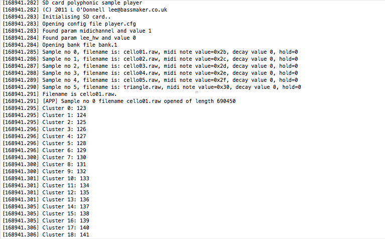
I have a problem getting the Sample Player to work with the new STM32F4. I uploaded the project.hex and connected my sdcard with some samples, and they seem to load fine, BUT I can't hear anything?!
When I connect my headphones I can hear a bit of white noise after the application is loaded, so that tells me that the audio out is (somehow?) initialized.
My hardware config:
- just the STM32F4-Discovery (no MBHP_CORE_STM32F4) with the additional jumper cable for 5V and an sdcard-reader directly connected
- I tried two different sdcards, one 4gb with FAT32 (I know I should use FAT16) and one 4GB with 2x2GB FAT16 partitions
- I know that these samples worked with a LPC17 based core
- I tried uploading MB_NG and it also seems to work fine, also with the sdcard file browser
- I connected the Audio-Out to headphones and to a mixer line-input as well, still nothing
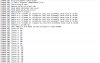
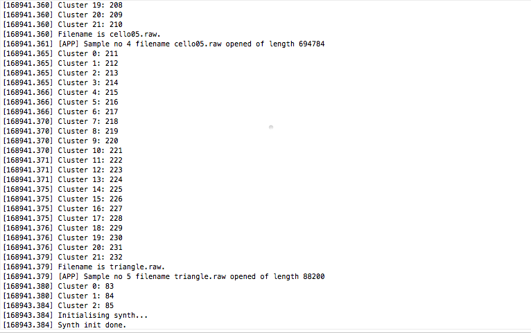
- according to MIOS Studio terminal output, everything is configured and loads up fine (see screenshots)
What I am doing wrong?
(If anybody wants to try my sdcard-files, they are here)

-
Cool, I'd like to have one too :shifty:
Quant.  |  forum name
-----------------------
   2    |  taximan
   2    |  JohnnieBee
   1    |  monokinetic
   1    |    Acul
1 | rvlt
-
Cool, seems like we are already enough ;)
Could you tell me the size of the PCB?
-
Hey Jef,
just wanna say that I'm really interested in this project. I will get a vermona drum synth this week and need something to sequence it ;)
How many people do you need to start another bulk order?
Cheers
Lars -
This is on my TODO list...
Nice !
However, meanwhile something else for you: http://svnmios.midibox.org/filedetails.php?repname=svn.mios32&path=%2Ftrunk%2Fapps%2Fcontrollers%2Fmidibox_ng_v1%2Fcfg%2Ftests%2Fmax72xx.ngcPlease try it with this pre-release: http://www.ucapps.de/mios32/midibox_ng_v1_025_pre3.zip
Best Regards, Thorsten.
Woohoo :hyper:
It's working! I tried it quickly with a "staircase sequence" sent from logic. Now I have to spend some time mapping all these LEDs (137 in my case)
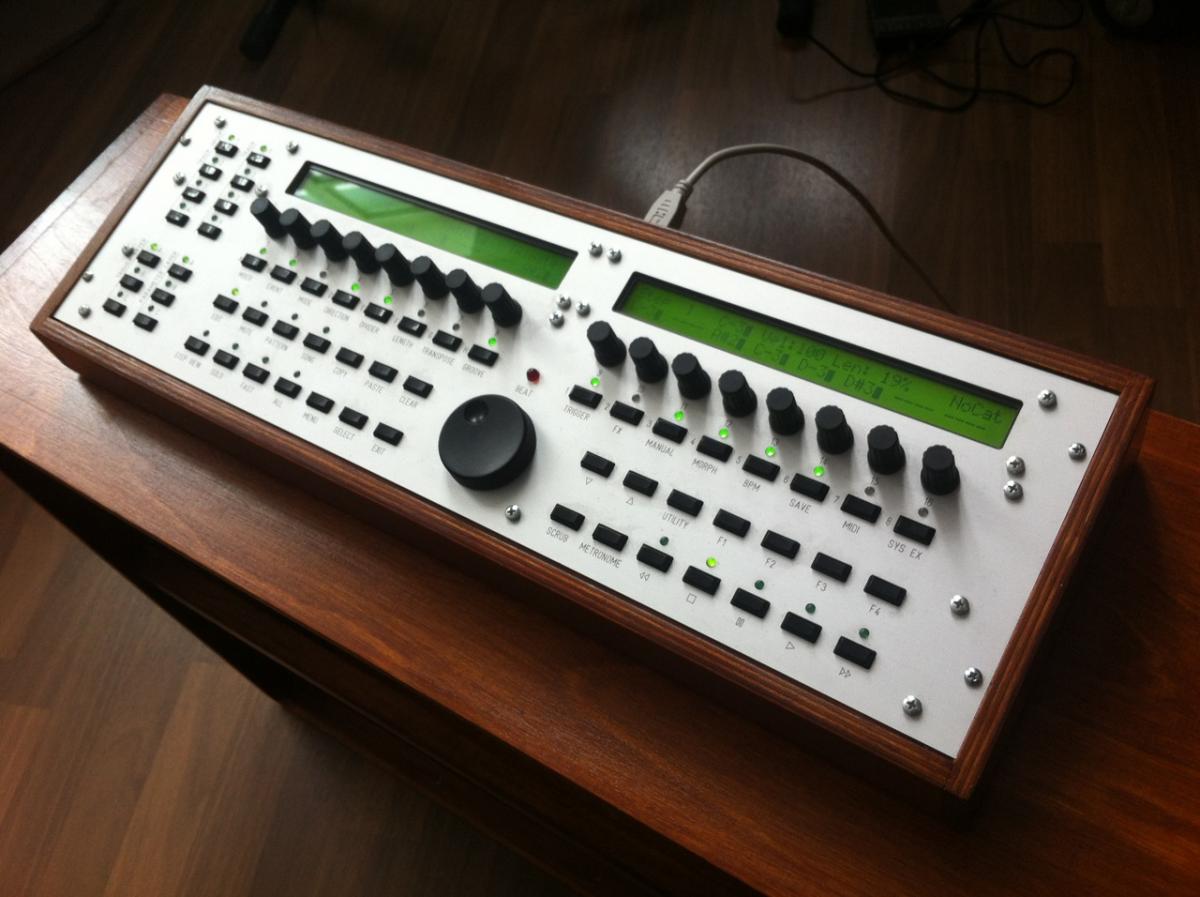
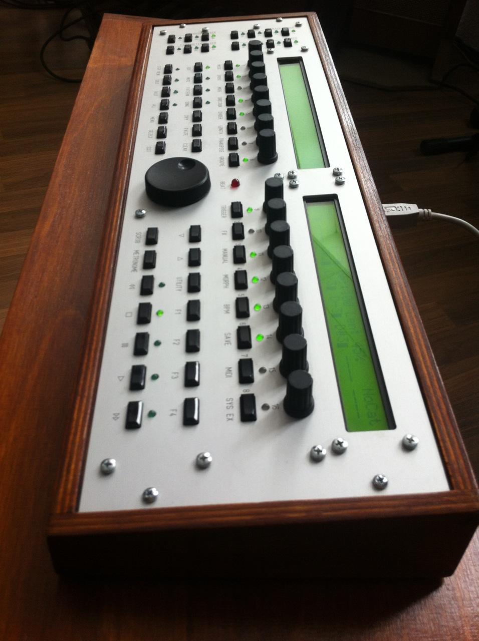
I will post some pictures when the front panel is ready.
Thank you!!
-
Re. Logic Control Mode:
Is it possible to display the SMPTE timecode / Beat on a regular LCD instead of the 7seg-digits?
-
Just a quick confirmation that the LED Digits are working. And that without any resoldering, although I had both row and select lines mirrored. Cool.
-
Hey Thorsten,
the LED digits are simply connected to DOUTs, no MAX7221 involved here. They should work once I find time to configure my NGC-file.
But there are lots of small buttons, each with a small LED above them. All these LEDs are connected to three MAX7221. They are configured in matrices, so each MAX7221 is connected to a 8x8 LED matrix (well, more like 8x7 and 8x5, since there are less than 64 LEDs per matrix).
With my PIC-core I basically used your stribe-project (with a slight modification you told me) and was able to address every single LED. The mapping was a bit "all over the place" but it all worked.
If you need more details, let me know.
Thank you,
Lars
-
   o support for LED Digits (7-segment displays).
     Configuration examples can be found under cfg/tests/leddig*.ngc
Cool, will try this asap.
btw any news on the MAX72XX support?
-
Working again.
Great!
-
Ah, ok, I just looked at the download link which still says it's for 10.6-10.8
Will try the new version later.
Thank you!
-
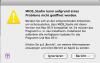
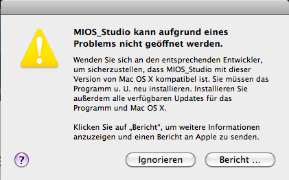
There seems to be an issue with OSX 10.6.8
Here's what I get when I start the program:
-
Working perfectly!
Thank you!
-
Thanks Duggle,
maybe easy wasn't the right word, it is actually super easy to do. I just wanted know if there is already an existing poweron-snapshot function.
re. the value-property: it doesn't work well with analog pots because the value you send doesn't correspond to the real pot.
Seems that for the snapshot dump to work you have to move an analog pot to write it's value to some kind of buffer(?). If you don't do it the buffer is empty (values=0).
-
Is there an equivalent to the snapshot_at_poweron function in MB_NG yet? I'm looking for a possibility to send the values of my analog pots and switches after startup...
I played around with the snapshots and assigned a switch to the dump function in my default.ngc:
EVENT_BUTTON id= 4 type=META meta=DumpSnapshot
this indeed sends a snapshot, but all values are set to 0.
if I start turning pots and dump the snapshot again, it works.
What am I doing wrong here?
----
For an automatic snapshot dump after boot, I could do the following:
- set up a "virtual" button id (e.g. 20) in my default.ngc with the meta event stated above
- in my default.ngr I could put this:
trigger BUTTON:20
Is this the proper way to do this? Or is there already a more easy way that I'm not aware of?
-
I ripped my wheels off an old miditech-keyboard, and another one from a m-audio oxygen8 V1 (was the same wheel assembly on both). Other than that I only know Doepfer who sell wheel / joystick combos:
I once repaired a CME keyboard which had a special potentiometer for the pitch/mod wheels, it was from "Alpha" and had 90° printed on it. With these you get the full potentiometer range by only turning it 90° (centered). You could only get it from CME support for 10,- Euro / each. Pretty expensive.
Cheers
Lars
-
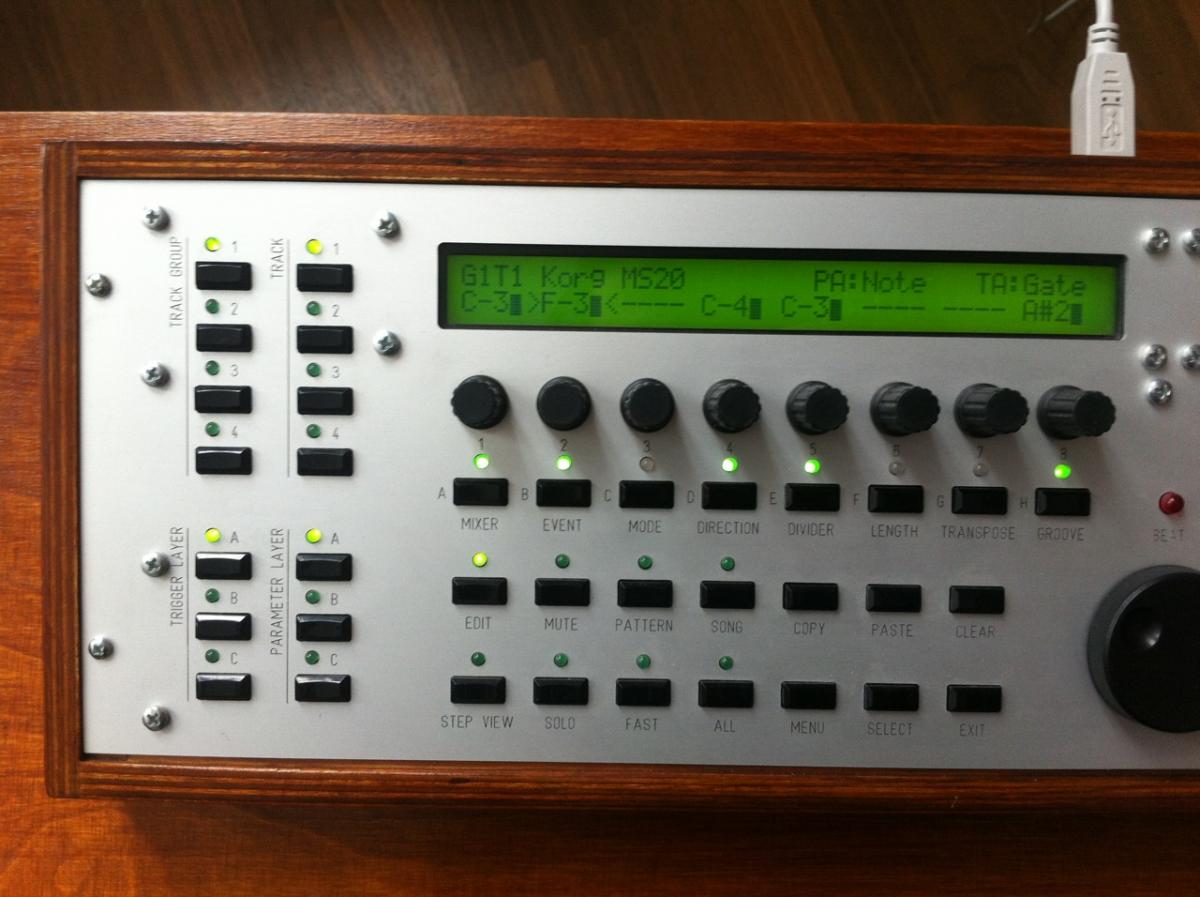
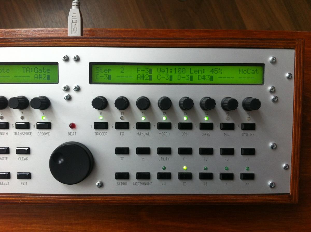
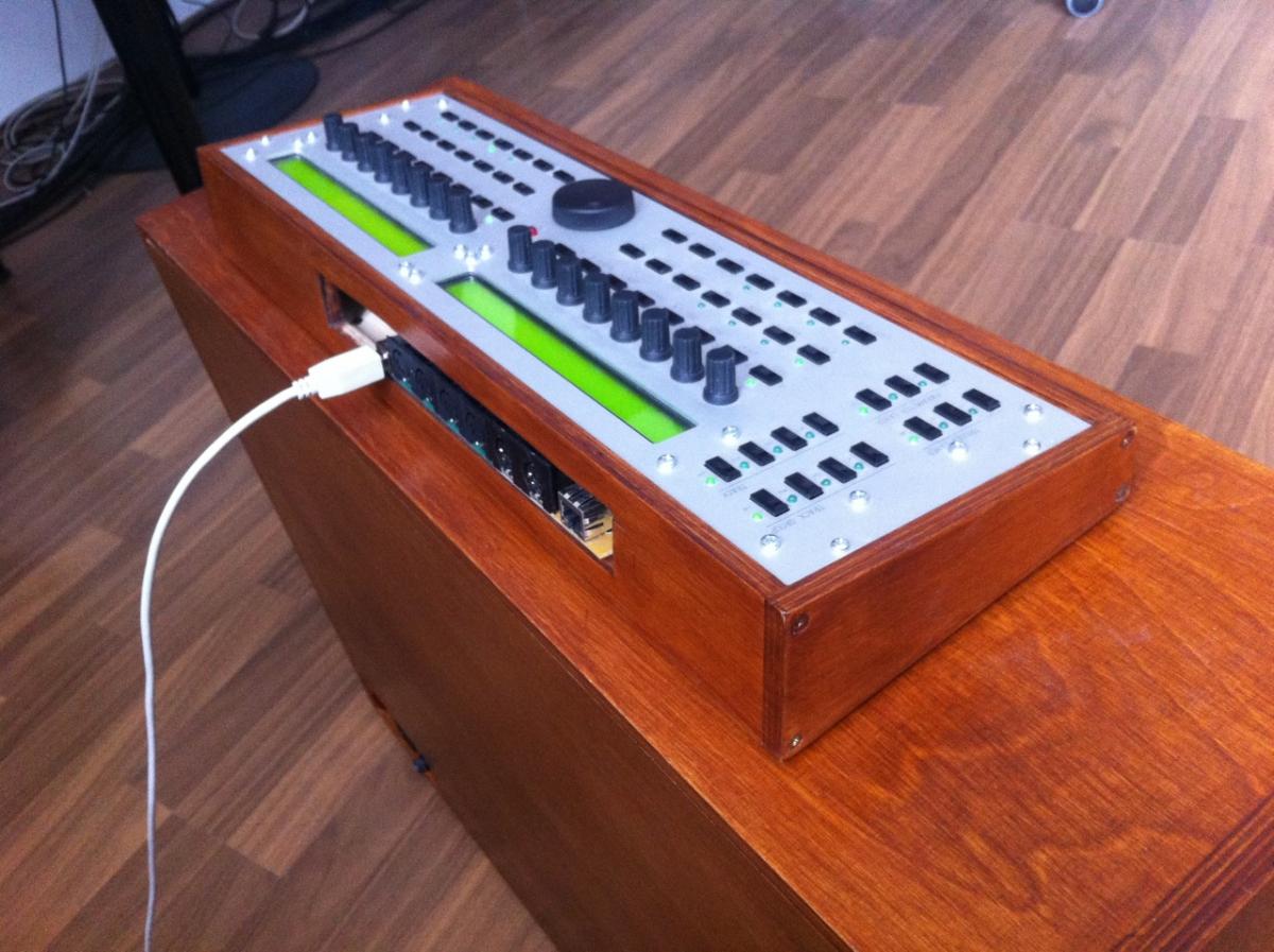
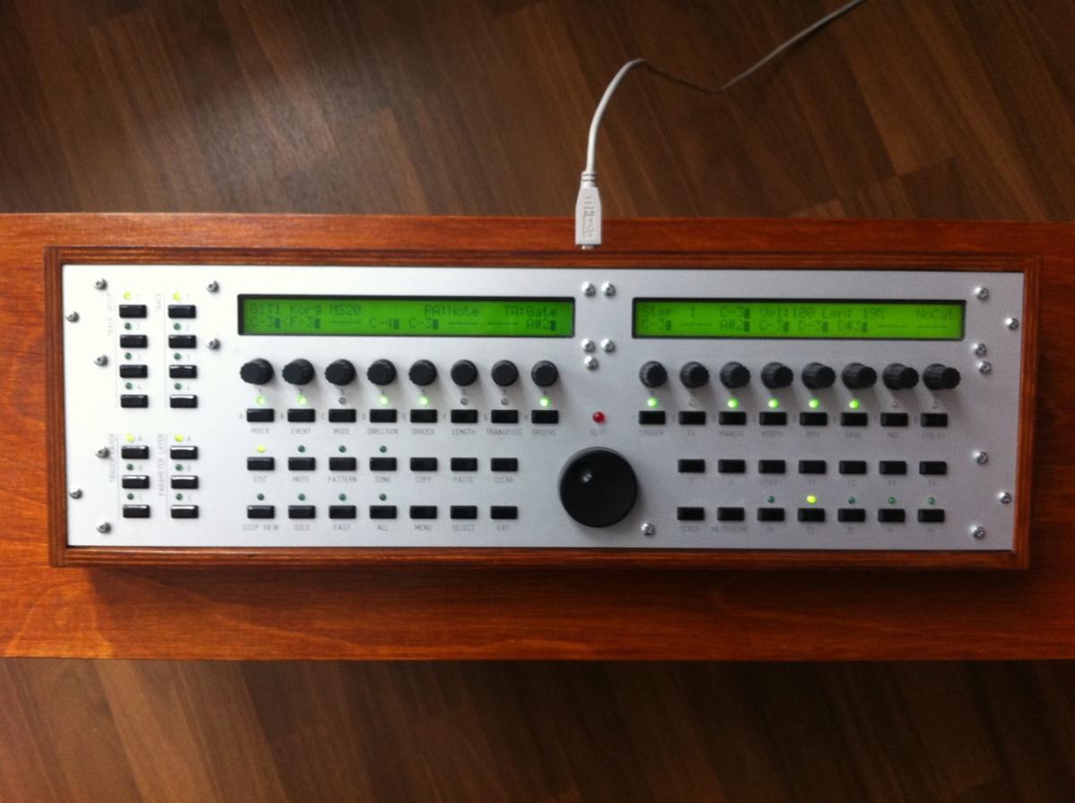
**** SOLD ****
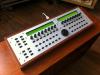
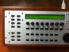
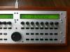
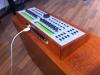
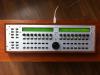
I'm selling my MB Seq V4. I know i'll regret it someday but don't use it that much and need some money for other projects.
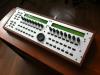
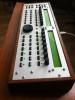
It's based on a Core32 and Smash's Control surface PCB. It has two additional Midi Outs (so all in all 2x In + 4x Out), USB, Ethernet-Port for OSC and an internal Micro-SD-Card.
I built a nice wooden desktop enclosure for it, the footprint is pretty small, think of a access virus desktop. The back panel is still missing, I was too lazy to do it, but I can make one before I sell it, or send an FPD-File.
Everything's working perfectly and is in mint condition.
PM me if you're interested.
Cheers
Lars
-
Works perfectly!!!
:thumbsup: :thumbsup: :thumbsup:
Thank you!
-
Hey,
here are the values I measured. The pinrange was set 1700:2880 before, which gave me reliable pitch values from +8128 to -8192.
I was alternating between up and down movements.
2274
2284
2271
2278
2280
2280
2269
2284
2283
2276
2268
2295
2283
2269
2286
2268
2266
2283
2287
2283
2275
2260
2273
2262
2257
2278
-
I tried the AinSer-support for the mod- and pitchwheel and it worked great.
But one small problem remains: the pitch-wheel is center-detended of course, and it uses a spring mechanism to return the potentiometer to the middle after you moved it. This is working quite well but it isn't 100% accurate, resulting in pitchbend values lesser or greater than 0.
I'd think that every pitch wheel construction suffers from these (very) small pot movements, I wonder how other manufacturers handle this...
Is there a way to solve this in software? Something like an extended deadband: all pitchbend values from normally, say -512 to + 512 should now output pitchbend=0. Would that be possible?
Cheers
Lars
-
Hey,
I did a few more tests:
1. I used a different macbook with a different PSU: same problem
2. I used an extension chord from another room (different fuse): same problem
3. I used our studio mac (mac pro desktop): all fine !
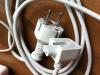
hmm … this made me wonder if this whole issue was related to grounding my macbook. So I tried the extension chord from my apple PSU, the one with three prongs (AC and Ground), and voila: When I use this I don't have any more problems.
Seems that this is a common problem:
http://www.kellerbude.de/threads/1728-MacBook-Pro-Gehäuse-steht-unter-Strom-Spannung
TK, could you tell me which cable you used when you tested this? The three-pin (schuko) cable or the small two pin adapter?
I really wonder how manufactures do it with devices which have a grounded case and a USB connector.
Anyway, I think I should start looking for a 5V PSU Class II like you suggested.
====
regarding the midi connection: I also thought about this, but when I tried it I didn't have that issue. On (I guess) most devices the midi socket's outer ring is connected to ground, but the midi cables did not have the ring connected on both sides. I tried that with three different (non-selfmade) midi cables: they all had the 5 pins connected, but the outer ring was unconnected. The "real ground" on midi cables (middle pin 2) is normally connect to ground on midi out sockets, but "should not" be connected on midi in sockets. That's why I didn't have that issue with midi, only with a USB connection.


SD card polyphonic sample player
in MIDIbox User Projects
Posted
Thanks Thorsten.
I connected my TDA1543 board (built one according to mbhp_i2s_tda1543.pdf) like this:
STM32DISCOVERY -> TDA1543
PA4 (LRCK) -> Pin#2 (WS)
PB9 (SDA) -> Pin#3 (DAT)
PC10 (SCLK) -> Pin#1 (SCK)
...and 5V, GND and audio outputs of course.
but I couldn't get any sound out of it. Don't know if this is supposed to work like that. I mean connecting a second DAC in parallel..