

fussylizard
-
Posts
280 -
Joined
-
Last visited
Content Type
Profiles
Forums
Blogs
Gallery
Posts posted by fussylizard
-
-
Interesting. However I just looked at the PCM1725 data sheet via Mouser and it says it is not recommended for new designs. Stock up now I suppose...
-
And don't forget to opt-out of the new scanning equipment in favor of a pat-down. I did that last trip just to try it and it was great. Just make sure you have money for a tip. :-)
-
Here's the 5V switcher BTW: DigiKey p/n PT78ST105V-ND
It switches at 650 kHz, so should be OK for audio purposes. Altitude has used this and had good results, so I plan to give it a go. Will report back my findings...
-
Hi fussylizard,
it surely is not the "standard" way to use the seq - but for live fun, i mostly use the 16 tracks as individual synced-unmutable sequences (like ableton clips), this is mostly always enough for a song and its variations (am not using song mode or pattern switching at all). You can organize the tracks (shift them around to bring them in a more logical order) with the new cool "track clone" feature.
Greets and have fun!
Peter
So you just do track mutes to switch stuff then?
-
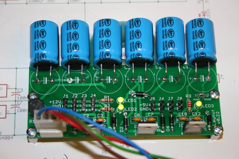
Curious as to why you have so many caps? 3 for positive/gnd and 3 for gnd/negative or something?
As far as the heat, you don't appear to have a on those regulators and that should make a *BIG* difference. Be careful not to connect your heatsink solution to both the positive and negative regulators though. For the positive regs, you should be able to even use the metal chassis as a sort of heatsink.
EDIT: Aha, I think I figured out what you're doing with the caps. It looks like you are using a multi-out transformer? If so, got a model number? I've been looking for something like that for a while.
I'm using a center-tapped toroidial transformer, Digikey p/n TE62063-ND. I can't remember if that was the exact one from the MB-808 or not...I think it uses the 18V version, this is the 15V version. As I mentioned earlier in the thread, I basically ripped off the MB-808 PSU circuit and tweaked it for ease of construction. Hence the capacitor overkill...just wanted to limit the different types to buy.
I may put heat sinks on the +/- 12V regs...I'll just have to see how they fare heat-wise. The switching reg for the 5V side should be OK.
-
interesting interesting!!
that would be my next step, to design a 4x IIC out board and have Mike make it (and to be honest, have him check it and ask a bunch of not so clever questions too :blush: )
but... if there's gonna be some ...availability.... i might be able to not kickstart my brain
:whistle:
Here's the thread about the 4xIIC board:
I'm not sure what Altitude's plans are for it. I was already ordering some stuff from BatchPCB so I ordered a prototype 4xIIC board for Altitude at the same time. Maybe drop him a PM?
-
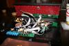
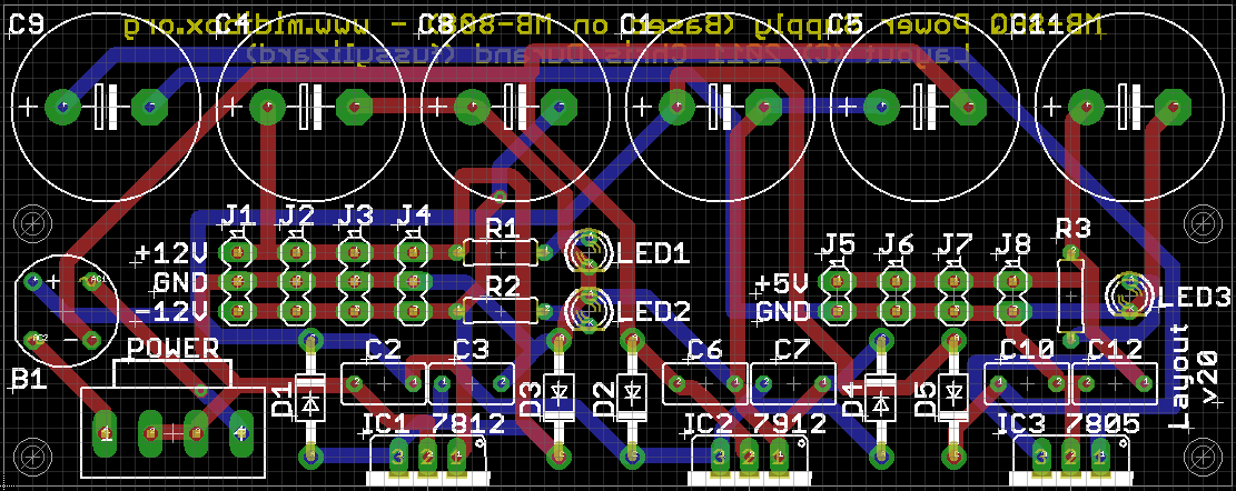
Oh BTW you can see in the pic that I mounted the caps horizontally to save vertical height in the case. That's why all the caps are along the edge like they are. Worked out pretty well.
-
Hey all,
Just a quick recap on where things are. I got the board made (BatchPCB) and it tests out fine. I went ahead and built it with a standard 7805 regulator which gets *very* hot (not surprisingly!) but I wanted to test it out. I'm going to order a switch-mode 7805 drop-in replacement to handle that problem. They are about $15 a pop, but have very high switching frequencies so I should be OK even if I drive an AOUT_NG and SSM filter (which is the plan!).
Two pics to share-
Here's the populated board:
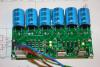
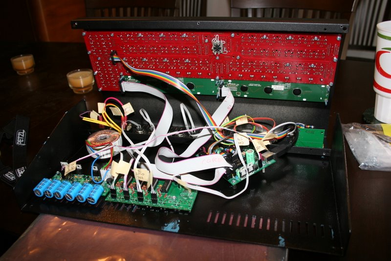
Here is my PSU board mounted in my MB-SEQ. I'm using the same case that Altitude used, though I'm quite a ways from being 100% complete on it. You can also see in that pic a prototype of Altitude's 4xIIC board, as well as my painting of the base (in-progress...first attempt was a train wreck...)
Will let you know how the switching regulator works out...
Regards,
C
-
@middleman - Interesting details on linear PSU design, thanks!
-
One more thing to ask you seq expert users out there. Given that 4 tracks are saved with each pattern, any recommendations on how to best organize things? I thinking I would use G1T1 for drums, G2T1 for bass, G3T1 for lead, and G4T1 for something other stuff. That seems logical but also seems wasteful since I am only using 1 track per group. Any tips on what has worked best for you?
Thanks,
C
-
Thanks for clarifying the intended workflow TK. That helps a lot!
I was playing with the seq some more and another thing that I think I was overlooking is that you have to save your pattern before switching to a different one. I was confused before since I thought the seq was saving all the patterns for me as I went. But the correct workflow seems to be:
- Create a pattern in A1
- Save it into A1
- Save it into A2 (copy A1 into A2)
- Switch to A2 via the pattern screen
- Edit A2 to create a variation
- Save A2 into A2
- Save A2 into A3 (copy A2 into A3)...etc.
I am getting much better results now that I'm saving, LOL!
Thanks!
C
-
Really excited to see the regular project updates on the www.eight-oh-eight.org site! Thanks Doug!
-
I'm not understanding how the seq works regarding tracks, groups, patterns, and songs. Hopefully someone can set me straight. I have read (as well as read the manual, watched videos, searched the forum, wasted hours fiddling, etc.) but I'm still stuck.
I'm basically trying to start by making a simple song. So I fire up the seq, create a new session, go to the edit screen for group 1 track 1, and get some notes playing on an outboard synth. So far so good.
Next I want to copy my synth line and make a variation. I think I need to copy the track, select a different pattern, and then paste the copied track into the new pattern and edit away, but I don't see how to select different patterns. How do I specify which pattern I want to edit? How do I know which pattern I'm editing? Do I need to be in song mode or phrase mode when creating patterns?
I tried doing copy, then going to the pattern screen and switching group 1 from 1:A1 to 1:A2 and then doing paste, but that doesn't seem to do what I want either.
Anyway, once I have multiple patterns defined, I believe I need to go to the song screen, and select song mode, and select the pattern I want for each step in the song. This part looks straightforward.
So I've been looking all through the pattern menu, save menu, and song menu, but I just can't seem to sort this out. What am I missing here?
But even without being able to create more than a single pattern, the seq has been super fun. An incredible design. Hats off to TK and the others that made this happen.
TIA,
C
-
Oh, I see on the series thing. I think the reason it is better is that the smaller caps can react faster, so you just use multiple to get the total capacitance you need.
@shuriken - 100uF is enough? I really should put a scope on it.
@all - At this point I think I'm going to go with my current version just to move on. Will let ya'll know how it turns out...Thx for all the input!
-
Not sure I follow on how to share them across rails. Can you elaborate?
Using 2200uF caps before/after the vregs on each rail is clearly overkill. I did it to keep the build simple. My earlier design had various 1000uF 35V caps, 2200uF/16V caps, 2200uF 25V caps, etc. I thought if others used the design it might be confusing, so I traded a little board space to use the largest caps needed on everything for consistency.
I've also thought about tweaking the layout to keep all the diodes in the same orientation to avoid those mistakes as well...
-
Quite right, I forgot to attach it.
@lylehaze - There are always compromises to be made!
-
Oh and a big thanks is in order to Altitude for all his help so far on my SEQ (I am using the same case as his...pictures to follow when I'm done!) and his .sch/.brd feedback along with nILS. :-) Thanks guys!
And thanks for everyone's comments so far! It would be nice to have an 'official' PSU for MIDIbox, but given that I'm a cut-and-paste circuit designer I'm not sure I'm the right person for that...
Regards,
C
-
Just going through the other comments:
@shuriken, theprof, m00dawg, etc.
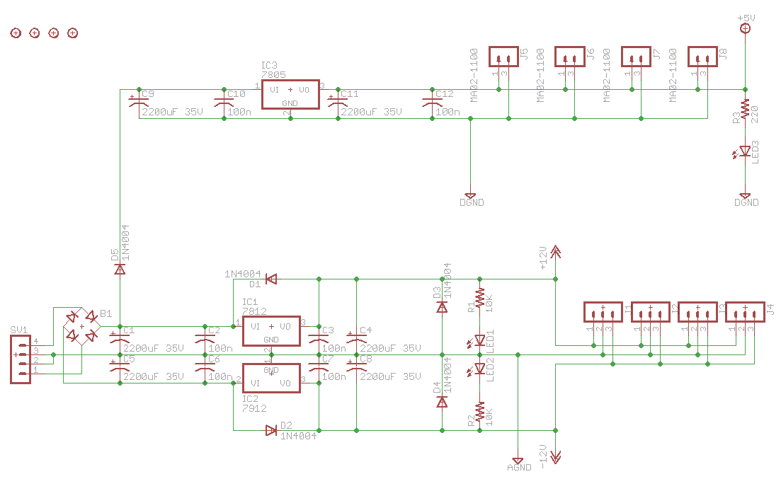
Regarding heat sinks, I agree completely. The +5V reg will definitely need them, plus maybe some diodes or power resistors (MB-808 only has the one diode).
Altitude suggested to me a while back using a drop-in switched mode replacement for the 7805: http://www.mouser.com/ProductDetail/Murata-Power-Solutions/78SR-5-2-C/?qs=sGAEpiMZZMukgiigmf73gFbB24B2O0wZ
Expensive, but no heat issues. Not sure about the noise (but it switches at 200KHz). Currently backordered, but I might give one a try.
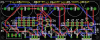
@moodawg - nice board. You have a pic of it built? Why only space for the heat sink on the 7812 but not others? I attached my latest (non-final) board for reference. (I need to add the extra diodes.)
@nILS - I think you *way* undersized the heat sinks there! :-)
-
The protection diodes are a good idea, especially if you are using unusually large capacitors after the regulators, as you are in this case. The "dangerous condition" is after power is removed, the voltage at the output of the regulator will be greater than the voltage at the input.
Why did you do this on some regulators but not all of them?
Because the MB-808 PSU doesn't do it on the +5V rail for whatever reason. :-) I agree it probably makes sense to add the diodes to the 7805 as well.
AGND and DGND should be connected in one place. and the power supply is usually that place.
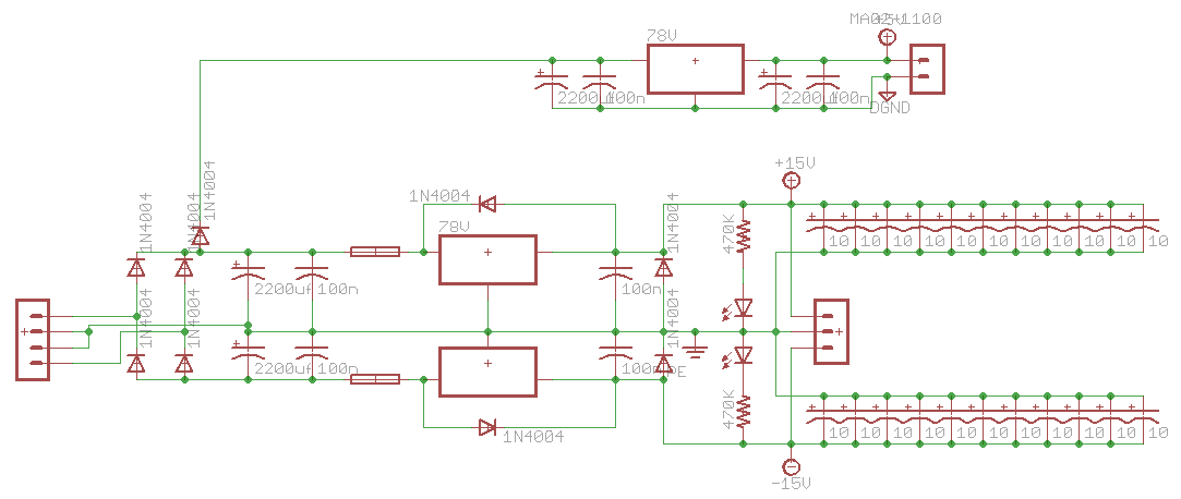
Do you have any idea why the MB-808 doesn't connect the two grounds? See the attached image. It seems weird, but that's what is in the .sch. (All the extra caps at the right are just despiking caps on each chip AFAIK...they just put them in the PSU schematic.)
D5 drops the voltage to the 7805 just a bit. this means it will run just a bit cooler, and the heat from D5 is exactly that amount. In the end, net heat is the same either way.
Ah, right, duh!
A suggestion: Instead of using 2 pin SIL for the +5 outputs, use 3 pin with the center grounded and BOTH outside pins at +5 volts. This means less chance of plugging it in backwards, but more likely to get it confused with the 12 volt connectors..
Interesting. Not sure which way is better to go, but good to think about.
-
that's a great job to have produced a so clean schem, especially for beginners
Guys, thanks for the info!
@julien - Glad you liked my first .sch layout!
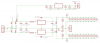
Good idea looking at the Juno-106 PSU! I could find lots of examples on the web that were just bipolor PSUs, but I didn't find anything that also had a separate +5V off the same transformer.
Interesting that they have two +5V power supplies - one for digital (top section with IC1), one for analog (bottom section). The analog grounds for the +15V, -15V, and +5V are connected together per lylehaze's comment I think (see vertical line just to left of the VR2 bold label). Presumably they are separate for noise reduction.
The digital +5V, however, seems to come in on some separate winding on the transformer so I'm not sure what's going on there. There's also some extra circuitry above IC1 for reset that probably just triggers a reset pin on a microcontroller once the PSU is stable after being turned on.
Around IC2 there are some extra transistors and resistors that I don't know what they are for...will have to lookup the data sheet for that part if possible.
Doing a PSU board for others would be great, but I'll need some design help (<trek>I'm a coder not a circuit-designer, Jim!</trek>). And in the meantime, I want to finish my MB-SEQ. :-)
-
You just need the red plastic sides and you'll have an "optimus prime" MPC-style MB-SEQ!
-
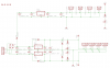
I'm trying to design a PSU board for my MB-SEQ w/ and AOUT-NG and SSM filter. I swiped the basic schematic from the MB-808 and thanks to Altitude and nILS made some tweaks and simplifications, and I also tried to make it easy to build (e.g. just using 2200uF filter caps for everything instead of more exact cap values- one type of electrolytic cap means less confusion, etc.).
If it is not clear from the schematic, the jack at the left is for a center-tapped transformer, and there are multiple SIL headers for output power.
I've built it on a protoboard and it seems to work, but I had a few questions I was hoping someone might be able to answer:
1) Do I really need the protection diodes D1/D2/D3/D4? As far as I can tell this comes from an old app note from the 1970's to protect the regulators, but modern 78xx/79xx regulators are pretty indestructible and I don't see these in many other designs, so can those be removed?
2) Can I tie AGND and DGND together? It seems like I should, but I didn't see that in the MB-808 PSU so I thought I should double-check.
3) What's the purpose of D5? It was on the MB-808 but I wasn't sure of its purpose. I'm guessing it helps prevent some sort of current flow between the 5V and +/-12V sections?
Thanks for any insights!
Oh and BTW I know I can probably buy something off-the-shelf that would work for me, but I wanted to make my own circuit board in Eagle and get it made (at BatchPCB). It's been fun so far. Once the design is proven, I can post the .sch and .brd files. I could probably be talked into a mini-bulk order for PCBs if enough people are interested.
Regards,
C
-
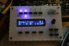
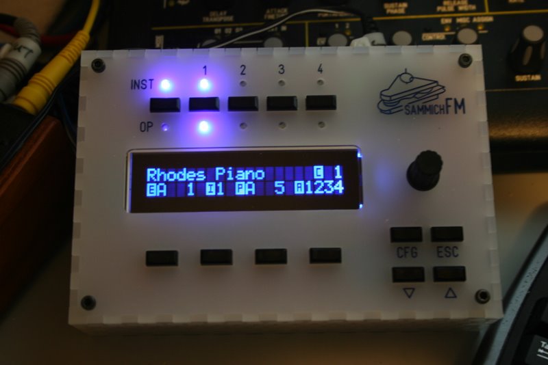
Here's a pic. As I suspected the exposure time completely changes how it looks. I wish it were half as bright as in the picture. Ah, well. It's good enough and is a nice display so I should probably stop whining about it and start using the sammichFM!
Thx,
C
-
Will do tomorrow. Glad to hear your pot does nothing either. I compared the brightness to my MB-6582 and to be honest it is about the same as the CrystalFontz display I used. However I have some very nice Optrex 2x40 displays (from the bulk order I ran a whIle back) for MB-SEQ and they are much brighter.
It's probably fine but I'll post a pic that hopefully will help.
Thx,
C
Prototyping Board
in Design Concepts
Posted
I've used BatchPCB and they were great. I've not tried anyone else.