tonyn
-
Posts
203 -
Joined
-
Last visited
Content Type
Profiles
Forums
Blogs
Gallery
Everything posted by tonyn
-
Yes, decisions decisions. Yes I have thought this out and with the old stop tabs you may not easily cancel them out with the cancel piston from the virtual organ software, etc., unless everythign is computer controlled with momentary buttons and LEDS for indicators. Yes, the program change is easily done with the midibox128.ini, no need for asm code. The dout part(MIDI-IN in midibox128.ini) is also easily configurable in midibox128.ini for Douts. The Douts are where you can latch the outputs from the virtual programs by adding LEDs and relays. If you use the old stop tabs, with dins only, you will also need to build separate relay circuits that are isolated from the Dins to activate your leslie motors. Get double pole double throw relays, and one set of contacts go to a din, the other to motor drivers. You could of course build a Doutx1 circuit for just a couple of relay circuits. But since I pln to activate LEDs for ALL stop tabs, I will just go with Doutx4 boards from avitshowtech(but breadboard a doutx1 circuit first to test it out). I plan to use the Douts to both drive LEDs and close relays for that part, and latch them on/off. But the piston cancel, etc., maybe trickier to program in Jorgan, etc., if you don't use momenatary for the stops. Also, don't forget, if your organ has these like mine: Reverb pot, etc., that if you want use of those you need to use an anolog input to the stop core and that is done in asm. I may also want to have a physical LED meter for things, and that would require Aouts too. I'll be breadboarding these things first, to see how things work best. I'll post my progress and let you know what I find.
-
Problem getting edited midio128.ini to work
tonyn replied to RVBottomly's topic in Testing/Troubleshooting
Yes, that's the one. Great. Glad it worked for you, and to help a fellow Baldwin Organ owner. For some reason MiosStudio and Midi-Ox have problems uploading syx files to the PIC. I learned the hard way by trial and error. The swell pedal is a bit trickier to program. But you can -
No suggestions on a good free CAD program? Oh, well, guess I am on my own to find one that suits me. Note: Yes, I could use the old stops and pistons, etc. But first off: When a core scans the Dins for the stops, and they are non momentary, I am afraid that the Midi signals will overwhem the virtual organ programs. That's like the swell pedal: I had to turn the threshold up in Jorgan else even touching the swell pedal caused it to almost lock up Jorgan. Second: The pistons may not be able to cancel out stops that are physically active, unless they are compltely controlled by the computer. So the stops and pistons need to be momentary with Dins. But how would you know a stop is active? Douts and LEDS. Thus unfortunetely I can't use my type of stops, since it seems too hard to try to make them spring back etc. Organs with tab type stops maybe better with putting momentary push buttons behind them. What I may do is see what type of stop boards my organ guy has. If he has a complete one from a theater type organ that can easily be changed to momentary, I may take measurements and see if I can change out stop boards. LEDS can be installed above the stops to indicate an active stop(easily done). The pistons should be easy. I can just cut the old piston tops off, attach them to push buttons, and make a panel for the push buttons somehow, and wahla. Breadboarding time too. And guess what? I do have a nice push button board with 61 push buttons with which to test out a stop type board with! :) At least I can hook up a couple of dins and a core to it and program program changes for stops into midibox and try it out, instead of constructing a whole new one. I can then try out LED and relay circuits, Douts, etc. Gives me a testing board to work with before committing something to the organ! So my push botton board experience is not wasted.
-
Problem uploading 1.9g with diffrent PIC header ID's
tonyn replied to Altitude's topic in MIDIbox Tools & MIOS Studio
Maybe it's just the app you are uploading with. My cores are version 1.9, and I have had problems uploading syx files. Are you uploading hex or syx files? MiosStudio and Midi-Ox seem to do fine with hex uploads, but have problems, for me at least, with syx files. I finally had to use the Sysexbox app for syx file uploads to the 1.9 cores. It could be that MiosStudio and Midi-Ox are looking for a request or something that isn't syncing with version 1.9 of mios for the syx uploads, or? -
Problem getting edited midio128.ini to work
tonyn replied to RVBottomly's topic in Testing/Troubleshooting
No. Most likely your new syx file is just not uploading to the core. What you are seeing is the default hex file configuration, which will generate notes. But to reconfigure that, you upload a new syx file. Your syx file is just not uploading with Midi-Ox I'll bet. I too had problems trying to upload syx files with Miosstudio and Midi-Ox. It may look like it's being uploaded in midi-ox, but it's going to nana land instead! Try to upload your syx file with the Sysexbox 128 app instead. I don't have the link to it but if you look it's here somewhere. You are almost there! Let me know how it gos when you are able to play your first reconfigured notes! I loved it when all of the notes I reconfigured played right in Miditzer the first time. -
As I stated this next part of my midification process will mostly take place with computer design and planning. Then I'll breadboard some of it for testing before commiting it to drilling and cutting into the stop area of my organ. The leslie motor is easy, just need to keep the old organ's motor control circuits, and use relays to activate them. For amplification I have a couple of routes: Use the old amp and try to make sure the inputs don't blow up my computer. I may just design new amps, but use the nice big transformer from the old amp. But gut out the rest of the old amp. Or just use 3 amplified speakers and gut them out of the speakers, etc., and use them to power the leslie and other organ speakers. So it's not hard. What I need to do is decide what all I want for stops and layout. I'll take measurements and see what type of material, etc., I want to use for the stops. Acrylic is my choice of favorites. Or I could even use the old stop covers and somehow make them momentary by installing push buttons behind them, etc., then LEDS above them, etc. I'll use photoshop to design the look of it to look at, and virtually test in Jorgan. But I'll need a simple, free, CAD program for the physical layout of the stop board. I am not taking this to a machine shop, so all I need is an easy and simple CAD program, that is accurate for measurements, that can print out to multiple pieces of paper, to use for templates. Plus it would be nice for it to output to jpg, so I can use that for Jorgan Skins, etc. Anyone have any suggestions?
-
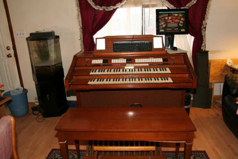
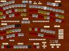
Now my Swell Pedal also works in Jorgan! I just had to set the Change Message data 2 to: "set 127 | get value" in my disposition, and set the threshold to "0.05". I am using a fluidsynth version of Bruce Miles Wurlitzer 260 (I have the Great and Solo mapped to channel 1 for my Solo keyboard). I also reconfigured midibox to send the swell out on channel 13 (easy to do as I said with my core chain, I just upload to the ID of the core I want to change). In midibox channel 13 for the swell is "0xbc" To set channels for the swell pedals in Jorgan you just change the status from 176 to 176 + channel# For channel 13 it's "188". Data 1 = "7" At least that is what I have set for now. BTW: My first class for this semester actually starts January 26. So I have a couple of weeks yet to play with the organ. Right now I am working on the virtual organ software, photoshop, etc., and dispositions I want for stops, etc. Since I like all of the bells and Whisles of the Wurlitzer 260, I most likely will use one of the Wurlitzer 260 dispositions for the sound fonts, etc., and just design it into my organ console's stops, as a start. Once I get more of a hang of Jorgan, I can then add neat features from modern organ examples, and think out how to to it physically too. I like the full customization of Jorgan! Then, to switch over to true sounds, I will play with the free version of Hauptwerk, etc.! Eventually I want to start doing some virtual organ coding myself, and make a nice custom GUI shell for the virtual organ programs, maybe in Java(cross platform, so this is what I want to consentrate on) or Visual Basic, etc. I haven't worked with Java other than Java script for websites. But this semester I'll be taking Java at the college to learn more about it, and to apply what I learn to this! I will then change my organ computer's operating system over to Linux(this I have worked with before, so I know linux). Right now it's crappy Vista(I hate Vista, but it came preinstalled on the organ computer). I may change over my motherboard for my organ computer next month too! I want at least a dual core(I thought I got one but it isn't), with enough expansion slots for at least 3-4 sound cards, and a side buss to make it 1 unit high so it will fit nicely in the top of the organ. My cards right now maybe too high. Or get a good integrated motherboard with good sound, and figure out how to send out to the different channels of the sound. I am using fluidsynth right now with the integrated sound, so I could do something like that, and have no cards on the motherboard! Here's a screen shot of my current Jorgan Wurlitzer 260 console. This is pretty much untouched and is the default. I am playing this now with my organ, and to me it actually has better sound than Miditzer 216! I'll also make various consoles of modern organs to map to my physical stops, etc., using photoshop, etc. When I am happy with a console layout for Jorgan, I'll then make it physical. Until my stops are physical to the virtual organ programs, I can use the touch screen for various virtual consoles! Even after that, I can always call up virtual organ consoles for more organs! Love the virtual stuff!
-
Yes 99% isopropyl alcohol does the job, cheaply too. I found it at a K-Mart pharmacy. You may have to ask the pharmisist to order it for you though, but it's non prescription. I like to mix a little Acetone with it to help. You can get small bottles of 100% Acetone at Walmart, in the women's nail polish section. Then get a toothbrush and a can of compressed air to blow it off imediately (available at an office supply for dusting keyboards). That's for whole circuit boards. You can use a cotton swab for small areas. Cheap and effective.
-
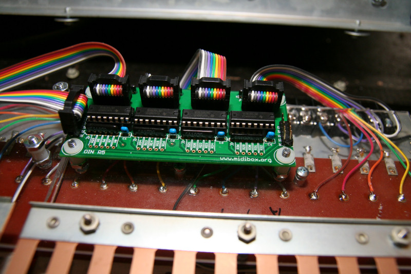
If you order the latest versions from avishowtech, they have dual headers. So don't forget to get some 10 pin IDC connectors for the dins and core. You will need 6(get a couple of extra just in case). I found that the IDC connectors are easier and cheaper than trying to crimp individual female header connector pins. You don't need a crimping tool either, a small cheap vise will do. Plus get some nice 10 pin ribbon cable too. Feel free to check out my thread to get some ideas on how I did it. I also show how I crimp the IDC connectors using a vise.
-
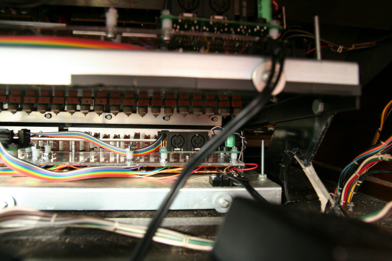
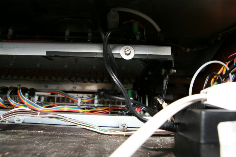
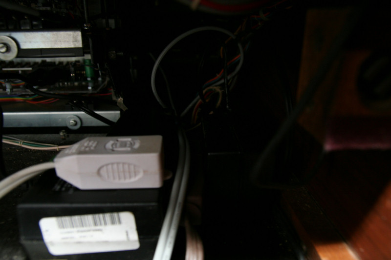
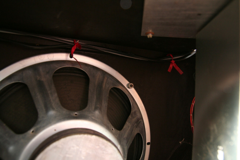
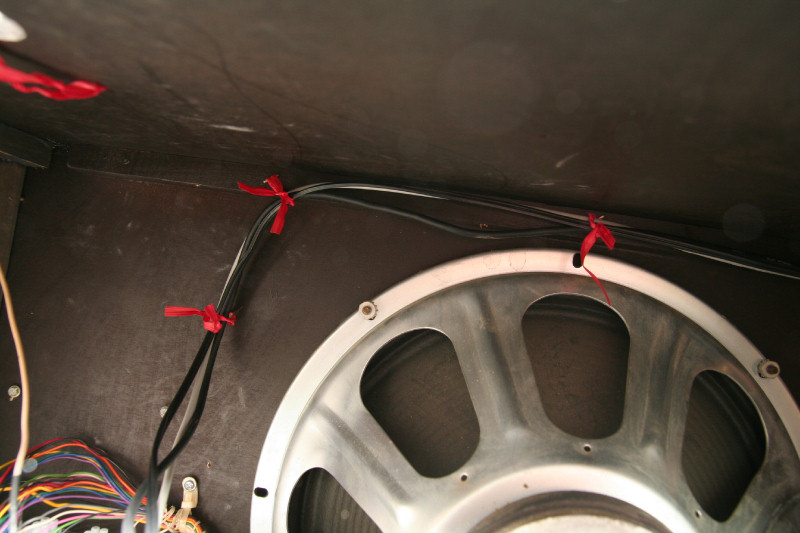
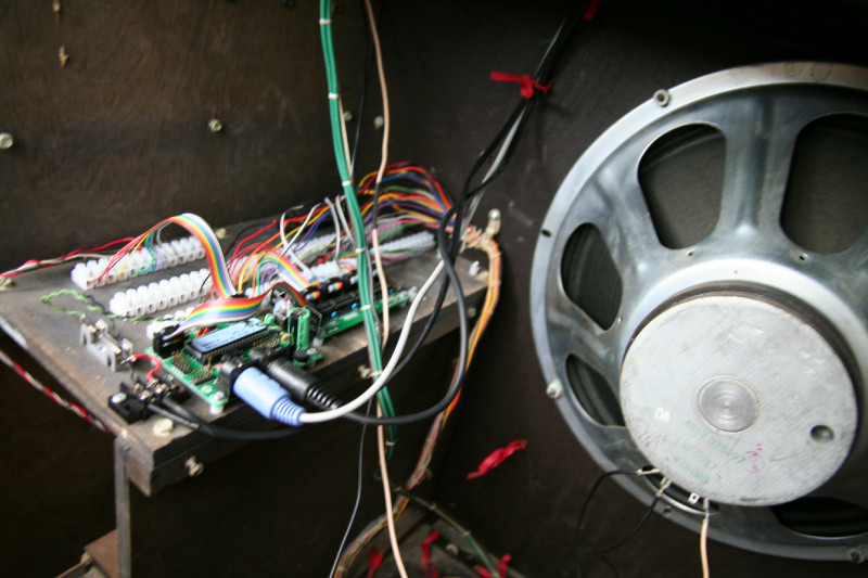
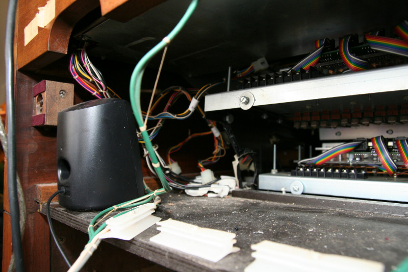
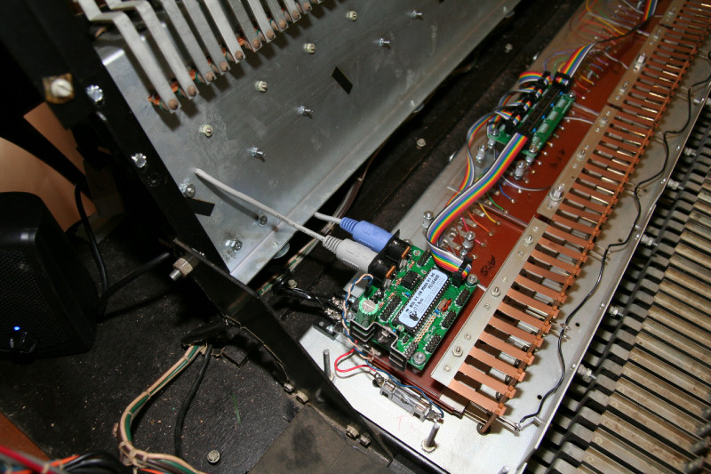
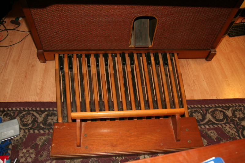
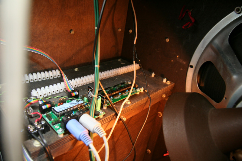
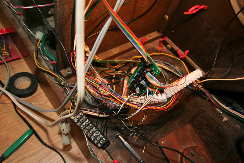
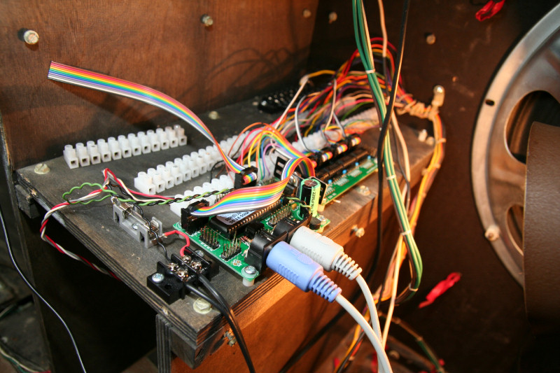
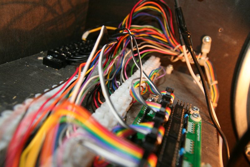
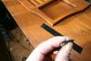
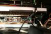
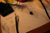
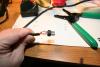
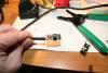
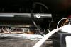
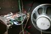
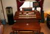
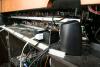
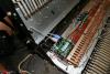
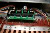
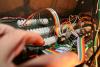
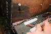
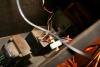
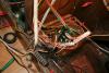
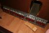
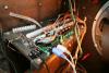
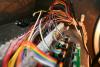
Well I am finished, for now, and won't be back at it for maybe a week, or when I have time. Tomarrow I need to concentrate on going back to school. I found these rubber things (left over from the front of the Solo contact board to protect wires to the old circuits on the front of the Solo contact board), that I put on the back metal of the Solo contact board to help with NOT cutting the midi and power cable wires from the Accompanment, when it is tilted up. I repaired the midi cable from the computer, made 2 custom midi cables out of one 5 foot one, to daily chain the cores, and tied the cables up a bit. I'll plan out the power strip, etc., later. I do have the organ closed up and playable, and the computer speakers are sitting inside the organ, down by the organ speaker area for now. The keyboard can be moved to behind the sheet music holder when I want to play, for now. But I am still thinking out how to have a shelf for it and the mouse (although the screen is a touch screen, a mouse still comes in handy) swing in and out of the way, etc. I also have my organ sitting far enough from the window so I can still work on it from behind, etc. My keyboards, pedalboard, and swell pedal are all midified, daisy chained, and work well in Miditzer! But I am still trying to figure out how to configure the swell channel in the Jorgan Dispositions. Since the cores pass signals down the chain, the computer input is to the Solo core (for now, eventually the first core that takes the input from the computer will be the stops core), and output is from the pedalboard core. I can also reconfigure my cores from one input from the computer without changing or removing any cabling. I just upload to the ID of the core I want to change! The cores all have a unigue ID from 0(stops), to 3(pedalboard). So, now that I know how to change the channel of the swell, I may map it to another channel that works better in my Jorgan dispositions, etc. I do have 4 more Din kits and 1 more core kit for my stops to handle up to 128 stops! But I will need 4 Dout kits and maybe an Ain and Aout for the stops, etc. Those I will order next month. In the meantime I can do some breadboarding, etc., to see what I will need. Here's a bunch of pictures for you:

-
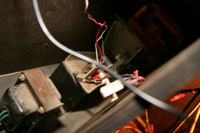
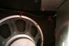
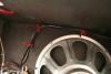
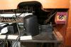
I just called my organ guy to tell him what I will be looking into next: The leslie motor control circuitry The amplification circuits He will be emailing me some schematics on those. I also told him about the transformer I saw near the swell pedal: That's for the organ lights. For the leslie motor control I will use the Douts(need to order them), to control relays. I may need 2 sets of relays, 1 set of low powered ones for the Douts, and the second to control the motor circuits. I'll need 2 Tremolo circuits, since there are 2 speeds, 2 motors. Instead of trying to reuse the old amplifier, I may opt for new powered speakers instead. My 10w computer speakers, that are temporarily placed inside of the organ, do have good volume , enough right now for my living room that I have them turned down! So I could look for 3x 10w-50w powered speakers instead, and just tear out the speakers, and wire in the organ speakers instead. This would save me a lot of headaches for me too with trying to deal with the old amp, blowing up my computer, and having to design peamps for it, etc.. Plus, maybe I could put 16 10w powered speakers(160w total) in like that lowery had this way, each one with a filter for a certain frequency range for different instruments! :) What looked like a tranformer under the organ is also a leslie motor(he told me there are 2). I asked him about piston covers and stop covers. Since I already have 122 push button switches, I don't need full stops nor pistons. I just need nice translusient stop covers that hinge, that I can put LEDs behind with my push buttons. He said he may have some from lowery organs. The full push button type stop tabs from the newer organs he said had that cheap resistive contacts behind them! I dont' want that, but if I can use the covers, that will work. The pistons I can either use the covers I have and make a panel mount for my push buttons, or see what he has. Or maybe I can modify my pistons with springs, etc., to be momentary, etc. Like I said these parts of the midification process will take me some time to design and do. But I wanted to call him to let him know ahead what I will be needing next.
-
The rest of this weekend I'll be planning out the Midi cabling , power cabling, power strip placement, UPS battery and circuit placement, and computer power supply placement. The battery and computer power supply I hope to put on each side of the keyboards in back, since, hopefully, there is enough height for those there. The power strip in back behind the keyboards. I'll run most of my cabling on the left side of the organ, since I have my cores on that side, it makes sense to run the cabling on that side now too. Plus the hole that is near the pedalboard circuitry comes up in the back middle area, where I want to put the powerstrip. But there is a hole on the left side with plenty of room to run cables down to the amplifier and pedalboard circuitry areas. After that is all done I'll be figuring out how to make the pistons into momentary push buttons, and wiring them up. Pretty soon I'll be re-designing my stop area console and planning out the Midi circuitry. This will be designed on the computer (I'll design a virtual console to play with in Jorgan, etc., and if I like it, it will go physical), so I can see what it will look like before I physically commit. I'll also be looking at the old organ Tremolo(leslie motor), circuits and control, and amplification circuits to see how to get them working too These parts will take me a lot longer, since next week I have to start looking at my schooling and won't have much time for the organ. But at least it will be completely playable with the virtual organ software, using the touch screen for the stops, and 10w computer speakers for sound output!

-
Well, the din is fixed(resistor network oriantations make a difference). But now I have a cut Midi cable from the computer! I have no idea on how that happened! It could be from the metal on the back of the Solo contact board(it's a bit sharp). So I'll have to make sure that when the Solo contact board is turned up and down it has clearances to not to cut into anything. I am making a couple of Midi cables today anyway to daisy chain the keyboards and pedalboard. So I might as well repair that now too. I will also leave the dust covers off until I am pretty much done with the organ. Then I'll make the cutouts for the power, Midi cables, and aux output from the keyboards (I have 3 spare inputs per keyboard midi circuits from the dins, which is 6 total, enough to use for my pistons). The dust covers just attach with clips in front and screws in back.
-
Well I have been troubleshooting that bad Din circuit board. I ohmed out the traces, and even swapped out the ICs. Actually all 4 jumpers, pin#4 of them cause shorting to to pins of All ICs. The reason I didn't initially find it with the 4th jumper was when testing it with the pedalboard, which only had 25 contacts, pin #4 of J6 was for note 29. But testing it in the accompanment keyboard showed that was bad too. Pins# 4 of these jumpers use the first pin of the resistor networks and is close to the caps. I looked for shorts there too but couldn't find any. My only thought now is that I may have the resistor networks reversed, which shouldn't matter. I did put these in the reverse of the first dins which were all good. If that isn't it it maybe the caps. Those are also in reverse, but this shouldn't have mattered either. I hate the idea of desoldering these components, since I don't want to destroy them or the board in the process. But there is not much on these boards, other than the board itself, that can be bad. My soldering I closely inspected, and it seems all good.
-
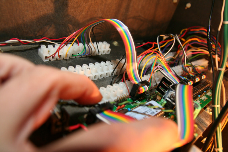
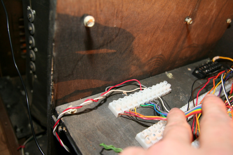
Note: Wiring to the terminal and barrier strips. The ribbon cable wire is 26 gauge, and stranded. The terminal strips I have those wires wired to, only accept up to 22 gauge. So, to make the 26 gauge wire wider, and to help it from tearing the strands when you tighten it in the terminals: I first stripped the ends back to 1/2 inch, and turned back the ends to have 1/4" doubled up ends. I then tinned the ends with solder. To do the runs I cut back each wire from the cable, starting with the wire that has the longest reach to a terminal, 1/2" 1/2" is about the distance between terminal connections so it makes a nice run. I made sure that the longest wire length had some play, which is inportant too. All of the black screw terminals(I, or Radio Shack, where I got them from, call these barrier strips) wires were also stripped 1/2", and have doubled and tinned ends, and inserted to the left of the screws before turning. (this way the screw twists the wire tightly around the screw when you tighten it clockwise). I tried to allow enough play in the wires so nothing was real tight. This is inportant, so over time they won't break or pull out! I also used strain reliefs where I could, to help too. It's these little things that are inportant too when doing a project, if you want it to last and be professional.
-
Well I got what I wanted. Kind of in a strange way (I'll delve more into the understanding of the asm and C coding of midibox later). I downloaded that guys example files. Then I opened the main_swell.asm file. If you search in his files for "psz" you will see where he inserted code for the swell pedal. In his swell channel part, here is what I edited: The first byte determines the channel. The channels is 0xbchannel Channels 1-16(0-f in hex). I wanted channel 16, so I changed it to 0xbf. It was 0xb0 for channel 1. I then loaded his project file into MPLAB, and had it build a hex file, setting it as an absolute build. Then I used his scripts to convert to syx. Uploaded that to the core. Then to change the pedalboard note channel and enabling midimerge from my midibox128.ini configuration I made into a syx file, I uploaded that syx file second to the core. The core took both syx files , the first setting the swell and channel, the second setting the pedal notes, channel, and enabling midimerge. It seems that if there is something in the first upload of a syx file to the core, that isn't in the second syx, the second won't overwrite that part. But it did overwrite the din codes, and enabled midimerge. So you can take advantage of both(the ini for din/dout, and midimerge, etc., and MPLAB for other, like Ain, etc., that isn't in the ini) This works well in Miditzer, but Jorgan needs a bit of tweeking to get it to work it seems. I can't seem to find the channel settings for the swell pedals in the disposition I have right now. But at least I know it all works and I know how to change the channels. That is all I need for now. I now have the Solo, Pedalboard, and Swell ALL fully working, midified, merged, and playable in Miditzer! All I have to do now is fix that din, put the Accompanment back into service, and wrap up it up for the keyboards, pedalboard, and swell!
-
Well I do have the Main and Solo swell pedals working in Miditzer with the organ's swell pedal! Which is what I was after. But I had to change the settings in Miditzer(set the Aux to channel 1) to use channel 1 for the swell. The pedalboard does work now on channel 14, as I wanted, but the swell is on channel 1. But I don't know what I did to get it all working right in code! So a night's sleep will refresh my mind as to what I did. I want the swell on channel 16, and the pedalboard on channel 14. I am working with the asm files and MPLAB, compiling to hex, converting to syx, and uploading that to the core. But at least I know it all works!
-
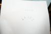
Almost there! I downloaded that guys examples. He had a swell syx file in his zip, so just for the heck of it I uploaded it to the core. I do get volume messages in midi-ox from moving the swell pedal! Here's a snapshot of the output from the swell pedal in midi-ox: I then tried it in Miditzer, and although the pedalboard still works in Miditzer(but now it's on channel 1, which is what I have for my Solo, so it plays the Solo keyboard when I play the pedalboard), the swell doesn't(as you can see it is sending on channel 1 too). It does work, just not sending out the right codes(most likely the channel is wrong) for Miditzer nor Jorgan yet. So a little tweeking of code and I should have both swell and pedalboard fully working in Miditzer and Jorgan, etc.! Any ideas why this code doesn't work for Miditzer? What channel is the swell for Miditzer? It must just be the channels. I downloaded MPLAB(it's free) Now I'll look at some example C code and asm codes for midi128, and get acquanted with MPLAB. I think I used that IDE a while back, but am a bit fuzzy on it. But I have programmed in Machine Language, Octal, Hex, Assembly, C, C++, etc., before, so it shouldn't take me too long. :)
-
It looks like I'll have to use MPLAB, to recompile a hex file with the ain codes for the swell! I got the info off of the virtual organ site forum thread here
-
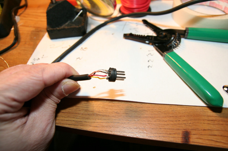
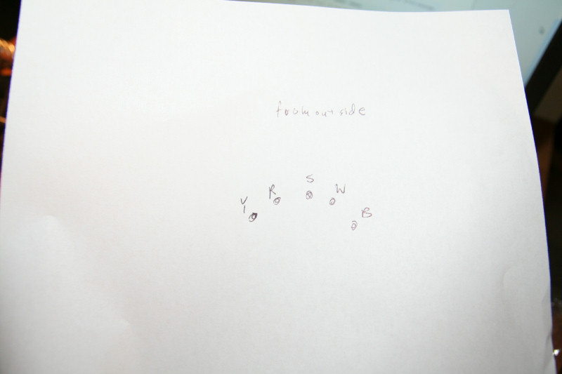
OK. I have the swell pedal all wired up. I have it wired correctly too(I hope). When you push the pedal down the voltage gos from 1v-5v Pin 10 on J5A of the core is pin 10, black, and ground(vs). Every other pin on J5A is a ground(2,4,6,8,10) Pin 9 is +5v(vd), or white wire. Pins 1,3,5,7,9 are in this order A3,A2,A1,A0 Both sides of the swell pot go to pins 9,10 of J5A(+5v, ground). The red wire or wiper, middle wire from pot gos to pin 7 of J5A(A0, purple ribbon cable wire). Now to code the core to output the correct codes for A0 for a swell pedal.
-
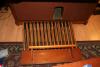
We now have a fully midified, fully functional, pedalboard! I fixed the solder connection for pedal #2, and put everything back. But I had to also swap out the din with the one from the accompanment, since pin #4 on J3-J5 plays double notes. It's easier to pop in a din into my keyboard midicircuits than to do it with the pedalboard one (although the pedalboard midi circuit is easy work on and to get to, I have to get behind the organ). It's not the midibox code it's something wrong with the din. I visually looked at the traces and couldn't see anything. Plus I visually inspected the IC insertions, and pins, and nothing. I will ohm it out next. If that is good, I may have to swap ICs out with spares from my din kits for the stops (I have 1 more core kit and 4 more din kits for the stop midification part). I may have 3 bad ICs. It's a consistant problem across 3 ICs, so it could be 3 bad ICs, or resistor networks. But that can wait until later. Now to get the swell working...
-
The pedal #2 issue wasn't as easy as a contact spring wire out of place. So I had to remove the pedalboard contact board to troubleshoot it. But, fortunetly I designed things so I can easily do this! I just popped out a din from my Accompanment board(easily done), so I didn't have to remove the din from the pedalboard( a bit harder to put back). I took a longer IDC cable from my Accompanment too, to use for the core to the din. Unscrewed the terminal strips and strain relief to pull the pedalboard cable down, and pulled the contact board out a bit so I can work on it. It's all connected up to Miditzer so I can push the tabs to play the notes to test, etc. Update: I found the problem already! A soldered connection I made to contact #2 came loose. Must have been when I had to push a contact spring wire back, and forgot to check the other side. Easy to fix!

-
OK everything is wired up for the pedalboard and working in Miditizer and Jorgan! I was able to reuse all of the IDC cables I initially cut for my goof up. So no IDC cables were wasted. Except that the last set of wires to the Din are a bit tight. But they are to non used pedals anyway, and I can always easily replace the IDC cable later if I want. I still have the issue with pedal #2 though. Its not in the Din or terminal connections, so it must be in the pedalboard contact board. Hopefully it's just the spring contact wire out of place. So I'll get the pedalboard fully working next, and then move on to getting the swell pedal working. As you can see I have an IDC ribbon cable attached to J5A of the core to pick up what I need for the swell pedal. Knowing me, I didn't want any loose connections, so I'll run that ribbon cable to another terminal strip and from there just wire up the 3 wires from the swell pot. Here's my MIDI_OUT part of my midibox128.ini file for the pedalboard part. It's mapped to channel 14, since 15 maybe for a second set of contacts for velocity, and 16 for second touch. I also have 32 notes although only 25 are used, but I am ready for expanding the pedalbaord to 32, if I can.
-
OK, guess I had to do it myself as seems to be the case here. Through searching threads I found this: So all I need to do is see which direction to wire up the swell pot so it increases voltage when you increase volume of the pedal, or visa versa, whichever works correctly. This is just a swap of the outer wires to the pot. Then to start, I'll just use an IDC that I have left over from my goof up to wire to J5A of the core, and just pick up the +5v, ground, and A0 from it to wire to the swell pot! Find the right code for midibox128, that Miditizer and Jorgan likes, etc., and wahla!
-
Last night I soldered up the din and core. Wired them all up and downloaded midibox to it. The core and din work, but I found out I had the din in the wrong place! Guess that is what happens when you are exhausted and not thinking steight. I planned the wiring to be nice and neat, but planned on the wrong jumper from the din to the core! So now I need to remake the IDC cables, and rewire the din and put it in the right place. I do have enough extra 10 wire ribbon cable to spare. But I am using the IDC connectors up fast. I did plan on extras, but I am exhausting them. This requires 5 more IDC conenctors! Haste makes waste! I am in a bit of a rush to at least have the keyboards, pedalboard, and swell workig by the end of the week, since I need to think about school shortly, and want to at least have that part done before I get into my schooling. I'll post pictures when it's all working and wired up correctly. In the meantime I am still trying to find the midibox128.ini code for volume, or for analog input, along with channel code for it. I found out that I can wire the swell pot to the +5v and ground, and the wiper to A0 on the core. At least another guy did that and it worked. But he had to hardcode it in hex. He couldn't find the midibox128.ini code either. I don't want to delve into hex coding just yet. At this point I just want plug and play with the ini files and syx. Anyone?