

mfk
-
Posts
197 -
Joined
-
Last visited
-
Days Won
9
Content Type
Profiles
Forums
Blogs
Gallery
Posts posted by mfk
-
-
700 US
too much.
-
I like the chord-funktion with the little Keyboard. Wish my V4 could also have been a few buttons. I might even use them...
-
-
Mute sync issue: go to the option page, check the value of Option 1 ("Steps per Measure")
Probably you set it to 1, the default value is 16
I found my error: If I enable the "fast"-button, die mute-counter do not count.
And it's intended:
"Since firmware v4.087: Press FAST+channel mute button to temporarily override the SYNC MUTE TO MEASURE setting - while FAST button is held down, mutes will happen immediately even if SYNC MUTE TO MEASURE is activated."

-
Mute sync issue: go to the option page, check the value of Option 1 ("Steps per Measure")
Probably you set it to 1, the default value is 16
---> is 16. the the problem persisted until reinstall of pre6. works unexpectedly fine now! I should try it on before, sorry.
If I activate "ALL" (pattern mode) it is not possible to delete or activate single steps.
This is intended.
The ALL button only affects parameter layers and no triggers layers.-->it was just a wish. I can live with that ;)
On V3 this was easy, because it allowed to play 32 steps maximum, therefore only two LEDs were required.But V4 can play up to 256 steps, which means that 16 LEDs would be required.
---> 4 LEDs and binary count! I would implement it. ok, only for nerds. I surrender! but it would be nice...
...back to work; thanks for the support!
-
Every time I see a cool new sequencer feature my first thoughts are: where in the instructions T.K. has documented this? And why I have been too stupid to see it?
-
About midibox_seq_v4_088_pre2.zip:
- "complete Session stored" runs faster
- "SYNC MUTE TO MEASURE and SYNC UNMUTE TO MEASURE" does not work for me.:
http://youtu.be/rGxc0hHF9io
Other topics:
- If I activate "ALL" (pattern mode) it is not possible to delete or activate single steps.
- Is it possible to have the "STEP VIEW" status display on the LCD by LEDs?
-> 1-16 -> LED1, 17-32 -> LED2 and so on?
(Perhaps by additional use of the REW/FWD LEDs)
from V3: "Step View: either one LED which shows if step view 17-32 selected, or two LEDs which display if step view 1-16 or 17-32 are selected."
-
sounds fair:
"Cirklon has up to 64 tracks, user-configurable as 1 to 4 banks of 16.
There are 5 independent MIDI INs and OUTs to connect a large number of controllers and synths/sound modules while keeping MIDI latency to a minimum.
There is USB MIDI connectivity for DAW synchronisation, soft-synth control or MIDI pass-thru from a PC, and a DIN Sync output which can also be configured to connect an upcoming multi-channel analogue percussion trigger interface.
The optional CVIO analogue bus provides 16 hi-res CV outputs, and 8 configurable gate out/CV ins on a 25 pin connector, giving direct control of analogue synths with optimum timing response and no further load on the MIDI ports."
but:
~1.782,65 EUR+shipping+VAT... -
DiePollin-Encoder ( Encoder PANASONIC EVEQDBRL416B ):
laufen mit DETENTED4. (DETENTED5 habe ich dann aus reiner Faulheit nicht getestet...) -
About Pollin-Encoder ( Encoder PANASONIC EVEQDBRL416B ):
Work with DETENTED4 perfect. -
-
-
Wenn ich Dich richtig verstanden habe, dann kannst Du Dein Problem so lösen:
Auf Seite 9/10:
http://www.doepfer.de/pdf/USB64_Anleitung.pdf
findest Du die Belegung des Doepfer-Moduls.
Wenn Du Werte unter 127 schalten willst, gilt:"Der zulässige Wertebereich für die eingesetzten Potentiometer liegt im Bereich von etwa
4k...100k, wobei in der Regel eine lineare Kennlinie verwendet wird."
D.h. Du lötest jeweils einen Widerstand aus dem Wertebereich 4k...100k zwischen Stiftleiste und Drehschalterkontakt (Ausprobieren, welchen). Du könntest auch kleine Potis nehmen, dann kannst Du Deine Werte leichter verändern: http://cdn.pollin.de/article/big/G240387.JPG
-
...non-essential but available and for the sake of completeness:
(I missed it at http://www.ucapps.de/mbhp_line_driver.html)@
TK: Bilder sind frei verwendbar
-
Frage zu den Pollin-Encodern:
EVEQDBRL416B
Funktionierten in meinem V3 perfekt.Jetzt brauche ich manchmal zwei Klicks, damit was passiert; manchmal werden auch Werte übersprungen. (DETENTED1 funktioniert noch am besten)
hat jemand einen Tipp?
-
 1
1
-
-
YES! Me too, please
-
Gibt es die Möglichkeit, den "STEP VIEW"-Status zusätzlich zum LCD durch LEDs anzeigen zu lassen? -->1-16 -->LED1, 17-32 --> LED2 etc?
(Vielleicht durch zusätzliche Nutzung der rew/fwd-LEDs)
vom V3: "Step View: either one LED which shows if step view 17-32 selected, or two LEDs which display if step view 1-16 or 17-32 are selected."
Fand ich sehr praktisch.
Noch was:
Wenn ich einen gemuteten Track wieder aktiviere:
Kann ich es einrichten, dass dieser (statt sofort) erst mit Beginn des nächsten Taktes aktiv wird? Irgendwo habe ich hier mal etwas dazu gelesen; finde ich aber nicht mehr.(http://www.midibox.org/dokuwiki/doku.php?id=mididocs:seq:mutesolo&s%5B%5D=mute)
-
Wochenend-Update:Eine Nacht mit Adobe Illustrator CS2, Drucker und Cutter:Das weiße Zeug ersetze ich noch durch eine MDF-ähnliche Holzplatte, die direkt auf die Platine geklebt wird, um alles etwas zu stabilisieren. Der Midibox-Schriftzug wird auch mit ausgelasert.
Die Punkte unter den Midi-Buchsen werden Trigger-Outs.
Dann kommt noch eine durchsichtige Plastikplatte auf alles drauf.-
1
-
-
Update:
Core, Midi&Midi, Dout, Din auf Blech geschraubt und fast fertig verkabelt. Alle Kabel vom Testaufbau waren natürlich zu kurz, zu lang und an der falschen Stelle.
Jetzt muss ich die MBSEQ_HW.V4 komplett neu editieren.Immrhin weiß ich inzwischen, wie es geht...
Fragen:
- Habe ich das richtig verstanden, dass der BLM-Ausgang vom Quadmodul ein zweites Midi/IO ausschließt?
- Ist das BLM auch mit nur einer LED pro Taster praktikabel?
-
1
-
(from a Midibox Seq V3, works fine)Price:
Buy TK some beer:
Please PM.
including shipping costs.
-
Aus meiner MBSEQ_HW.V4, die hoffentlich die aktuellste Version ist ;-):
##################################################
# CV and Gate/Trigger/Sync Setup
################################################### AOUT interface now selected in CV Configuration Menu and stored in MBSEQ_CV.V4 file
# please scroll through the menu to find this page!# additional gate triggers are available on common digital output pins of the
# DOUT shift register chain - they are assigned to AOUT channel #16 (Note C-1, C#1, D-1, ...)
# define the shift registers which should be used here (each provides 8 gates)
# Note that SRs assigned to this function cannot be used as LED outputs (exclusive function)
# Allowed values: 1-16, 0 disables the function, all other values invalid and not allowed
DOUT_GATE_SR1 0
DOUT_GATE_SR2 0
DOUT_GATE_SR3 0
DOUT_GATE_SR4 0
DOUT_GATE_SR5 0
DOUT_GATE_SR6 0
DOUT_GATE_SR7 0
DOUT_GATE_SR8 0# if set to 1, the DOUT "gates" will send 1mS pulses
# useful for analog drums
DOUT_1MS_TRIGGER 0# should J5A/B/C outputs be enabled (0: no, 1: yes, 2: yes, but in open drain mode)?
# - the 6 first AOUT gates will be forwarded to J5A/B
# - the remaining last 2 AOUT gates are available at J5C.A10 and J5C.A11 (LPC17: J28.WS and J28.MCLK)
# - DIN sync clock will be forwarded to J5C:A0 (LPC17: J28.SDA)
# - DIN sync start/stop will be forwarded to J5C:A1 (LPC17: J28.SC)
# - if open drain mode enabled (option 2), external pull-ups have to be connected to J5 pins
# (advantage: pin levels can be pulled to 5V)
#
# NEVER USE THIS TOGETHER WITH ANALOG POTS - IT WILL CAUSE A SHORT CIRCUIT!
J5_ENABLED 1Danke für die Hilfe!
-
Frage zu Trigger-Outs:
Ordne ich so die SR den Gate-Outs zu?:DOUT_GATE_SR1 12 ---> Drittes DOUT, letzte StiftleisteDOUT_GATE_SR2 0DOUT_GATE_SR3 0DOUT_GATE_SR4 0DOUT_GATE_SR5 0DOUT_GATE_SR6 0DOUT_GATE_SR7 0DOUT_GATE_SR8 0Und wie weise ich eine Spur diesem Ausgang zu?Ich lese erst mal die Bedienungsanleitung...Das mit J5 bekomme ich hin.
Aber an den DINOUT verzweifel ich.
Auch geschafft.Verständnisfrage:
- Trigger-Outs von J5 ---> Triggerimpuls parallel auf allen Noten auf Kanal 1-6?
- Trigger-Out von DOUT ---> Triggerimpuls auf Kanal 16, jede Note (bis zu 64) ein eigener OUT?
- Wo finde ich J5C? (oder ist das veraltet?)
-
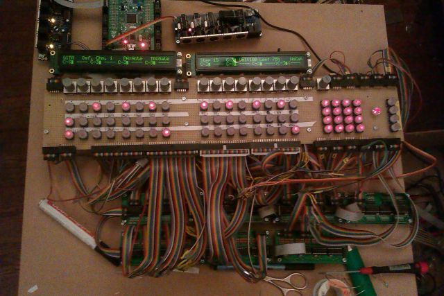
So, ungefähr Halbzeit:
☑ Coremodule gebaut, Software installiert
☑ LCDs angeschlossen
☑ 1. MIDI I/O gelötet und angeschlossen
☑ 4 DIN, 3 DOUT gelötet und angeschlossen
☑ 1 Midiquad gelötet und angeschlossen, ein PIC gebrannt.
☑ 69 Taster angeschlossen und verknüpft. (16 Encoder tasten parallel zur obersten Tastenreihe, ein Encoder extra).
☑ 69 Leds angeschlossen und verknüpft. (68 Leds in den Tastern, Tastenreihe, die Beat-LED extra).☠3 PICs brennen für das Midiquad-Modul
☠2. MIDI I/O löten und anschliessen
☠25-pin breakout port
☠AOUT NG löten und anschließen
☠Frontplatte lasern lassen
☠Gehäuse bauen
☠Kabelsalat reduzieren, einbauen, fertig.
Anmerkungen für bisher:
- Unter "MB Hardware Platform" sollte es eine Anleitung für das Quad-Modul geben. (Es reicht ja, wenn sie aus einem Link auf das "IIC MIDI Module" besteht)
- Das das MIOS Studio-Programm die nicht in der MBSEQ_HW.V4 verknüpften Taster mit Pinbelegung anzeigt, ist hilfreich. (Gibt es so etwas auch für die LEDs?)
- Die Undo, Clear, Copy, Paste-LEDs könnten auch nach dem Tasterdruck weiterleuchten, damit man (besoffen?) noch weiß, welche man zuletzt gedrückt hat.
-
ok, da bekomme ich gerade nichts hin. Also erst einmal andere Baustellen.
wenn man herausgefunden hat, dass man diese komischen ics noch programmieren muss, gehts...
wieder was gelernt.


Revised 25-pin breakout port
in MIDIbox SEQ
Posted
done.