
ksir
-
Posts
97 -
Joined
-
Last visited
-
Days Won
6
Content Type
Profiles
Forums
Blogs
Gallery
Posts posted by ksir
-
-
hello,
always about
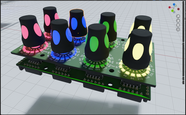
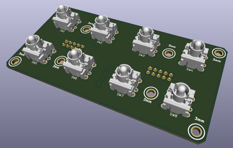
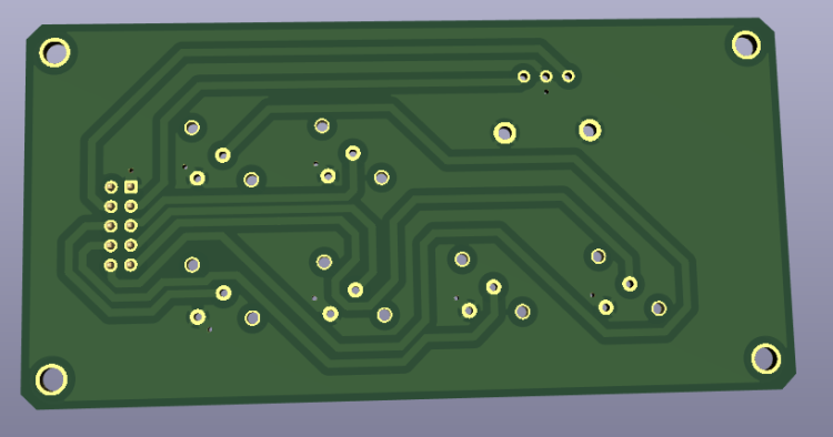
4x2 Enc RGB SW Led ring Rgb
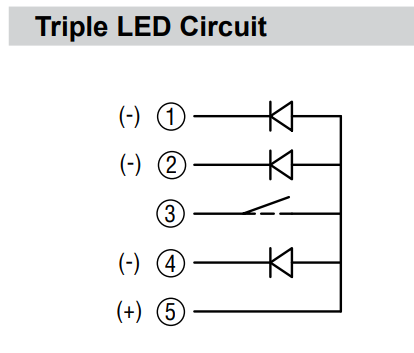
I abandoned the idea of a matrix for the rgb leds of the pel12t encoders. this simplifies the diagram.
for the common anode I read here: http://midibox.org/forums/topic/20713-how-to-connect-common-anode-rgb-leds/#comment-180389
just connect the cathodes to the DOUT pins.
595s can sink current, which means they "can supply ground/0V". Thus, the output is "reversed" for common anode parts. This can be specified in MB_NG. When the 595 output is high, the LED is off. When low, the LED is on.On the other hand I still do not know how to connect the switch of the pel12t encoders to the 74hc165.
normally a switch is connected between VS and D*
with its switches the contact is between VD and D*.Is there a way to solve this problem in a software way?
should I use a bc547 for example or other hardware solution?
another possible solution?https://drive.google.com/file/d/1kLTryPKwxlgYORO9NTeJ00XRjq4Sl2w4/view?usp=share_link
Thanks for your help
-
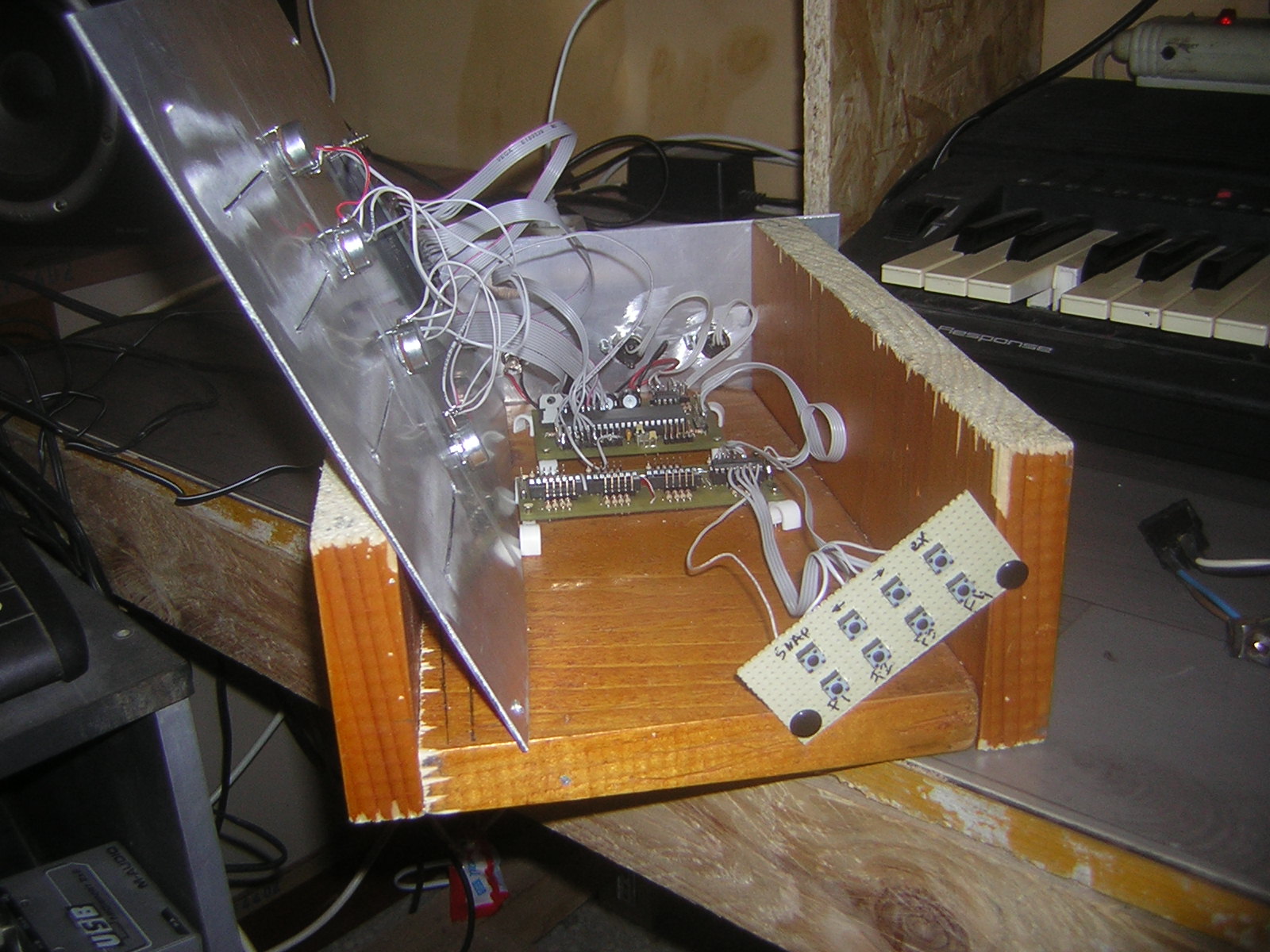
The module that gives me the most problem is the4x2 Enc RGB SW Led ring Rgb
https://drive.google.com/file/d/1kLTryPKwxlgYORO9NTeJ00XRjq4Sl2w4/view?usp=share_link
I'm trying to use Bourns RGB + Switch Pel12T Encoders
https://mou.sr/3zJilbU
https://www.mouser.fr/datasheet/2/54/PEL12T-777462.pdfBut the wiring diagram of the leds and switches of these encoders is a challenge for me:
the RGB LED matrix is also difficult.
Maybe it's not possible with a matrix because of the switch ?
Help and advice are always welcome.
and the lack of space on will also be a PCB challenge,
I may be forced to add a third sandwich panel. -
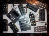
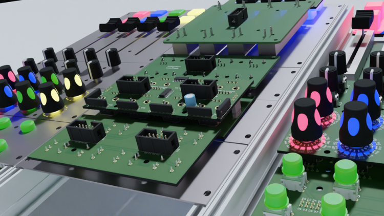
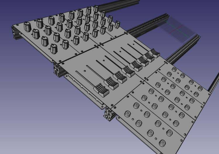
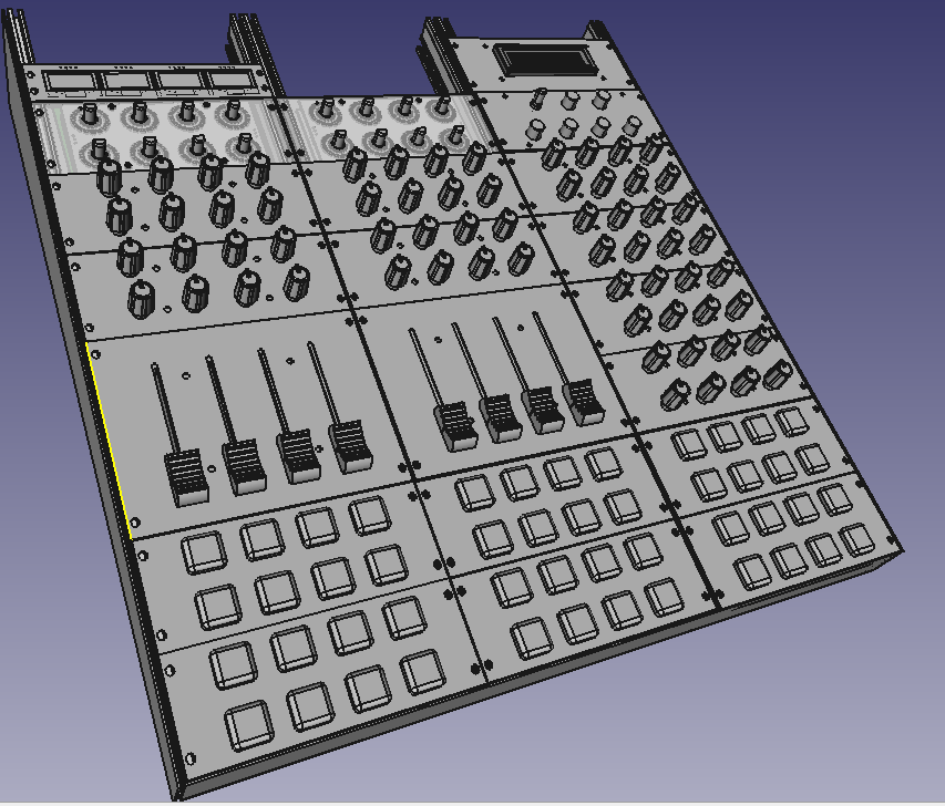
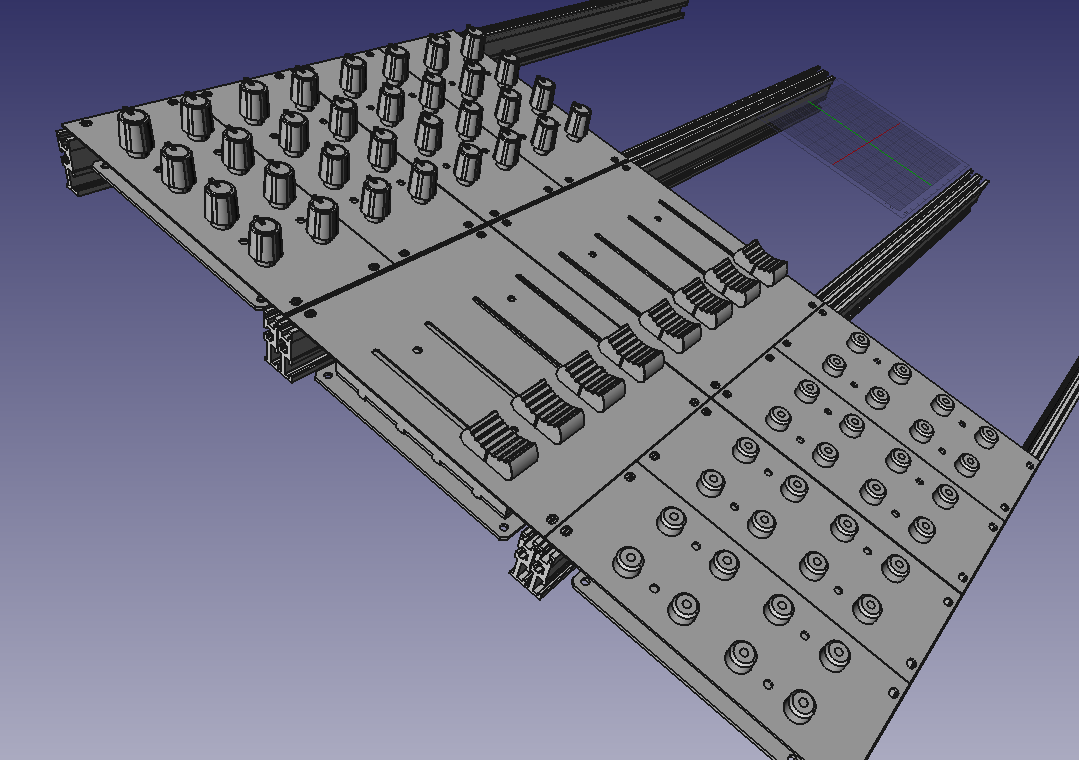
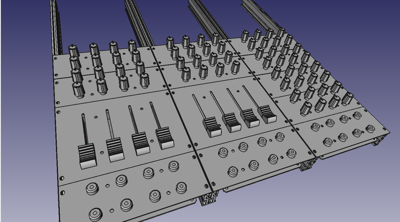
For fun, an overview of the modules already developed and under development
-
3 hours ago, Phatline said:
yes i can share it... will take a while... do you want to use it in a button-led-matrix "scalar" way?
Thanks
It's mostly to look at how you designed it. I would adapt it for the sparkfun 2x2 pads
i would like to use it with rgb leds
-
Good morning;
Thank you very much for your answers and your help which are very precious to me.I tried to correct my files according to your advice. (in the previously shared folder https://drive.google.com/drive/folders/1IZLVG2fVXstxGC9ZCWl0OCMjF7R1GEB3?usp=share_link) (I upgraded to version 7 of kicad).
I'm also trying to make a PCB with silicone buttons, (see in the TO_DO folder in the folder I shared)
how to create a footprint in kicad for silicone buttons, (like you did here: http://wiki.midibox.org/lib/exe/fetch.php?w=600&tok=c1a13e&media=phatline:blm16x16-pcb-3d-front.jpg)
Would you be willing to share your footprint?The files you will find in the TO_DO folder are in progress, full of errors and far from finished .... if you look at them, your advice is always welcome
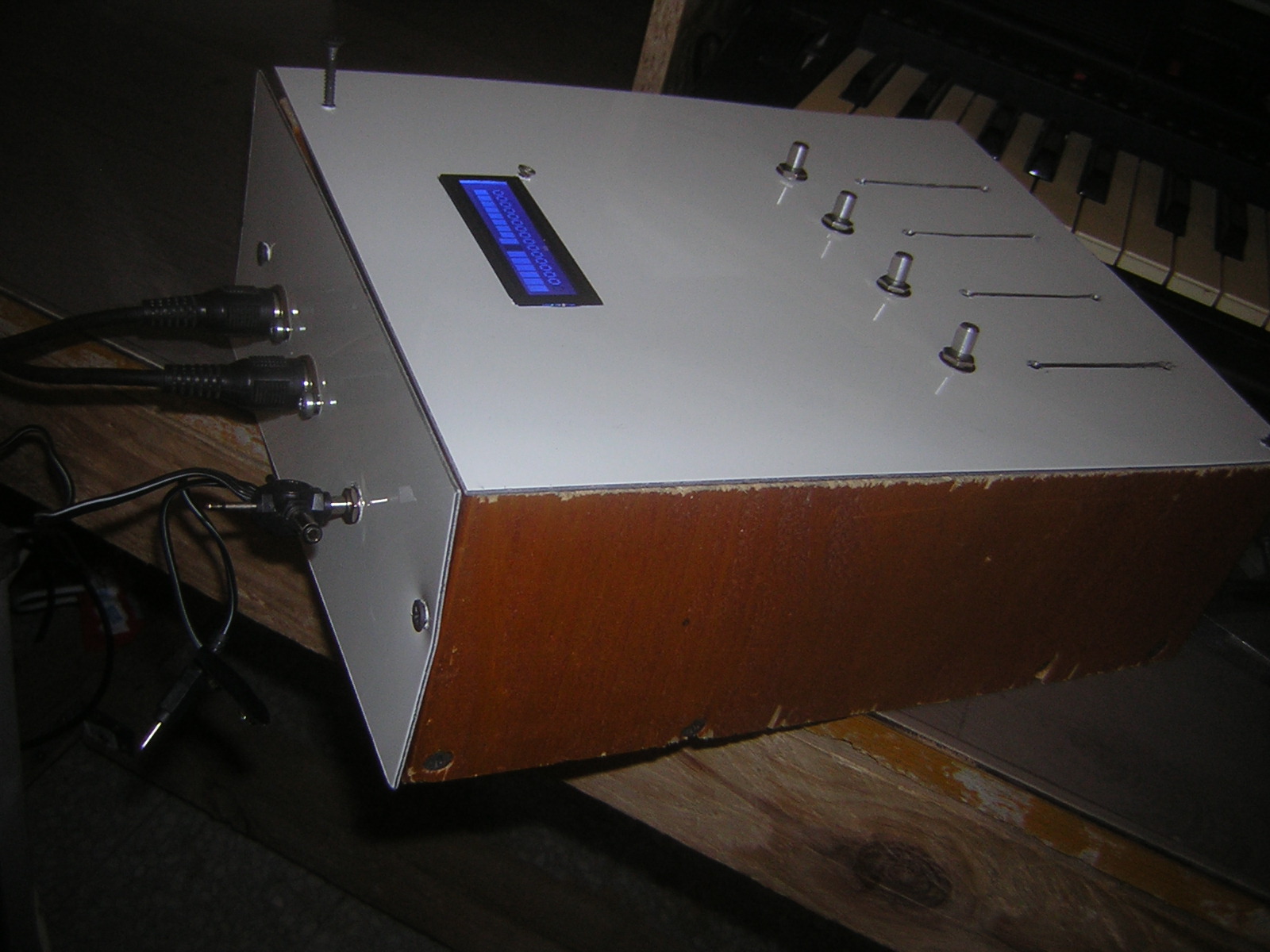
for fun, a vision of what my future controller could look like, disregard the screen at the top right, it could have a series of oled on the top

-
here is where I am at the moment:
https://drive.google.com/drive/folders/1IZLVG2fVXstxGC9ZCWl0OCMjF7R1GEB3?usp=share_link
i am looking for rgb leds
it is listed here:
http://www.ucapps.de/midibox_ng_manual_hw.html
you need an external power supply.how to handle this?
Thanks for your help
QuoteWith a MBHP_CORE_STM32F4 module it's possible to drive WS2812 based RGB LEDs (usually used for LED strips) with 3x8bit resolution. The data input has to be connected to J4B.SC, ground to J4B.VS and +5V to an external PSU (required, since each RGB LED can consume up to 20 mA!)
Up to 64 RGB LEDs can be driven by the core. More could be enabled if desired by increasing the number with '#define WS2812_NUM_LEDS <number>' in the mios32_config.h file, but note that each LED will consume 48 bytes and therefore the RAM limit of the STM32F4 could be reached quickly! However, 128 LEDs are working ok so far, but this could change than more firmware features are added in future. -
thank you for your reply
Quotesuggestions? Maybe use the Eurorack format, so it can also be used outside your box?
I'm working on it :

I noticed you don't like the MEC buttons, I'm looking at the alternatives. maybe cherry switches, I need to find some nice caps (any suggestions?)
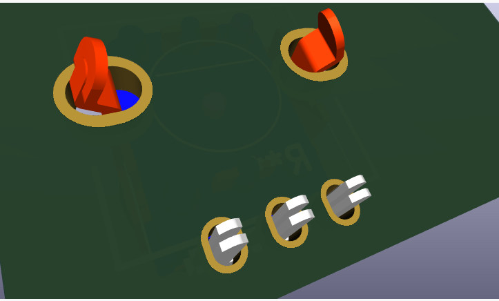
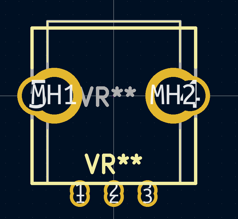
I want to merge 2 footprints for the potentiometers:
(so that I can use different potentiometers)
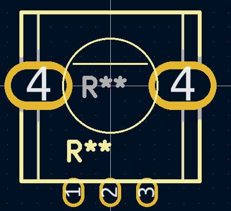
Is this a bad idea?
should I connect pads 4 to the -?
thank you for your help
-
Hello,
I am currently thinking about a version 2 of my modulbox circuits
V1:
the objectives are:
Have the circuits manufactured by a professional (for example: https://jlcpcb.com/).
Have the fronts made by a professional.
-Be able to more easily share the circuits created with the communityThe design rules remain the same:
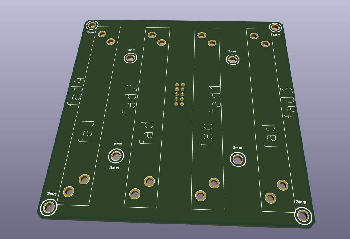
circuits of 50 x 100 mm or 100 x 100 mm max
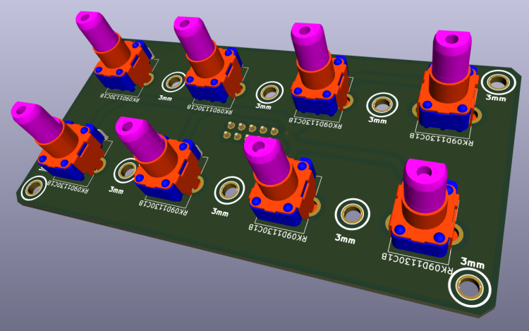
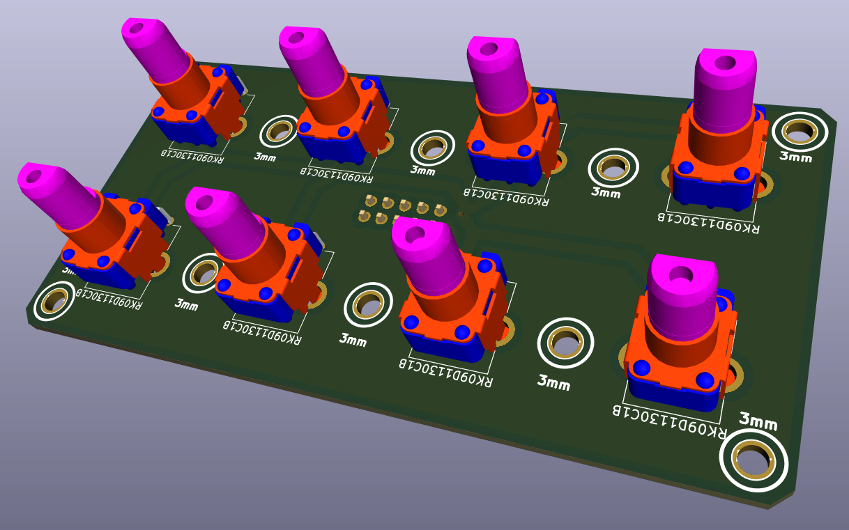
For the potentiometers I used: RK09L1140A2U ( https://www.mouser.fr/ProductDetail/Alps-Alpine/RK09L1140A2U?qs=6EGMNY9ZYDShe59Bf8g9AA%3D%3D )
paid 0.70 euros each at the time, they cost 2.80 euros today,
I'm thinking of replacing them with RK09D1130C1B ( https://www.mouser.fr/ProductDetail/688-RK09D1130C1B )
they are cheaper.Do you recommend another model / brand?
I'm thinking of trying to make a footprint that accepts several kinds of potentiometers. it's possible ? does it already exist? (I work with kicad)
(for caps: https://www.mouser.fr/ProductDetail/Eagle-Plastic-Devices/450-4760?qs=J4wJDGtbthoFgTzq4MR8dw%3D%3D)
For the faders I used: RA6020F-10-15F2-B10K ( https://www.mouser.fr/ProductDetail/Alpha-Taiwan/RA6020F-10-15F2-B10K?qs=6TczTpqoAMVgxoAgFDSJ8A%3D%3D )
It may not be the best choice.Do you recommend another model / brand?

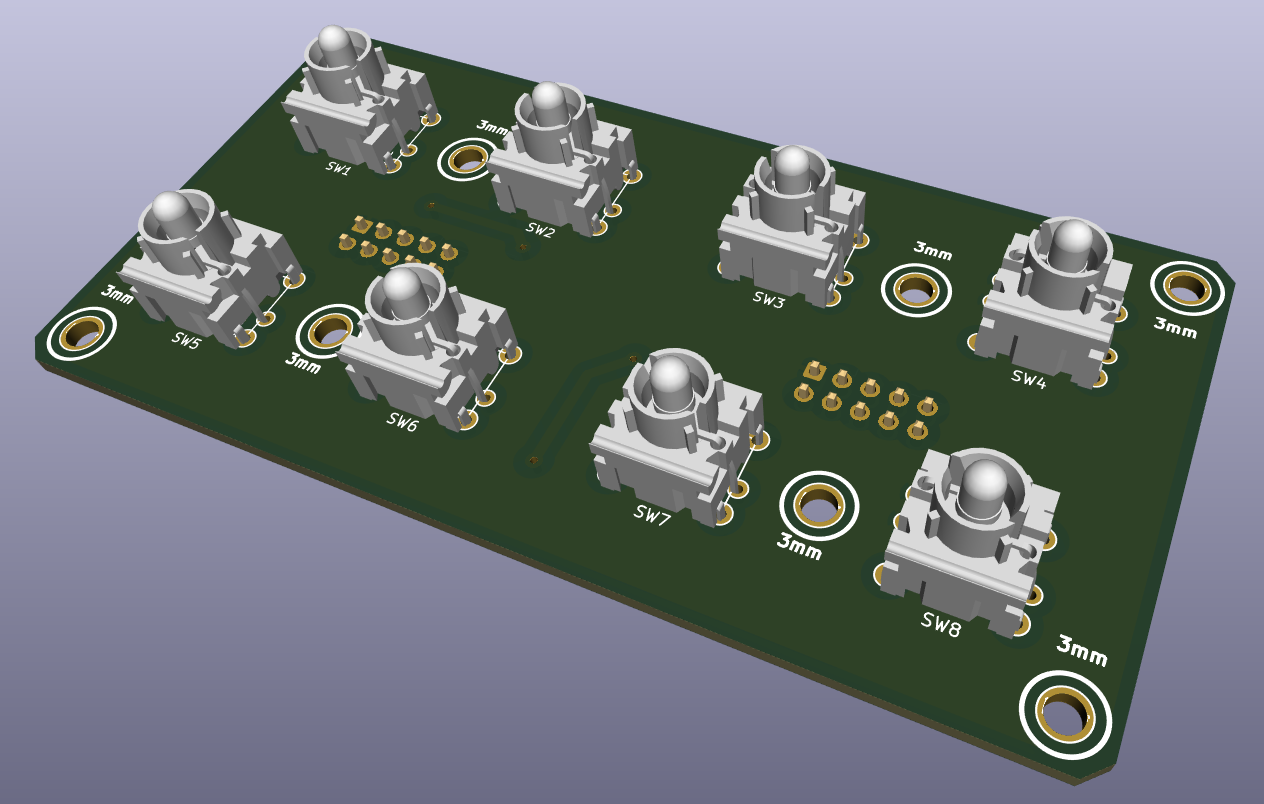
For the push buttons I used: MEC 3FTH9 https://www.reichelt.de/fr/fr/bouton-multimec-sans-clairage-connecteur-circuit-imprim--taster-3fth9-p156904.html?GROUPID= 7587&SHOW=1&OFFSET=16&&r=1
Do you recommend another model / brand?
It also remains to update the standard control surface:
I'm also thinking about possibly making a 4 x 2 sparkfun pads with RGB led ( https://www.sparkfun.com/products/7836 )
I still have a lot of work.
Anyone interested in this project? People who would like to help me or simply control my work?
or do you have any advice or suggestions?
Thanks
-
-
-
Très cool! Tu as utilisé un Core 8 ou 32 bit?
heu, j'ai utiliser un lpc17 ..
Salut Ksir,Connais tu les modules de chez e-licktronic, il ressemble étrangement à tes modules de 8 potentiomètres

oui j'avais déjà vu ces modules
mais je me suis inspirer de livid
-
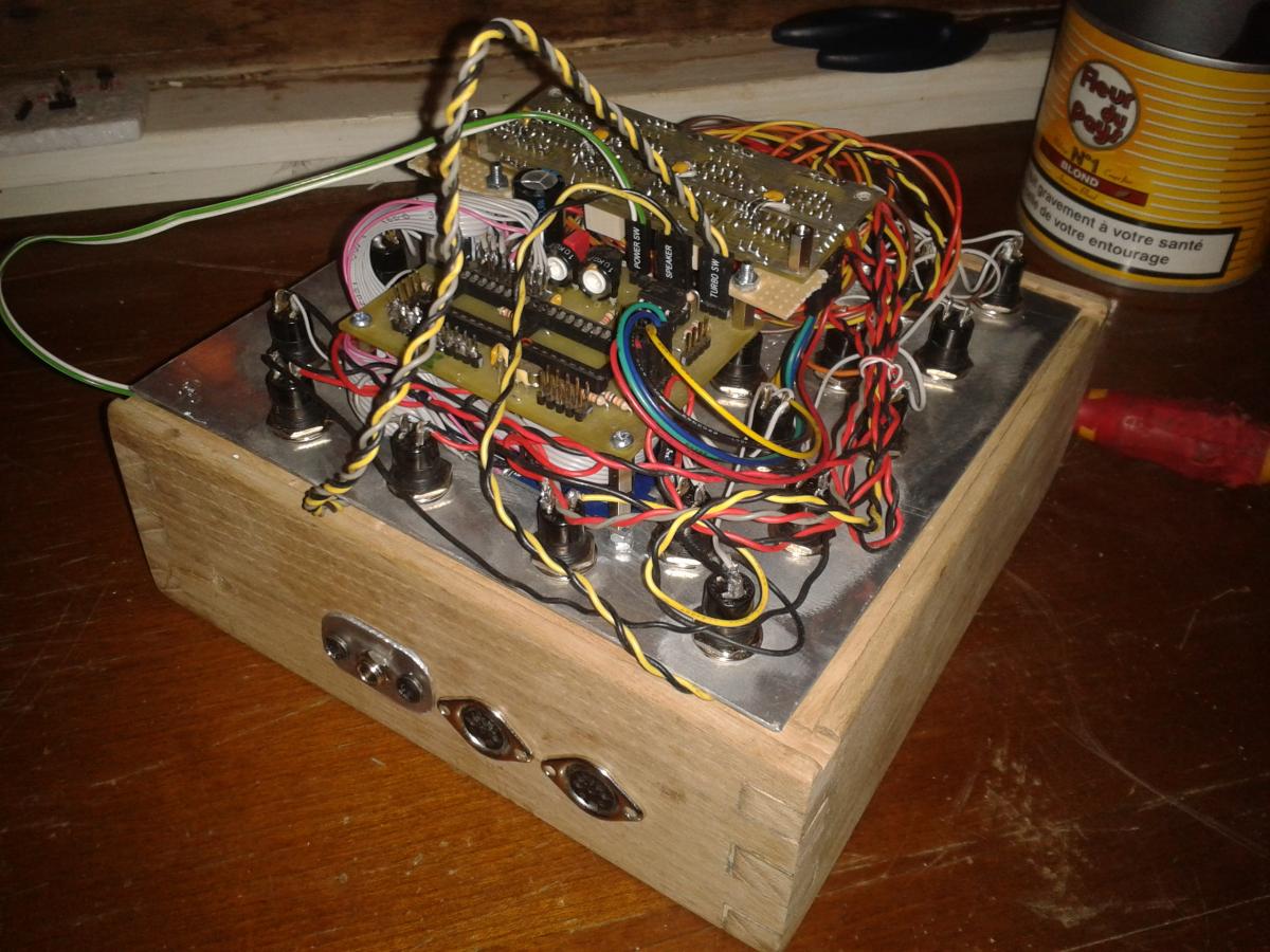
bonjour a tous,
je viens de finir ma midi box ng ,
inspirer par livid élément , j'ai voulut reprendre le même principe d’élément modulable.

il me reste1 ou 2 petit bug
un petit peu de programation
a huiler les flancs en bois ..
-
merci , cela semble fonctionner
-
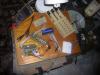
bonjour,
je suis entreint de concevoir une midi box baser sur des modules .
sur la 2ieme photo on voit les ecrous touche le plan de masse que j'ai relier a vss.
du coup toute ma boite en alu sera relier a vss ..
vous l'avez compris je ne comprend pas vraiment vss et masse .
pourriez vous m'éclaircir a se sujet, et me dire si toute ma boite ( boitier en alu) peut etre relier a vss.
merci
-
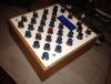
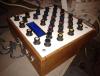
salut ..
j'ai enfin fini ma box...
je vous fait par des dernieres photos ..

-
j'ai finalement commander chez lextronic
32 boutons comme ceux la : http://www.lextronic.fr/P5354-r1821bb125.html

tout fonctionne bien a première vu , reste a comprendre comment fonctionne la bête , lui faire une belle boite en bois ,
j'ai aussi commander un module dout que je brancherez bientôt.
j'ai bien envie de rajouter 28 potard ( il y en a deja 4 ) mais dans se cas je devrait commander un ain ..
a+
-
j'ai relié les entrées analogique a la masse sa a résolut mon problème..
les boutons que j'ai commander sont vraiment trop petit :/
je vais en recommander si vous pouviez m'en conseiller .
pour l'instant j'ai trouver sa :

http://fr.farnell.com/jsp/search/productdetail.jsp?sku=1634621
j’aimerais aussi trouver des connecteur au lieux de souder toutes les pattes

http://fr.farnell.com/jsp/search/productdetail.jsp?sku=1593506
c'est les bon connecteurs ? il me faut aussi une pince a sertir avec ..? il n'y a pas d'autre modèle plus simple ? la encore si vous aviez quelques conseil ..
a bientôt.

-
j'ai trouvé sa traduction google tradution:
Si vous téléchargez une application qui réagit sur ​​les lignes d'entrée analogique du PIC ou un module AIN (par exemple MIDIbox64 ou MIDIbox LC ), le noyau sera propably envoyer beaucoup de hasard des événements MIDI si longtemps sans pots / faders ou d'autres sources de tension sont connectés aux entrées analogiques - donc toutes les entrées analogiques unusued devrait toujours être serrées au sol.
je pense que mon problème vient de la ..
-
j'ai essayer d'installer l'appli mb64 avec seulement 8 bouton de brancher,
mais la encore un problème , une fois charger l'appli la mb a un comportement incoherent comme si j’appuyais sur les boutons..
j'ai donc débrancher le din, il n'y a donc plus que le core et le lcd de brancher,
j'ai re charger l'appli mb64 et la encor sa fait comme si j’appuyais sur les boutons, je me retrouve dans les menus et sa change en permanence a l’écran. dans mios studio je reçoit en permanence des données midi ...

-
youpi sa marche :
READY !!
il suffisait d'installer mios 1.9 .. !
-
j'ai essayer de revoir quelques soudures ... ( après avoir enlever le pic )
après avoir remit le pic retour sur mios studio et la c'est encore pire mios studio ne détecte plus ma mb.. :angry: grrr
du coup je teste les tensions ; http://www.ucapps.de/howtodebug/mbhp_core_extract_measuring_vdd.gif
la il y a la moitié des tensions qui sont bonnes :
de j2 vs vers :
IC1, 1 mclr# 5.04 v
IC1, 11 vdd 5.04
IC1, 20 rd1 0 ( mais si je prend la tension entre j2 vd et ic1 20 j'obtient -5.04v )
IC1, 32 vdd 5.04
IC1, 26 rx 0.03
IC1, 25 tx 5.04
IC2, 8 5.04
j12 m- 0
le probleme serait il une mauvaise soudure ou pont entre 2 piste proches que j'aurai relier par inadvertance..?
edit :
pb de tension resolu et de reconnaissance midi par mios studio resolu aussi.
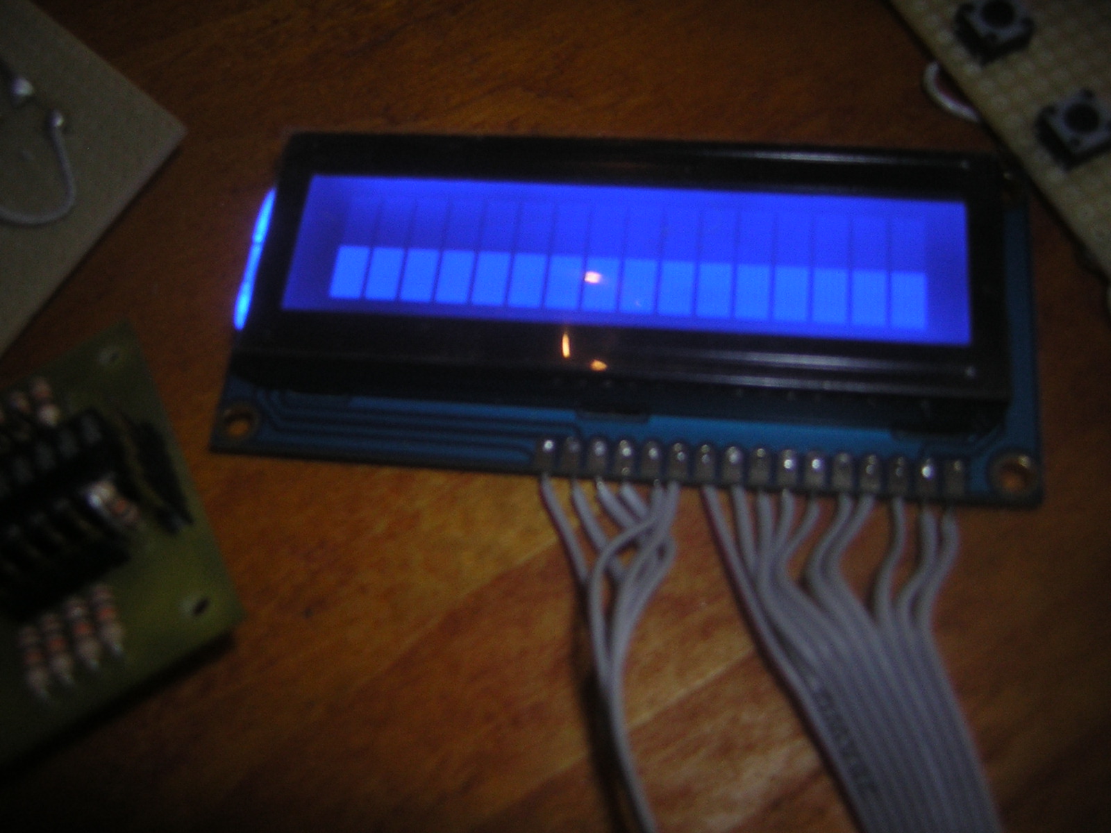
reste le pb de l'ecran ... tjr une ligne de carré ..
doit-je installer mios_v1_9g.zip ? ou juste l'apli mb 64 ?
-
j'ai essayer de régler le contraste et la luminosité ...
j'ai toujours une ligne de carré ..
a la fin de l'upload de midibox64.hex
ma mb ne redémarre pas il me semble qu'elle devrait redémarrer.
j'ai commander mon pic chez mike, il doit déjà être flasher ? doit-je installer mios_v1_9g.zip ?
( mon alim ne fait 300mA sa peut venir de la ? )
encore merci pour votre aide .
-
je ne sait pas si c'est la ligne inférieur ou supérieur ( je ne sait pas dans quel sens va l’écran ..) mais il y a une des 2 lignes qui est remplie..
mios studio m'a dit :
Reading setup_midibox64.hex
Trying to contact the core...
setup_midibox64.hex contains 18060 bytes (71 blocks).
Range 0x00003000-0x00006fff (16384 bytes) - PIC Flash
Range 0x00007600-0x00007bff (1536 bytes) - PIC Flash
Range 0x00f00000-0x00f000ff (256 bytes) - PIC EEPROM
Upload of 18176 bytes completed after 14.52s (1.22 kb/s)
Operating System: MIOS8
Board: MBHP_CORE or similar
Core Family: PIC18F
Bootloader is up & running!
-
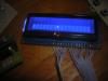
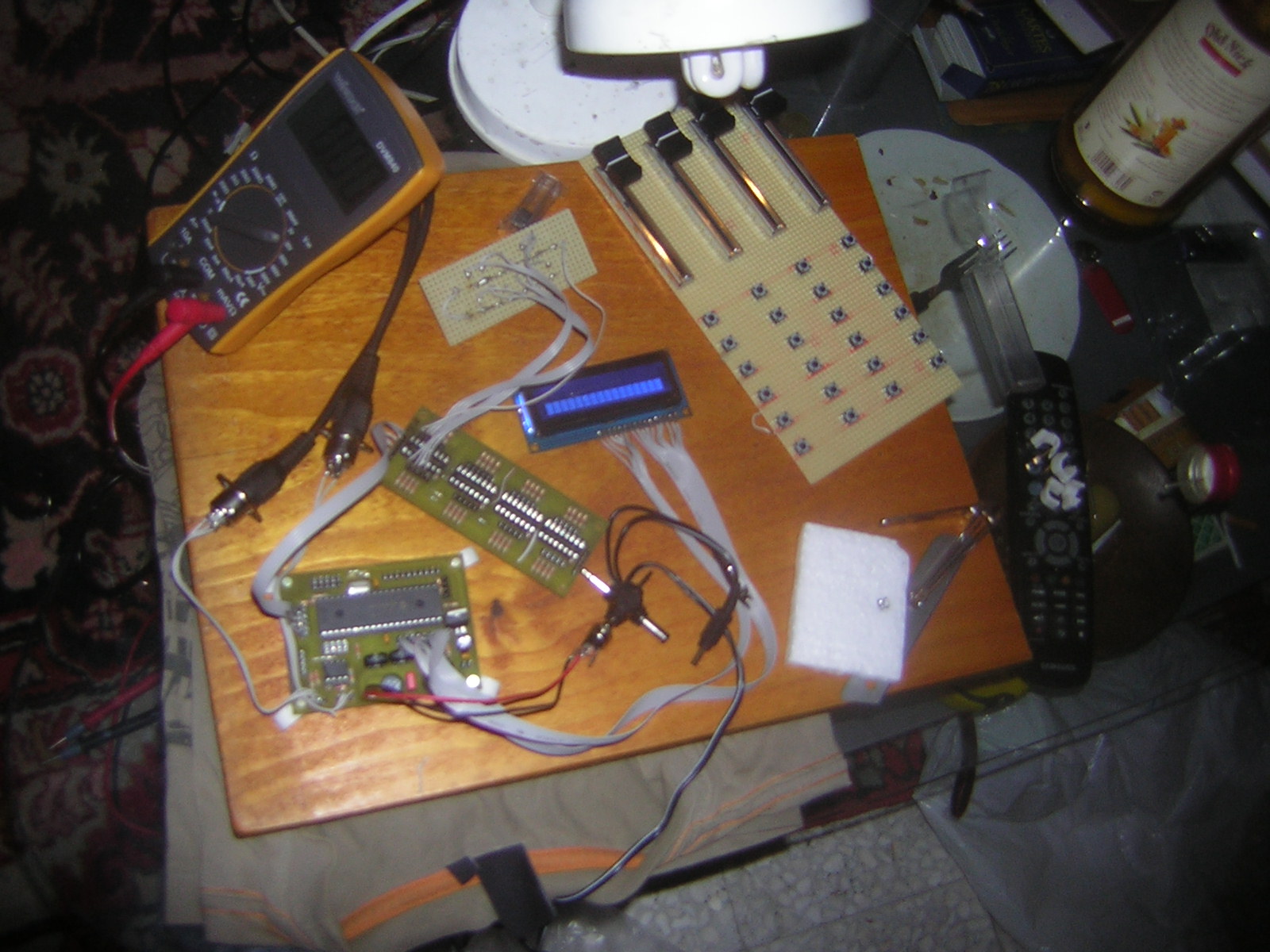
premier test et premier problème :sad: :
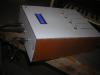
j'ai fini le core
uploader l’application midi box 64
une photo si joint pour vous montrer ce qu’affiche mon écran lcd..
si vous avez une idée d’où vient mon problème .
je debugerai demain : http://ucapps.de/howto_debug_midi.html
merci et big up !


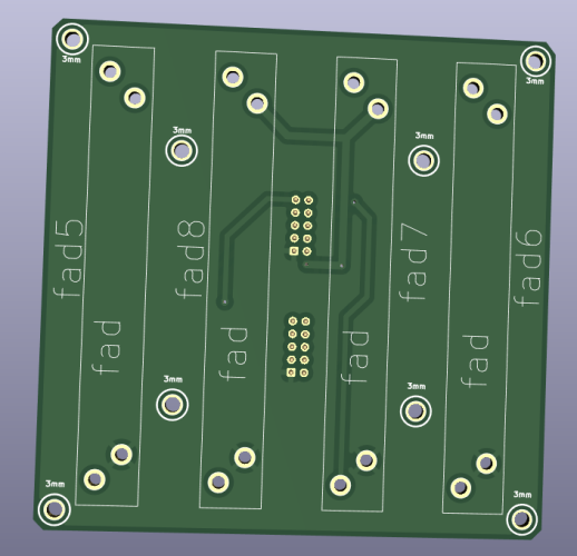
Modul Box NG V2
in MIDIbox NG
Posted · Edited by ksir
Thank you for your involvement in my project.
After studying novski's projects https://github.com/novski/Midibox/tree/master/VLR-8Enc
It uses an uln2803 for the switches.
I reproduced its layout, but I don't really understand how Darlington transistor arrays work.
https://drive.google.com/file/d/1EW-IxclCJ1_cOeau-bTUnaOuSZ5eGdsN/view?usp=share_link
I will study the solution you propose with 74HC1G14.
you are right and will try to take your remarks into account.
although I don't have a solution yet.
the alps caps are pretty and I couldn't find a smaller equivalent.
thank you again for your involvement
The encoders and silicon pad modules are far from finished.
the other modules are almost ok for me, I should check them again.
maybe you can watch this if you want.
but if you have little time, I would not like to waste it and keep the time you can give me to really check the modules that I think I have completely finished