Lamouette
-
Posts
369 -
Joined
-
Last visited
-
Days Won
4
Content Type
Profiles
Forums
Blogs
Gallery
Everything posted by Lamouette
-
Thanks a lot Hawkeye, you have been a really great helper ! Now i have to work the case, but that should be easier for me. I will keep my thread updated, it could be a great help for someone like me who strart from nothing ! And finnaly it is funny as the first pcb i ever solderd (a DOUT), is the last i added to my build ! it was fun to check my first solder :)
-
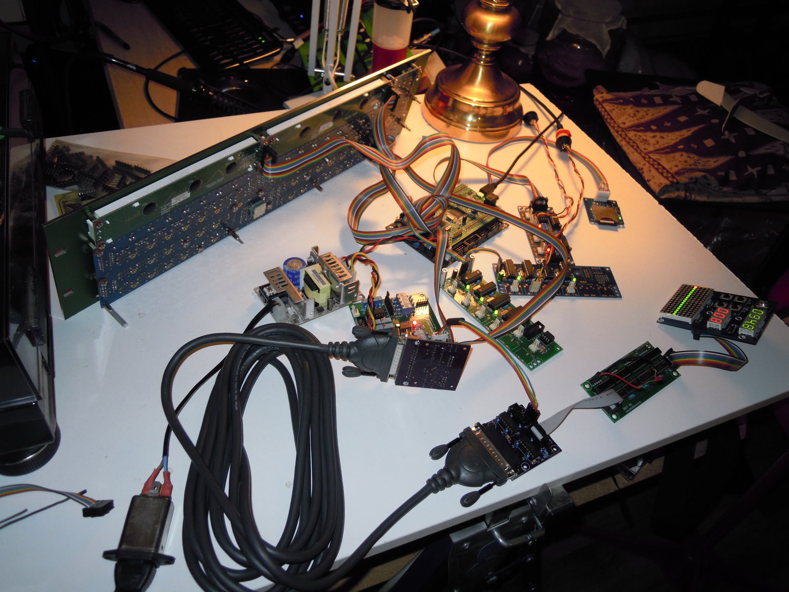
Hell yeah, after huge reading, IT WORKS !!!!!!!!!!!!!! So after a long story, i just finished the electronics, a picture is needed to immortalise the moment, really, a great moment !

-

New Topics in MBHP>Basics section of the wiki
Lamouette replied to Psykhaze's topic in MIDIbox Documentation Project
This is really helpfull, thanks for doing this ! -
I trided to modifiy the shift register number, but it is not working : As the TPD in normal connection, is connected to 5 6 7 8 9 10, i suppose the shift register 1 2 3 4 already used by the wilba panel. (1&2 by wilba BLM, and 3&4 by BPM digit) I tried to put the TPD at the end of the chain, to avoid problems, so : Original config : # See also http://www.midibox.org/dokuwiki/doku.php?id=tpd_pcb ################################################## # set to 1 or 2 to enable the relative track position display # 0: TPD disabled # 1: TPD enabled - columns are cathodes, rows are anodes # 2: TPD enabled - columns are anodes, rows are cathodes TPD_ENABLED 2 # define the DOUT shift register to which the columns are connected (0=disabled) TPD_COLUMNS_SR_L 10 # for a 16x16 TPD: define the SR to which the right columns are connected (0=disabled, use only 8x8 TPD) TPD_COLUMNS_SR_R 7 # define the DOUT shift register to which the green LED rows are connected (0=disabled) TPD_ROWS_SR_GREEN_L 8 # define the DOUT shift register to which the right green LED rows are connected (0=disabled, use only 8x8 TPD) TPD_ROWS_SR_GREEN_R 5 # define the DOUT shift register to which the red LED rows are connected (0=disabled) TPD_ROWS_SR_RED_L 9 # define the DOUT shift register to which the right red LED rows are connected (0=disabled, use only 8x8 TPD) TPD_ROWS_SR_RED_R 6 ################################################## # CV and Gate/Trigger/Sync Setup ################################################## # AOUT interface now selected in CV Configuration Menu and stored in MBSEQ_GC.V4 file # please scroll through the menu to find this page! # the 8 CV gates can be assigned to a shift register (0=off, 1-32: number of shift register): # - 1st CV Gate available at DOUT SR output D7 # - 2nd CV Gate available at DOUT SR output D6 # - 3rd CV Gate available at DOUT SR output D5 # - ... # - 8th CV Gate available at DOUT SR output D0 CV_GATE_SR1 0 # and DIN Clock Outputs can be assigned to a shift register as well (0=off, 1-32: number of shift register): # D7..D0 will output individual clock or start/stop signals which can be configured in the CV configuration page CLK_SR 0 # additional gate triggers are available on common digital output pins of the # DOUT shift register chain - they are assigned to AOUT channel #16 (Note C-1, C#1, D-1, ...) # define the shift registers which should be used here (each provides 8 gates) # Note that SRs assigned to this function cannot be used as LED outputs (exclusive function) # Allowed values: 1-32, 0 disables the function, all other values invalid and not allowed DOUT_GATE_SR1 0 DOUT_GATE_SR2 0 DOUT_GATE_SR3 0 DOUT_GATE_SR4 0 DOUT_GATE_SR5 0 DOUT_GATE_SR6 0 DOUT_GATE_SR7 0 DOUT_GATE_SR8 0 # if set to 1, the additional DOUT "gates" will send 1mS pulses # useful for analog drums DOUT_1MS_TRIGGER 0 Modified config : # set to 1 or 2 to enable the relative track position display # 0: TPD disabled # 1: TPD enabled - columns are cathodes, rows are anodes # 2: TPD enabled - columns are anodes, rows are cathodes TPD_ENABLED 2 # define the DOUT shift register to which the columns are connected (0=disabled) TPD_COLUMNS_SR_L 14 # for a 16x16 TPD: define the SR to which the right columns are connected (0=disabled, use only 8x8 TPD) TPD_COLUMNS_SR_R 11 # define the DOUT shift register to which the green LED rows are connected (0=disabled) TPD_ROWS_SR_GREEN_L 12 # define the DOUT shift register to which the right green LED rows are connected (0=disabled, use only 8x8 TPD) TPD_ROWS_SR_GREEN_R 9 # define the DOUT shift register to which the red LED rows are connected (0=disabled) TPD_ROWS_SR_RED_L 13 # define the DOUT shift register to which the right red LED rows are connected (0=disabled, use only 8x8 TPD) TPD_ROWS_SR_RED_R 10 ################################################## # CV and Gate/Trigger/Sync Setup ################################################## # AOUT interface now selected in CV Configuration Menu and stored in MBSEQ_GC.V4 file # please scroll through the menu to find this page! # the 8 CV gates can be assigned to a shift register (0=off, 1-32: number of shift register): # - 1st CV Gate available at DOUT SR output D7 # - 2nd CV Gate available at DOUT SR output D6 # - 3rd CV Gate available at DOUT SR output D5 # - ... # - 8th CV Gate available at DOUT SR output D0 CV_GATE_SR1 5 # and DIN Clock Outputs can be assigned to a shift register as well (0=off, 1-32: number of shift register): # D7..D0 will output individual clock or start/stop signals which can be configured in the CV configuration page CLK_SR 6 # additional gate triggers are available on common digital output pins of the # DOUT shift register chain - they are assigned to AOUT channel #16 (Note C-1, C#1, D-1, ...) # define the shift registers which should be used here (each provides 8 gates) # Note that SRs assigned to this function cannot be used as LED outputs (exclusive function) # Allowed values: 1-32, 0 disables the function, all other values invalid and not allowed DOUT_GATE_SR1 7 DOUT_GATE_SR2 8 DOUT_GATE_SR3 0 DOUT_GATE_SR4 0 DOUT_GATE_SR5 0 DOUT_GATE_SR6 0 DOUT_GATE_SR7 0 DOUT_GATE_SR8 0 # if set to 1, the additional DOUT "gates" will send 1mS pulses # useful for analog drums DOUT_1MS_TRIGGER 0 But i got nothing on the TPD... Any thoughts ? The TPD have 9 Shift register but i can only see 6 assigned on the MBSEQ_HW.V4
-
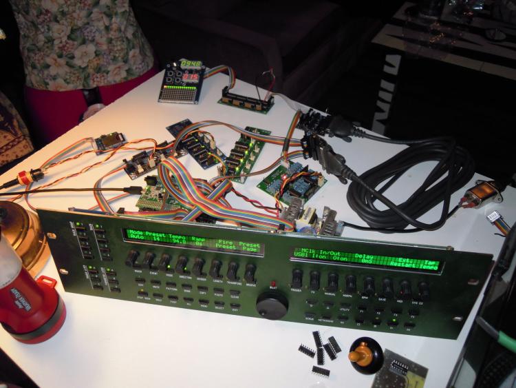
Hi there, some news on my side ! I have now installed a proper ubuntu on a disk partition, and could do some make files without any problems, i really enjoy this OS, so well done on your side guyz For my SEQV4 : SEQ is working 2 Quad-IIC working Line driver working Aout_NG working TPD Working So it is a long road i did, and i am close to the end of the project ! Thanks a lot for you awesome help, and you really friendly behavior ! I learned a lot about different things, i am now a proud soldereing guy, but i know i have lack of electronic and programming knowledge ! Also, speaking in english everytimes here helped me a lot to improve my language ! But the road is not ended yet ! I want to use the line driver to make a separate eurorack module, which would include, a TPD, the AOUT_NG for the cv, and 1 or 2 DOUT for the gate/trigger/clocks. Here is my question, i read about problem with the TPD not at the end of the DOUT chain. It is not a problem to connect 1 or 2 DOUT on J2 of the LINE DRIVER RECEIVER, and plug the TPD at his end ? (if i assign the correct Shift rehister number) ?
-
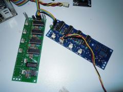
You need to get the PIC16F88 for the 2nd quad IIC burned with this firmware : http://midibox.org/forums/applications/core/interface/file/attachment.php?id=11978 And you will have to change some line on your midibox firmware mios32_config.h #define MIOS32_USB_MIDI_NUM_PORTS 8 and you connect both boards in series, like this : Have fun !
-
From the album: Lamouette - Midibox
-
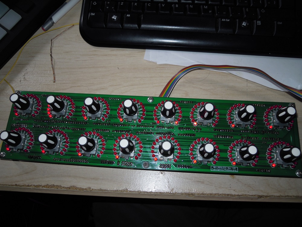
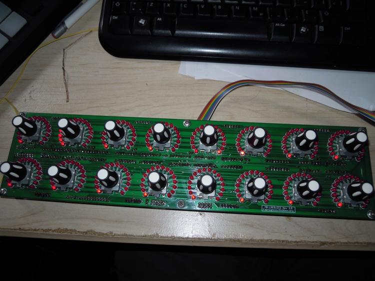
Hello there, I have one MB-LRE8x2CS PCB version 2.5 to give. all the ledrings works as expected but the number 9, i tried to troubleshoot it, but i cannot put the finger on what's wrong with it. i will keep the ICs, and knobs. 2 Condition : 1) i just want to be sure i cannot found a replacement one so i will not give it once i have another one. 2)You pay the shipping, i live in Canada, so north america will be cheaper for you !
-
MB-LRE8x2CS need your help for something
Lamouette replied to Lamouette's topic in MIDIbox User Projects
yes, i had understoood this, thanks for the explain. and yes, i am pretty sure this is a scratch problem with the soldermask.... Evrytime the 16th of the faulting ledring is lit.i removed the coper all around, but it is still the same if i turn the encoder until the 16led normally lit, all the other led have a really little brightness, once i pass the 15th , the 16th stop working and no other one is lighting -
MB-LRE8x2CS need your help for something
Lamouette replied to Lamouette's topic in MIDIbox User Projects
ok, if i understand correctly, and after continuity check, when the 16th led of the ledrings 11/12/13/14/15 are lighting they are creating a short on the led 16 on the ledring 9 -
MB-LRE8x2CS need your help for something
Lamouette replied to Lamouette's topic in MIDIbox User Projects
and same problem... i don't understand... -
MB-LRE8x2CS need your help for something
Lamouette replied to Lamouette's topic in MIDIbox User Projects
oh, no i forgot it, but anyway, all should have had the same state. i am redoing all the solder point of the ICs. i keep you updated ! Thanks ! -
MB-LRE8x2CS need your help for something
Lamouette replied to Lamouette's topic in MIDIbox User Projects
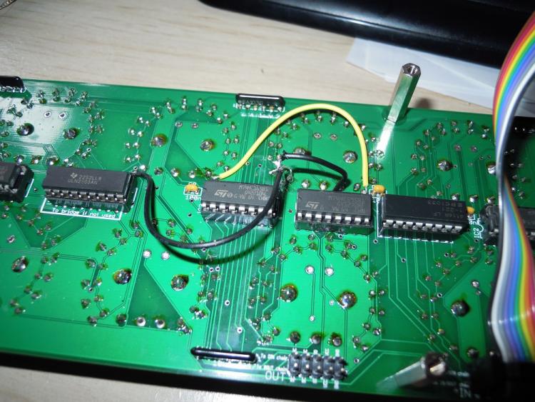
i removed the ULN2803, i used direct linking, now : all the 16th led of the ledrings 11/12/13/14/15 are lighting in continue. and if i move any encoder, i can see all the led lighting really low all around the led ring. -
MB-LRE8x2CS need your help for something
Lamouette replied to Lamouette's topic in MIDIbox User Projects
i am using the uln2803 -
MB-LRE8x2CS need your help for something
Lamouette replied to Lamouette's topic in MIDIbox User Projects
Yep, it is what i did, i just killed the pad, the remove the short, no now, the led is working, and i have no more the problem on seeing a bit of the other ledring move on this led ring. But (Yep, there is always an anoying ''but'' to explain, the not working led was the last one of the led ring 9 (the number 144) now, when i turn the encoder all the led are lighting, but for the ledring 11 12 13 14 15 16, all the 15 first led are lighning correcly, but the last one, is less uliminated, and so the precedently not working light is also lit, and for each one of the lasts led lightning, it is more lit (i an nore sure it is really clear) -
MB-LRE8x2CS need your help for something
Lamouette replied to Lamouette's topic in MIDIbox User Projects
yes, but as the link is between the 2 led pads, i don't expect it to work corectly, i seen that the pcb designer (fairlightIII) was not anymore on the forum, so i think it is dead to as k him the correct layout of the pcb... -
MB-LRE8x2CS need your help for something
Lamouette replied to Lamouette's topic in MIDIbox User Projects
i just swap the ic, but nothing changed, i really think it is because of the short on the led, but i cannot find any point, and the layout of the project page don't fit with my PCB, so it is hard to follow the trace. http://jeromebo.free.fr/Wiki/Layout.pdf -
Hi there, it is me again ! I am on the end of my 32 encoders board, everything works as expected but there is just one thing, one stupid led which not work ! I explain : When i turn an other encoder i can see a little bit of little across the ledring with the dead led. for each led lit, all the other reduce their brightness. it is the only one ring which do this, all the other one works as expected ! I checked the continuity between the 2 legs of the legs, and effectively they are linked together. so the led don't work, i checked all around, cannot find any place with a link between 2 solder, any other place i could chec or maybe it is another component dead ? i already unsoldered 3 times, i started to scratch some part on the pcb, because i thought the problem was on the pcb itself..... Any help ? Thanks ! Lamouette
-
I reinstalled a new VM on 32Bit, and could install libgmp3-dev , maybe it was the problem ! I have to format my computer, so i will install a proper linux session, i will reinstall all, like that i will have a way to ''make'' more ! :) Thanks again !
-
IT IS WORKING ! An enormous thanks to all people who helped me ! You are awesome !
-
Thanks Keeze, it is encouraging ! When i try sudo aptitude install lib32gmp3-dev i get everytime : Couldn't find any package whose name or description matched "lib32gmp3-dev" Couldn't find any package whose name or description matched "lib32gmp3-dev" No packages will be installed, upgraded, or removed. 0 packages upgraded, 0 newly installed, 0 to remove and 78 not upgraded. Need to get 0 B of archives. After unpacking 0 B will be used.
-
Ok, thanks again for all the time you take to help me, it is a hard case here :) So i could extract the .tar with your command lines But : When i do : make lamouette@lamouette-VirtualBox:~/midibox/mios32/trunk/apps/sequencers/midibox_seq_v4$ make rm -f project.hex Creating object file for app.c make: arm-none-eabi-gcc: Command not found make: *** [project_build/core/app.o] Error 127 same error. When i do : make --trace make: unrecognized option '--trace' When i do : set | grep PATH lamouette@lamouette-VirtualBox:~/midibox/mios32/trunk/apps/sequencers/midibox_seq_v4$ set | grep PATH COMPIZ_BIN_PATH=/usr/bin/ DEFAULTS_PATH=/usr/share/gconf/ubuntu.default.path MANDATORY_PATH=/usr/share/gconf/ubuntu.mandatory.path MIOS32_BIN_PATH=/home/lamouette/midibox/mios32/trunk/bin MIOS32_PATH=/home/lamouette/midibox/mios32/trunk PATH=/usr/local/sbin:/usr/local/bin:/usr/sbin:/usr/bin:/sbin:/bin:/usr/games:/usr/local/games:/usr/local/gcc-arm-none-eabi-4_7-2013q3/bin XDG_SEAT_PATH=/org/freedesktop/DisplayManager/Seat0 XDG_SESSION_PATH=/org/freedesktop/DisplayManager/Session0 local cmd PATH=$PATH:/sbin; if [[ -z "${CDPATH:-}" || "$cur" == ?(.)?(.)/* ]]; then for i in ${CDPATH//:/' PATH=$PATH:/usr/sbin:/sbin:/usr/local/sbin type $1 &> /dev/null COMPREPLY=($( compgen -W "$( PATH="$PATH:/sbin" lsmod | awk '{if (NR != 1) print $1}' )" -- "$1" )) local PATH=$PATH:/sbin; local PATH="$PATH:/sbin:/usr/sbin"; COMPREPLY+=($( compgen -W "$( PATH="$PATH:/sbin" lspci -n | awk '{print $3}')" -- "$cur" )) local PATH=$PATH:/sbin:/usr/sbin:/usr/local/sbin; COMPREPLY+=($( compgen -W "$( PATH="$PATH:/sbin" lsusb | awk '{print $6}' )" -- "$cur" )) How do i "call" the file ? with ls ? Sorry for my noob questions... It could not be a problem because i am in 64bits ? i run on ubuntu, maybe it is the problem ? Maybe because i run a VM ?
-
Hello ! Nonestly if there was more vst on Linux (Espacially Aalto and Fabfilter one, i would have switched on lineux, as i use Bitwig, which is on linux as well ! Ok, so today, i could DL the linux toolchain in /usr/local, but if i do : sudo tar zxvf gcc-arm-none-eabi-4_7-2013q3-20130916-linux.tar.bz2 I got : gzip: stdin: not in gzip format tar: Child returned status 1 tar: Error is not recoverable: exiting now When i try to directly extract on the folder looks lie i am not the owner so i don't have permission. so i copy it on my home/midibox, i extract here, and rename the folder toolchain_mios32 There is 4 folders on it : arm-none-eabi bin lib share -------------------------------------------------------- If i do : lamouette@lamouette-VirtualBox:~/midibox/toolchain_mios32$ find . | grep "arm-none-eabi-gcc$" I got : ./bin/arm-none-eabi-gcc Where arm-none-eabi-gcc is wrote in red Or : lamouette@lamouette-VirtualBox:~/midibox/toolchain_mios32$ cd ~/midibox/mios32/trunk/apps/sequencers/midibox_seq_v4 lamouette@lamouette-VirtualBox:~/midibox/mios32/trunk/apps/sequencers/midibox_seq_v4$ make rm -f project.hex Creating object file for app.c make: arm-none-eabi-gcc: Command not found make: *** [project_build/core/app.o] Error 127 lamouette@lamouette-VirtualBox:~/midibox/mios32/trunk/apps/sequencers/midibox_seq_v4$ cd ~/midibox lamouette@lamouette-VirtualBox:~/midibox$ find . | grep "arm-none-eabi-gcc$" ./toolchain_mios32/bin/arm-none-eabi-gcc lamouette@lamouette-VirtualBox:~/midibox$ echo $PATH /usr/local/sbin:/usr/local/bin:/usr/sbin:/usr/bin:/sbin:/bin:/usr/games:/usr/local/games:/home/lamouette/midibox/toolchain_mios32/bin
-
Ok, i installed a VM, and eveything ! easier than i thought ! I looks really good ! BUT ! I have again an error ! :( lamouette@lamouette-VirtualBox:~/midibox/mios32/trunk/apps/sequencers/midibox_seq_v4$ make rm -f project.hex Creating object file for app.c make: arm-none-eabi-gcc: Command not found make: *** [project_build/core/app.o] Error 127 I tried to download the gcc-arm-none-eabi-4_7-2013q3-20130916-linux.tar.bz2 via the terminal, but it is not working so i downloaded it directly, unzipped it and put it on the midibox folder and renamed it as mios32_toolchain I think i added too much pat, but i don't think it will cause problems when i do : echo $PATH /usr/local/sbin:/usr/local/bin:/usr/sbin:/usr/bin:/sbin:/bin:/usr/games:/usr/local/games:/midibox/mios32_toolchain/bin:/home/lamouette/midibox/mios32_toolchain/bin:/home/midibox/mios32_toolchain/bin:/home/midibox/mios32_toolchain
-
Ok, i will install a VM... let's see if if it cool ! i ll keep you updated ! Thanks again !