Search the Community
Showing results for tags 'protection'.
-
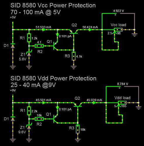
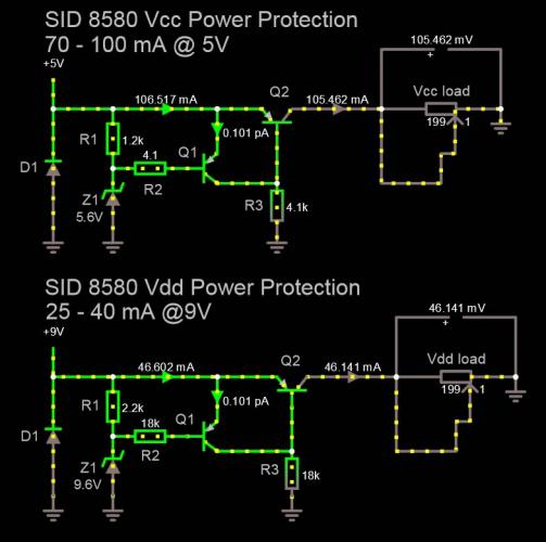
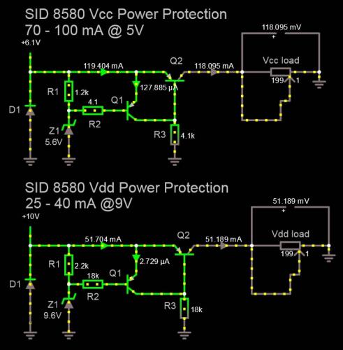
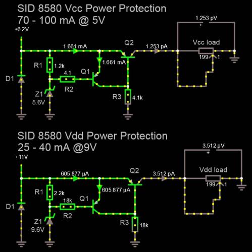
Hello everyone, Have been in the process of building my midibox SID for years now, but never seem to be able to get around it. Always concerned that once its built, it could be better. So I've been looking and gathering information about the best projects for midibox SID Models, different SID configurations, different front panel options, and most important, different power supplys. Currently trying to figure out the best way to supply my SID circuit, and this seems to be the best 2 options ou there: C64 transformer suplying a 9V linear regulator and a 5 Volt line directly from transformer to the SID Vcc pin Using a 12V-15V power supply to supply both a 9V linear regulator, and a 5V buck converter in parallel. Both of this options leave me a bit weary. Connecting the SID Vcc directly to the transformer would probably prevent me from having a good night sleep ever again, but also I'm not sure how this buck converter works out when bad stuff happens. I imagine that if the unlikely event of the Mosfet on the buck converter would blow up, it could act as a short circuit and expose the Vcc rail to whatever input voltage is receiving(Please correct me if I'm wrong). I've seen lots of Posts in the forum regarding this topic, and was wondering if I could get an engineer's input on the following circuit(no pun intended). A Google search for 'discrete over voltage protection circuit' will reveal this link as one of its first results: https://www.maximintegrated.com/en/design/technical-documents/app-notes/7/760.html The article from Maxim describes how the circuit works in great detail, but here's an overview: This simple protection circuit is composed by: - 3 resistors - 2 PNP transitors - 1 Diode - 1 Zener The circuit provides a power supply line with adjustable over-voltage protection, meaning that once the voltage at the input exceeds a certain level, the circuit will shut down its output power. The maximum current can also be programmed to certain extent by carefully selecting the transistors bias resistors. A simple reversed bias diode is used as a weak moderate protection against power line reverse voltages. I've simulated the circuit and carefully selected the components so that they meet the 8580 Chip Power limits specifications. I actually took this info from the 6581 datasheet, so not really sure if the same values apply, but good enough to use as a case study. 6581 Vdd pin = 9V 25-40 mA 6581 Vcc pin = 5V 70-100 mA I'm using 2 separate circuits in my simulation, one as a protection for the SID Vdd pin, the other for the Vcc pin. Here is the outcome of the following tests: Test 1: Ideal conditions - sim001_stable.jpg I feed the expected voltages(in range) into the circuits, using some moderate loads (around 200 ohm) to pull some current and everything works as expected. The pass transistor Q2 passes the amount of current required by the 200 ohm load, but also imposes a small voltage drop on the line so this should be taken into consideration. Test 2: Over current protection in action - sim002_heavy_load.jpg I started to simulate faulty conditions. First I decreased the resistance of the loads progressively until I reached their smallest possible value (around 1 ohm), so that maximum current is pulled from the pass transistors Q2. After the load resistances goes lower then a certain value, the current through the pass transistor Q2 is kept the same, and does not go higher as it is limited by resistors R2, R3 and transitor Q1 which controls the current flow in Q2. Test 3: Extreme limits near tip off - sim003_heavy_load_over_volt.jpg I started raising both Voltages at the circuit inputs until near their tip off points.The load resistance level was kept the same, so that maximum current flow is expected. In this scenario we can see the maximum current that the circuit will allow to pass, just before its tip off point. For Vcc, when there's a slight over voltage condition, the maximum allowed current will be around 20 mA more then its rated max limit of 100mA. For Vdd, when there's a slight over voltage condition, the maximum allowed current will be arounf 10 mA more then its rated max limit of 40mA. This upper limits are carefully set as to provide some wiggle room for the IC current requirements. Test 4: Over voltage protection in Action - sim004_over_volt_shutdown.jpg I continued to raise the input voltages above their tip off points (6.2V for Vcc and 11V for Vdd). Once the input voltage exceeds the tip off voltage, the circuit cuts off the pass transistors shutting down the power lines to the IC pins. The transistor is kept off until the input voltage level is set lower then its tip off point. Although I seem confident about this circuit's performance, I'm not an engineer, so it would be really great if someone with more expertize could give me their input on how great(or great disaster) would this circuits be as a power protection for the SID power pins. Not so sure this circuit would provide a nice output impedance for the SID chip to work as naturally as possible, without any restraints. What do you guys think? Also, does anyone out there knows the Absolute Maximum Ratings for the 8580 chip? Kind regards, analog_mo
- 5 replies
-
- sid 8580
- power supply
-
(and 1 more)
Tagged with:


