Leaderboard

Popular Content
Showing content with the highest reputation on 01/11/2014 in all areas
-
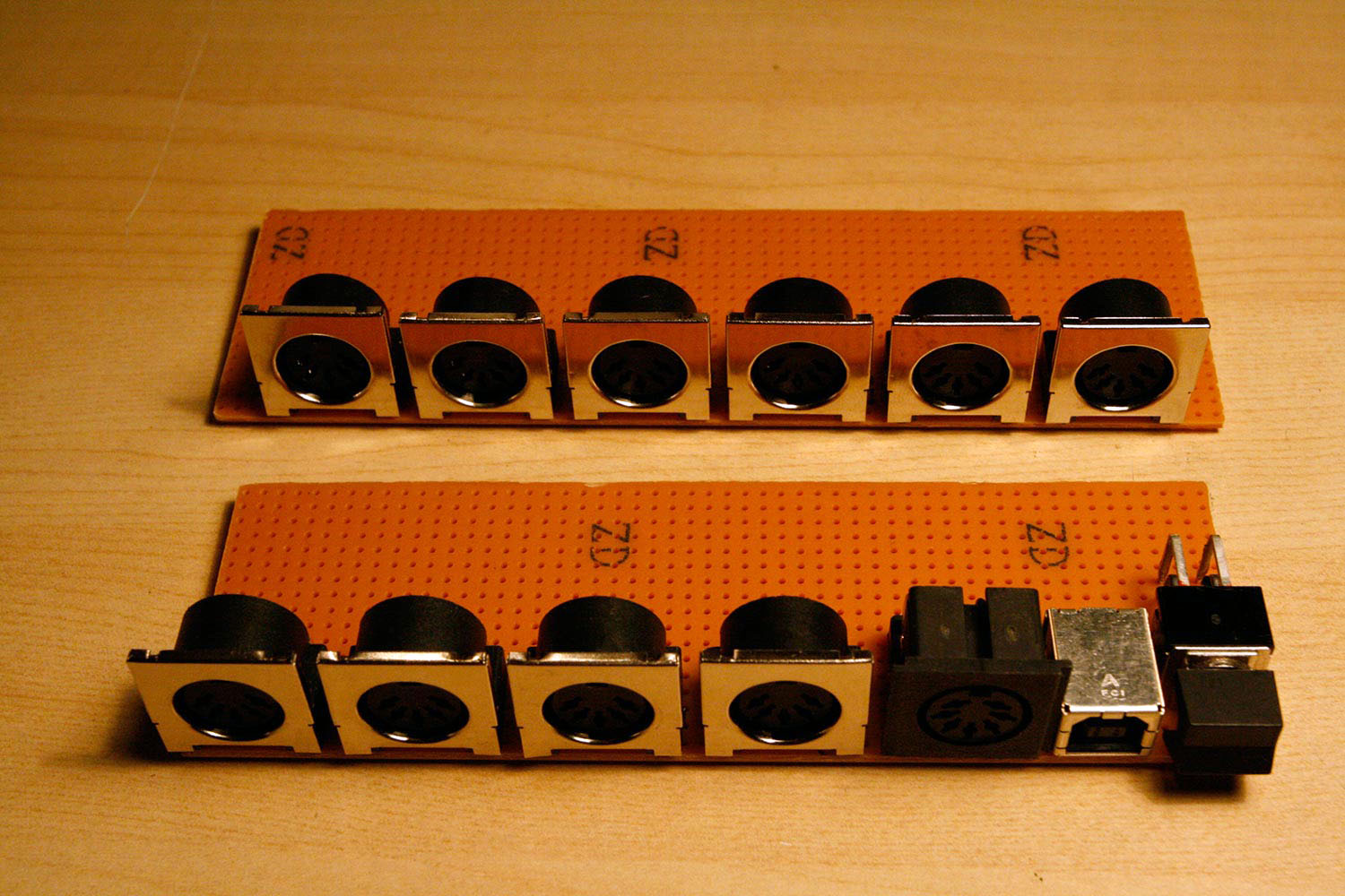
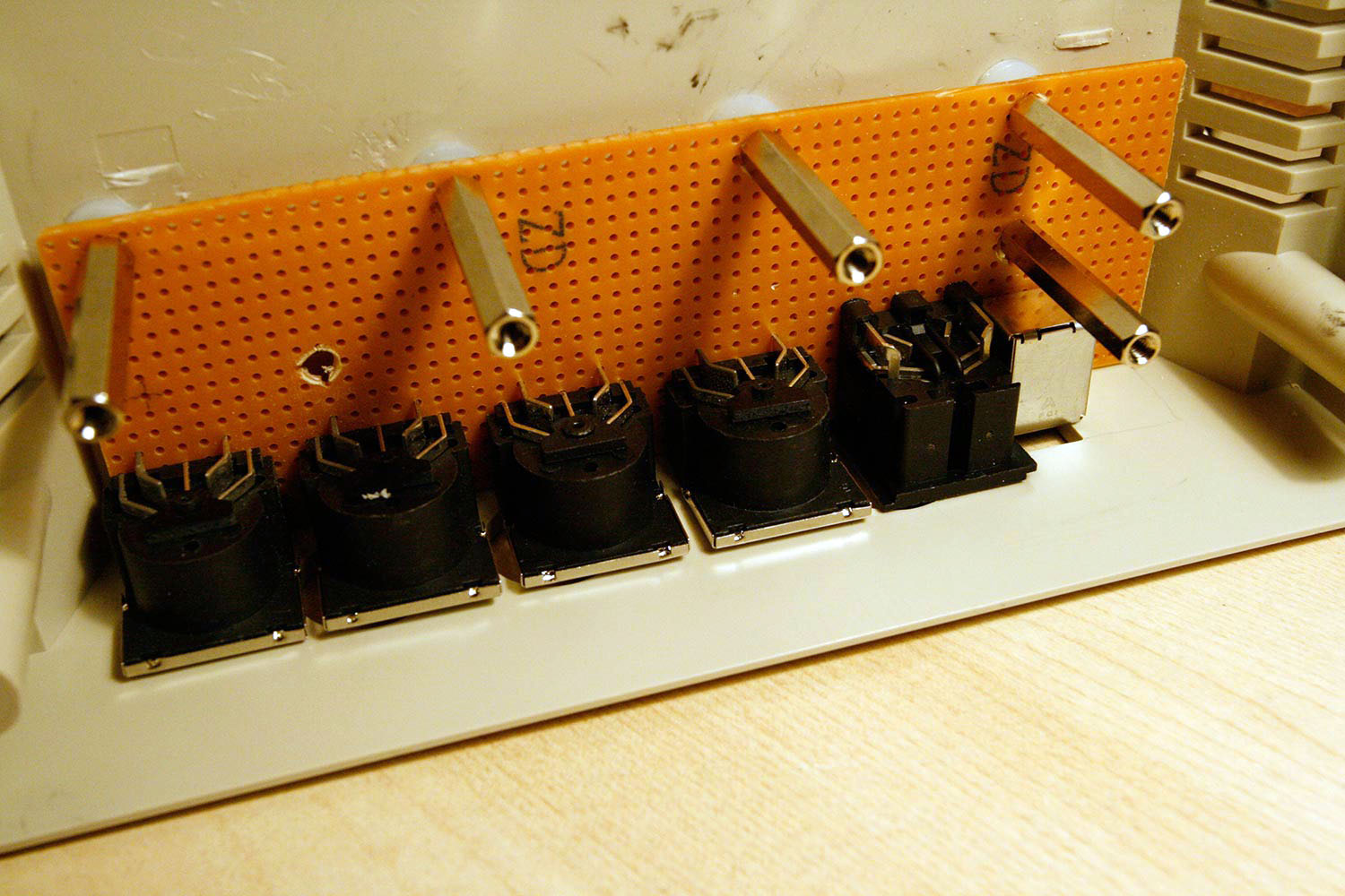
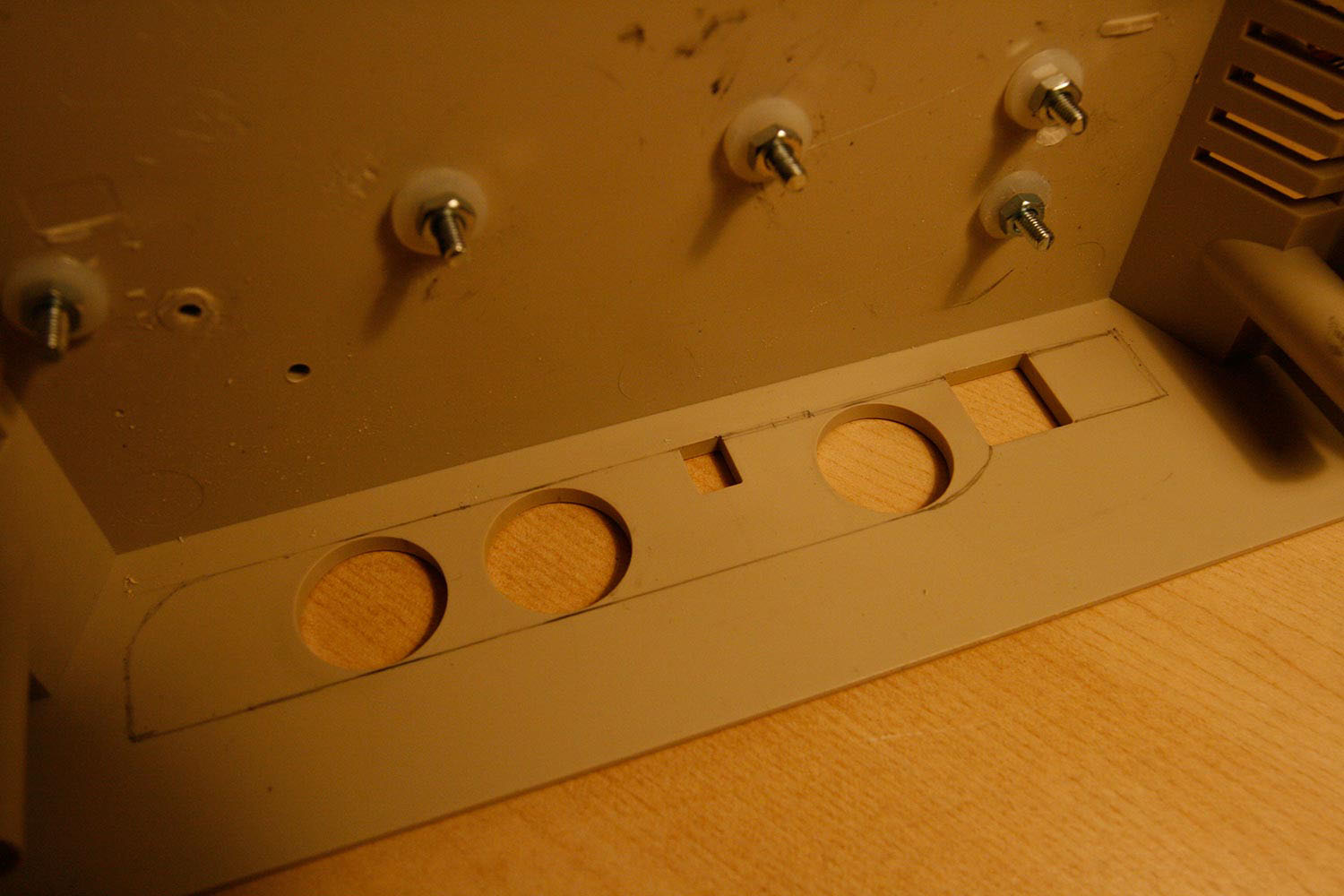
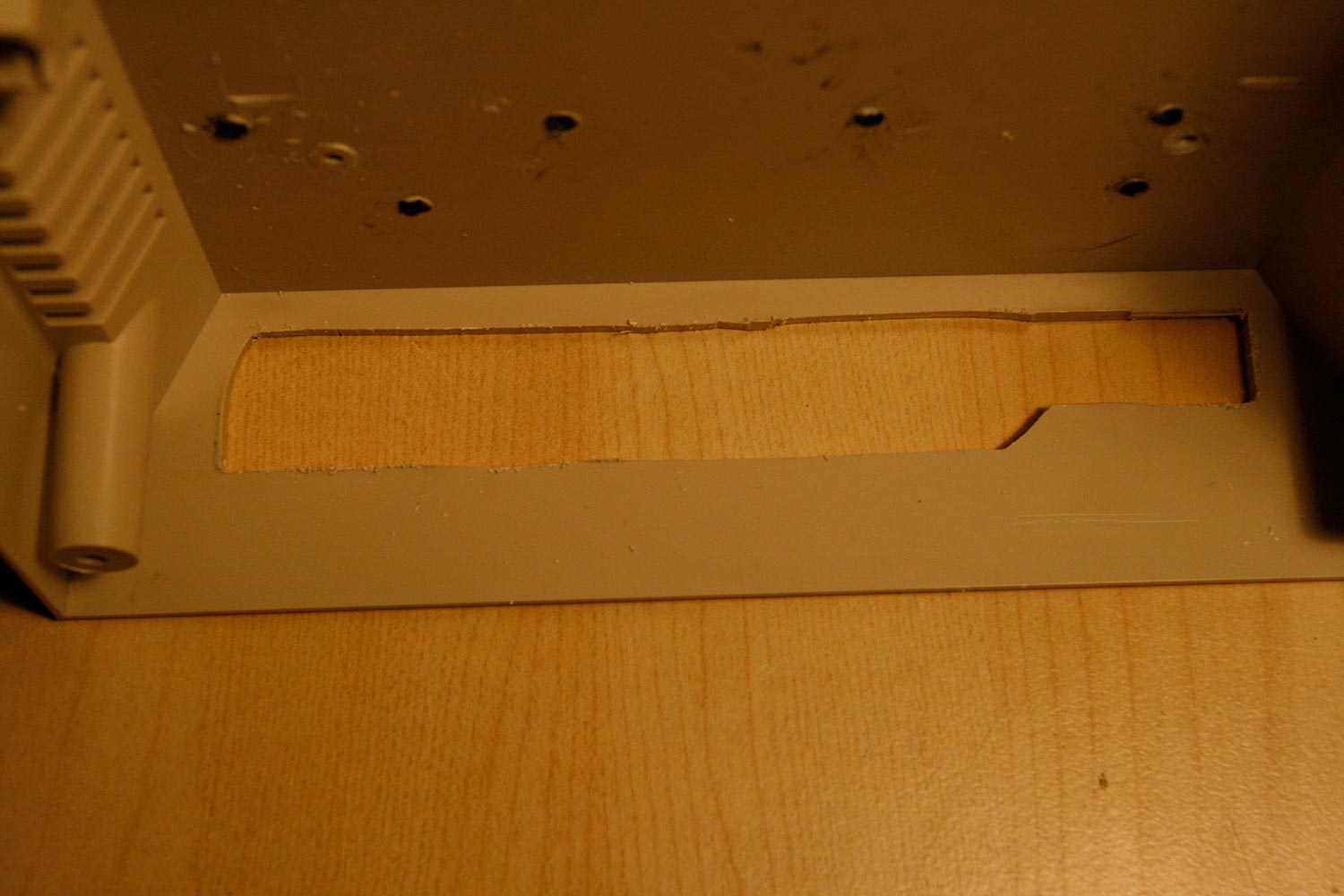
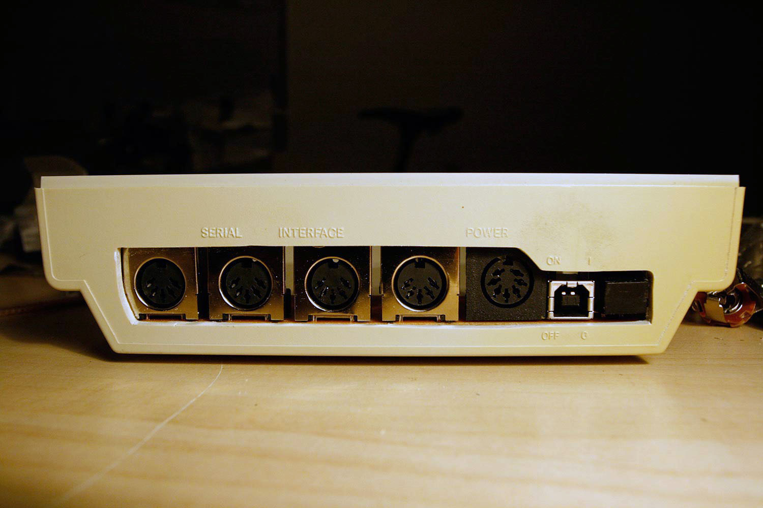
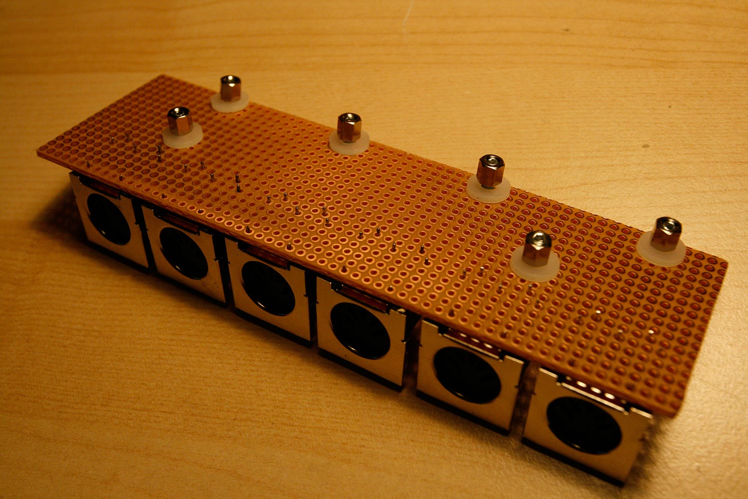
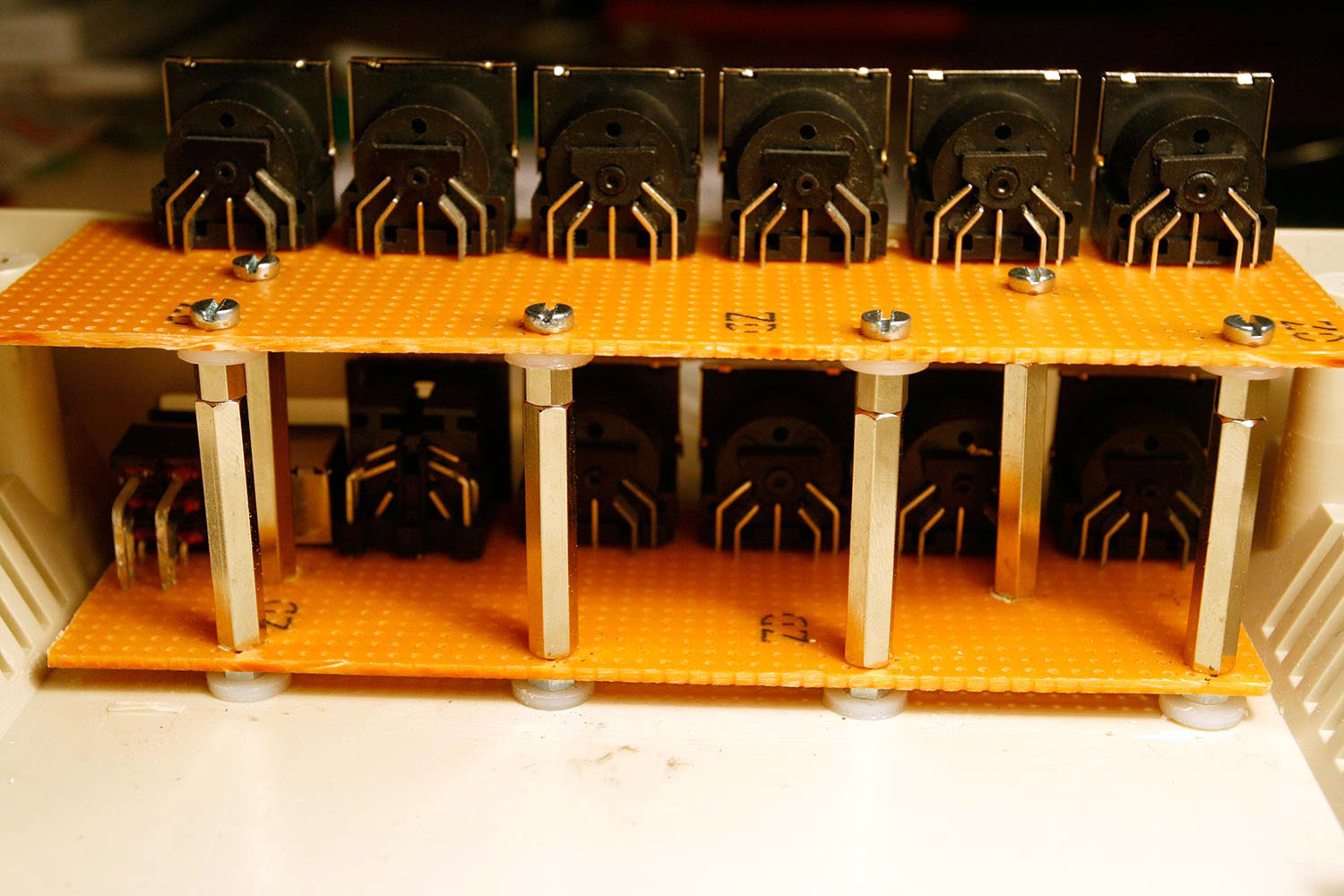
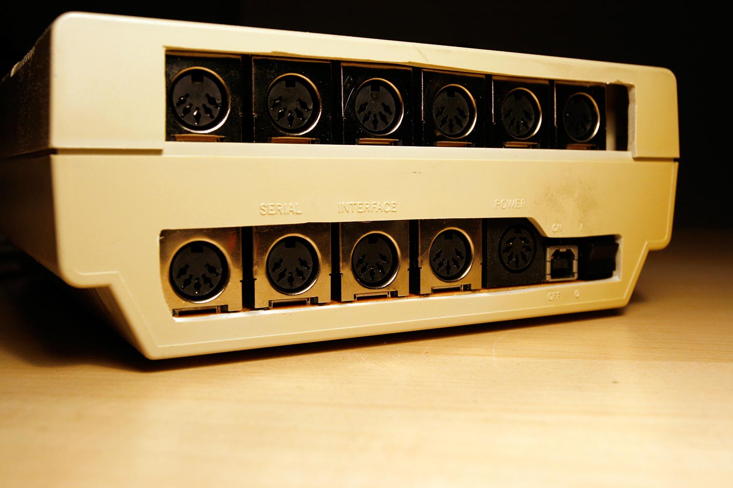
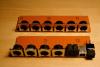
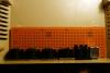
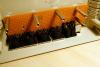
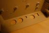
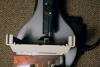
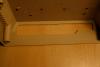
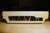
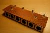
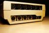
Step 6: Core Case Works: Preparing for the MIDI Socket Backplanes Parts used: 1541-II case (from step 1) 1541 Power Switch (from step 1) 1541 Power Jack (from step 1) 10x15cm Vector board (Any electronics store or Reichelt) 10x PCB-mounted MIDI jack (e.g. AVI Showtech, can use the MIDI jacks that were part of the Core32 module package and the MIDI IIC module packages) 6pcs M3 nylon washer (any mechanical store or Mouser) 6pcs M3 nut (any mechanical store or Reichelt) 6pcs M3x12mm screw (any mechanical store or Reichelt) 6pcs 5mm M3 hex standoff (any electronics store or Reichelt) 6pcs 30mm M3 hex standoff (any electronics store or Reichelt) Bench drill or hand drill with 2mm, 3mm and 4mm drills Dremel tool with cutting wheel (Mechanical) fret saw or hot wire cutting tool Sanding Paper (K180 class) attached to a flat thin surface Mechanical pencil (0.5mm) Description: * Using the dremel with a cutting wheel, create two pieces of vector board with sizes 150x45mm and 138x45mm. Save the 10mm residue. * Test component placement on the vector boards as shown in photo 1. Use a 2mm drill for the stabilizing pins of the usb socket. Remove the power switch again. * Mark a few standoff zones as shown in photo 2 and use a mechanical pencil to draw the drill positions in the case. Drill the case and with a 2mm drill, then with the 3mm drill. Also make sure that the standoff positions do not conflict with the 1541-II rubber feet... I had to relocate the position for the lower left standoff hole. Drill the standoff points on the vector board with a 3mm or 4mm drill. * Test-install the lower backplane by inserting 12mm M3 screws from the bottom, add a plastic washer and a M3 nut to achive the correct height, then add the backplane vector board, and then a 30mm standoff (photo 3). * Draw in saw zones for the fret saw with a pencil by turning the assembly on the side and estimating required space. Remove the backplane again (photo 4) and saw. You can use a fixed guide for the linear saw movements (photo 5), but it will likely not be 100% perfect (photo 6). Use sanding paper on a flat thin surface to correct the worst irregularities (photo 7) * Drill the upper vector board (I used a 3mm drill this time, as the 4mm was a little big) and test-install the upper connector backplane by adding a row of 5mm hex spacers and plastic washers on top of the 30mm spacers, adding the vector board screwed with 12mm screws (photos 8 and 9) * Repeating the above steps, mark the saw zone of the 1541 case top, saw, sand and install (photo 10). Note, that for extra bling, I decided to leave some room on the right side of the upper vector board for a later LAN port extension - therefore the larger cut out. Behold the world´s - first 1541-II with USB connector and 10 MIDI ports. :-).

 1 point