

Thomasch
-
Posts
129 -
Joined
-
Last visited
-
Days Won
1
Content Type
Profiles
Forums
Blogs
Gallery
Posts posted by Thomasch
-
-
I don't own a RD-8, but i'm interested to buy one at a later point.
On gearslutz.com there is a thread about modifications for the RD-8 and i just asked Maffez, who is the person that comes every day with new ways to mod the RD-8 around the corner.The RD-8 seems to become a great success for Behringer. Seems they can not produce them as fast as they sell them. The first batch was completly sold out, after a couple of days.
But with a price tag of only € 299 i don't wonder, when people buy these devices like crazy.
-
Just want to share, that the new Behringer RD-8 drummachine is using a STM32F405.
Maybe MIOS is an option as an alternative Firmware for those of you who own one. -
@Psykhaze
What happened to this project?
Was it abandoned? -
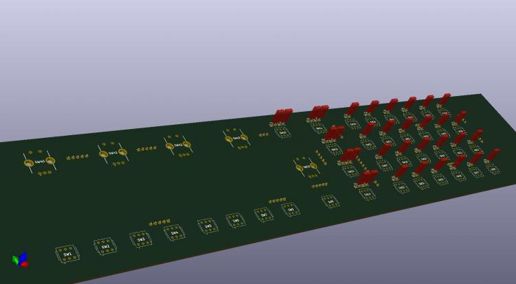
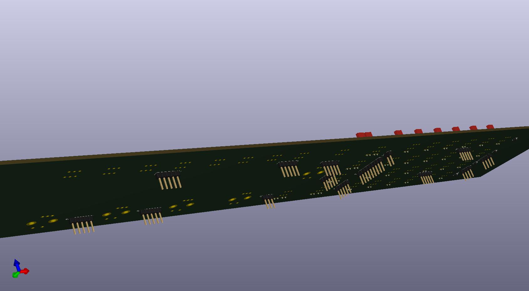
I tried to create something with the SRs directly on the board - there is really little space between all the switches. :D
With a classic Diode Button matrix it would make much more sense and i could choose between much more available switches/button caps.
Not to say, that spst switches might be cheaper and easier to wire.
It would also make much sense, to change the wiring of switches and encoders to different SR and SR pins, to bring the SRs closer to where they needed and to avoid a spidernet going from everywhere to everywhere across the board.I made a new schematic utilizing a 4x6 diode button matrix, that might be more efficient than the standard wiring.
It uses 4x 74HC165 SRs (DIN) and 3x 74HC595 SRs (DOUT). I will use SO-16 Packages.
For the resistors i'm not sure which package might fit best, maybe a resistor array might be the best choice, for the ease of soldering.
Atm i'm just sourcing which package type for the array might take the least space, while still being solderable by hand. Any advices?In a next step i would like to change the behavior of the "Ins/Op Select" and the 4 "Ins/OP [1...4]" buttons and would like to replace them with a 2x4 matrix for 8 dedicated "Instr [1...4]" and "OP [1...4]" buttons.
But all this is worth nothing and becomes a dead end eventually, as long as i'm not able to modify the code.
I downloaded Notepad++ and the toolchain explained in the wiki, but when i dig into the files i do understand nearly nothing, i'm a complete programming rookie...
I didn't even understand how to compile - but i'll try hard.Is someone willing to help me with the configuration and compiling of the code?
-
Yeah, in case i would do that, i would only use SO-16 packages, the DIL-16 used on the DINX4/DOUTX4 are way to big.
Using smd resistors would be mandatory too, to be able to fit that to the board.Do you think theres someone who want to build one of these boards too?
If anybody want to join in, just write a message here.Unfortunately my programming skills are near zero,but in case someone could help out and adapt the code for more inputs, i could change the whole approach with spst switches instead of the dpdt ones and some additional changes to the button layout.
I would just have to chain some more shift registers.
Anyway, i still do not know if that is even possible, because from what i remember reading here, the actual code is using almost all memory with some lonely free bits left. -
10 minutes ago, Antichambre said:
@Thomasch it's clear now... Rows are matriced, Columns are not.
I suppose you talk about Vs instead of Vc, and yes it's a ground, you can connect Vs bus to ground or Swithes pin directly to ground, it doesn't matter.
You can maybe put all the ICs(DIN/DOUT) on this PCB, and connect your CS directly to the Core. It will be cheaper, it will take less space and limit the number of interconnections.Ups yes, that was a typo, i meant Vs, i will fix it in the original post.
It's not a bad idea, to include the DIN/DOUT directly to the frontpanel pcb. But on the other hand, i have DINX4/DOUTX4 boards still in use with the actual setup of my MIDIbox FM, so no need to build it again.
-
The Pin Headers will connect to a DINX4 and a DOUTX4.
No need to add even more resistors.
Its basicly the standard wiring for the extended Frontpanel.Only difference is that i used 24 dpdt switches for the 4x6 matrix.
To be true, its not really a button matrix. In the original design every row has a switch and every column too.
My dpdt switches will work as if you press 2 buttons, (a row and a cloumn button) on the original design.
So if i press any of the button in the first column, one of the double poles on the switch will always connect the MCol1 labeled pin to Vs. (DINX4)
The other pole of the switch will connect MRow (DINX4) and MRow1, MRow2, MRow3 or MRow4 (DOUTX4), depending on wich of the 4 buttons in the row you have clicked on.
I use the dpdt switches to avoid coding for more shift register inputs, because i have no clue of coding.
Otherwise i would have also changed the "Instr./OP Select" button and the 4 "Instr/OP1-4" buttons to 8 dedicated "Instr1-4" and "OP1-4" buttons. -
I have a question regarding Eeschema (i use KiCad).
I wired all Vs connections to the bus, is that ok or should i use ground symbols instead of connecting Vc to the bus?
I ask, because i have no clue, if Kicad might build it's ratnest differently, when it has to wire a ground line, or maybe theres any other reason i didn't tink of, not to wire Vc to a bus. -
The DPDT momentary switches i will use, are much taller than most tactile switches and i realised, that there might be a problem with the height, because the rotary encoders are too short to have switches and encoders on one board.
It seems i have to make 2 small extra pcbs for the encoders and put them on shorter spacers, to get them closer to the prontplate.
This sucks a little bit, because it will need more space for additional screws and some additional pinheaders.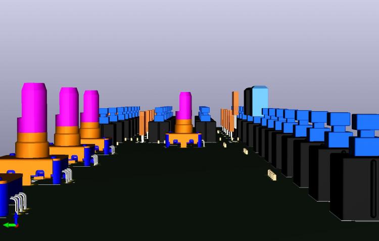
-
On 13.7.2019 at 6:47 PM, latigid on said:
You could always get a panel laser cut, that way the corner radius could be 0.15mm or less. That's fairly much square. If you push the LEDs through, the corners might also be "shaved" off in the process, no issue!
Might not be the best solution to push the LEDs into the board with force, because they are mounted on a pcb and the resulting force will bend their legs.
On 13.7.2019 at 6:47 PM, latigid on said:We stock a quality white OLED. Simplest would be to use this with a red acrylic "gel" or even have the whole window milled from transparent red acrylic.
Good hint, to use a white Oled with a transparent red acrylic window!
On 13.7.2019 at 6:47 PM, latigid on said:Are you using MIOS8 or MIOS32? The OLED driver works for MIOS32 but I don't know about MIOS8.
It's a MIOS8 core on a PIC18F4585.
Maybe @TK. can tell us if it might work?
@latigid on When you tinkered around with these OLEDs, was it possible to use them just as a pure hardware replacement instead of a HD44780 LCD display or did you had to change something in the code to make them work on your core32?On 13.7.2019 at 7:16 PM, Zam said:The "round" with 1mm milling tools represent 15/100 "error" at tangent
also, 5x3mm milling for 5x3mm LED will probably not fit, you need anyway little room for "soft" mounting
5.3x3.3 mm cutout with 1mm tool (0.5mm round at corner) is fine and you'll probably never notice 15/100mm room around the led.
Then there is the option to mill "inside" the corner, don't know the name of this technic, but it work too, close to unnoticeable by eyes with 1mm tool
Best
Zam
My english is not the best, , so what means 15/100 error at tangent?
I understand it in a way, that there will be a tolerance of +- 15%?
It would be cool to fit the LEDs without any gap into the frontplate, because gaps are always pulling dust like magnets (and they are hard to clean afterwards).
Because of tolerances a little bit of gap between hole and LED might be necessary. Just enough, that it don't needs any force to slide the LEDs in.
I might have to add a bevel to the cutouts from the backside, to give the LEDs a little lead sliding into the cutouts.
I'm sure this will prevent a lot of frustration while installing the pcb to the frontplate eventually. -
I want to use rectangular 2mm x 5mm LEDs, because they look so much cooler than the regular round ones.
But i realized quickly, that traditional CNC milling will always make rounded edges on the cutouts in the panel, with the size of the diameter of the milling tool.
This will make it hard to fit a rectangular LED into the cutout without adding additional gap width to the cutout or sanding the edges of the LED.
I will have to checkout if laser cutting, punching or something else might be the solution for my problem.
Any hints from the more experienced case builders are highly welcomed.When i dived into the deep of the web for sourcing parts, i ran into those nice 40x2 OLED displays with WS0010, RS0010 and OLED-0010 controller.
Would be nice to use one of these OLEDs on my build.
Are the WS0010/RS0010/OLED-0010 OLEDs compatible with the HD44780 driven LCD Displays that we typicaly use on the MIDIbox FM?Actually i'm looking for a red 40x2 OLED for a little bit of DX1 touch, but it seems there is no red one.
Has anyone found a red 40x2 OLED somewhere? -
Hi folks.
I've build a MIDIbox FM years ago and had a lot of fun with it in the last years, but i've never taken the time to design the beautiful case that this synth deserves.
It might have to do with the fact, that building something really cool would make the sausage casing more expensive than the sausage.However, in the last days i came to the conclusion, that now it's the time to build something nice and i started with it.
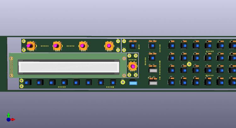
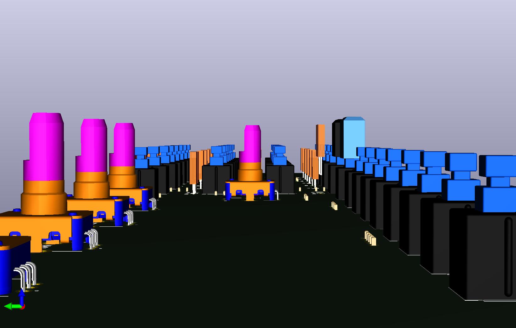
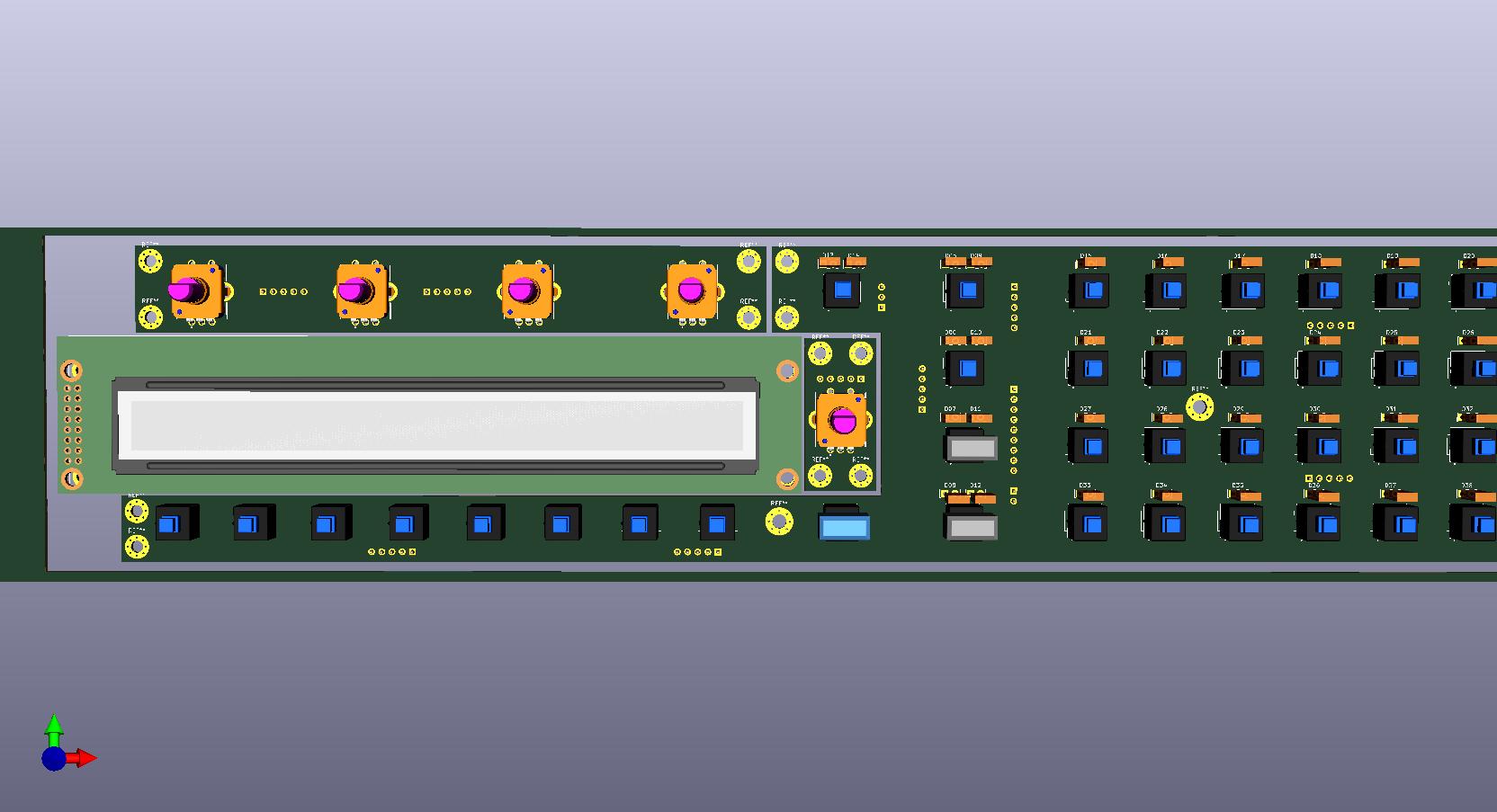
Unfortunately i never made a professional designed PCB by myself, but this time the handwired strip boards i used with my projects in the past wont do the trick.Same goes fpr 3d design and cnc milling of the frontpanel, never done anything like this.
Actually i'm in the process of learning KiCad and FreeCAD and as i quickly realized, there are a lot of other skills and knowledge i have to learn before.The goal is a 19" case with the extended user interface.
The matrix row/column buttons of the original expansion design will be extended to a dedicated button for every single function.
To make this work without having to change the code, i want to use DPDT tactile switches, which are really a rare breed out there.Here are the first results of what i've learned until now:
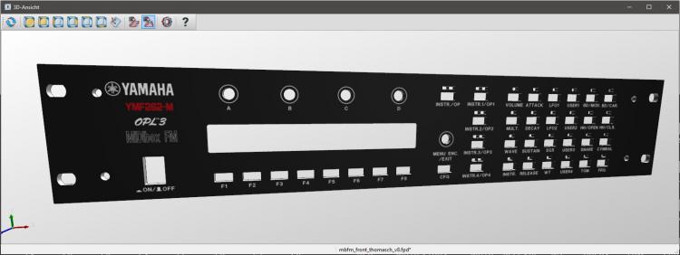
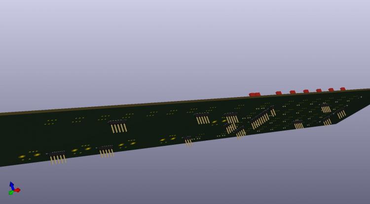
-
Hi all and a happy new year.
I'm just courious, because the basic version still sounds quite nice and i would love to see a vst version with tweakable knobs and buttons, but - is this project dead or just on the bottom of your priority list Thorsten?
Best Regards,
Thomasch-
 1
1
-
-
Or check this - 5pol din for 0,35€/piece.
https://www.musikding.de/DIN-Buchse-5-polig-Print
EDIT:
Just saw, they are out of stock. maybe it makes sense to email the shop owner. -
Hallo Rolf.
Mir gefällt dein Synth recht gut. Schade, daß er nur monophon spielbar ist.
Soundmäßig deckt dein Synth nen Haufen Sounds ab, daß man sie nur monophon nutzen kann schränkt den Nutzen allerdings grob auf Bass- und Lead Sounds ein. (Es mag Ausnahmen geben)Hast du schon Pläne für einen DeGenerator 2 mit polyphoner/multitimbraler Soundengine und Einzelausgängen?
-
-
Hallo Rolf,
das neue UI Design des Sequencer-Arppeggiator ist dir wirklich sehr gut gelungen.
Sehr viel übersichtlicher als die vorige Version.Eine Kleinigkeit die ich evtl noch ändern würde, ist die Bezeichnung des Notenwerts H.
Die Bezeichnungen aller anderen Parameter des User Interface sind in englischer Sprache, daher würde ich an deiner Stelle auch bei der Bezeichnung der Notenwerte auf den englischen/internationalen Standard zurückgreifen.
Hier würde ich an deiner Stelle aus dem H ein B machen.
Das gleiche gilt dann auch für den "deutschen" Notenwert B, der internatonal als Bb geschrieben wird.Beste Grüße
Thomasch -
Normale Unterlegscheiben schützen das Rack leider nur vor den Schraubenköpfen, Schäden durch das Gewinde der Schraube werden damit leider nicht verhindert.
Ich suche etwas in der Art wie auf der Skizze um ein Einschneiden des Gewindes zu vermeiden.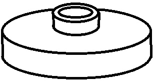
-
Too sad...
It could become a cheap DIY 16x16 MIDI In/Out USB Interface.But what i don't understand is, why do they not produce their own interface brand?
Everything is more or less developed and all they have to do is ordering some printed PCBs and cases in china.
Instead it seems they only provide a licence solution for 3rd party manufacturers.
Is the market for their MIDI Interfaces that big, that they want to share it with the handfull of other manufacturers?However...
-
Hi Leute,
Mich würde mal interessieren welches die besten Methoden sind, um 19" Geräte schonend ins Rack zu schrauben.
Und zwar ohne böse Kratzer oder abgeplatztem Lack.
Konkrete Produkt Links zu möglichen Lösungen wären prima.Gruß
Thomasch
-
On 10.2.2017 at 5:21 PM, Altitude said:
MOQ is 500pcs on the new chips (2500 euro), board design is also way more complex. Kind of hard to justify a DIY version when you can buy one fairly inexpensively
When i called Ploytec i forgot to ask about prices and minimum order quantities. Did you called them too or where did you got the number of 500pcs MOQ?
500pcs is a heavy number for DIYers like the MIDIbox community.
No idea if there will be smaller amounts possible in the future or by request.
With 2500€ per 500pcs, 5€ seems to be a fair price for one of these memory chips with the software on it.Unfortunately the linked interface make use of only 8x8 MIDI In/Out instead of the possible 16x16.
Lets wait for what kind of news will come with the mainboad the employee mentioned on phone.
Maybe things will become more interesting to us, when its released and more informations are available.
At least this mainboard will free us from soldering 0.4mm pitch... -
CTRLR is a good candidate or every other VST or standalone App that uses the same MIDI Device
-
Ableton and MIDI...
What you describe sounds like the inability of Ableton to allow Multiclient MIDI
If you try, the driver hangs up. -
The Dude from Ploytec told me also, that the USB3 midijunction 16x16 will have shorter latencies than the GM5


Yamaha YMF825 - 16-voice polyphonic FM synthesizer - 29 on-chip operator-waveforms and 8 algorithms
in MIDIbox FM
Posted
Hi folks,
i never heard something about the YMF825, is this a newly released Yamaha chip?
16-voice polyphonic FM synthesizer
29 on-chip operator-waveforms and 8 algorithms offer a whole variety of sound
Synchonous serial data link for host controller interface
Integrated loudspeaker driver (also supports external amplifier connection)
Integrated 3-band equalizer
Integrated 16-bit monaural DAC
Integrated power-on resetFlexible Power Supply Configurations
https://device.yamaha.com/ja/lsi/products/sound_generator/images/4MF825A40.pdf