

novski
-
Posts
460 -
Joined
-
Last visited
-
Days Won
5
Content Type
Profiles
Forums
Blogs
Gallery
Posts posted by novski
-
-
Ich verstehe was du meinst aber leider musste ich die gleiche Erfahrung machen. Es braucht viel aufwand um den durchblick über all diese Platienchen und Bausteine zu bekommen. Ich rate dir diese Zeit auf dich zu nehmen und die ucapps Seite eingehend zu studieren. Die Möglichkeiten die du dir damit an eignest sind riesig und mit Programmier Erfahrung bist du mir einen schritt schon voraus. Fange mal mit dem Core an: http://www.ucapps.de/mbhp_core_lpc17.html
Du wirst schnell merken das du dazu noch Inputs für Knöpfe oder Encoder (Endlos Regler) brauchst: http://www.ucapps.de/mbhp_din.html
Und nicht zu letzt wirst du Visuelle Feedback Anzeigen brauchen wie LEDs: http://www.ucapps.de/mbhp_dout.html
Ein LCD Display ist ganz Praktisch: http://www.ucapps.de/mbhp_lcd.html
Ganz gut ist das neue wiki auch gelungen: http://www.midibox.org/dokuwiki/
Darin findest du Antworten auf System fragen und vieles mehr.
Hoffe das hilft dir etwas.
ach ja und den Bausatz musst du dir bei smashtv bestellen: midibox-shop.com
Das dauert etwas aber die Qualität ist bei smashtv am besten.
Liebe Grüsse
novski
-
CORE (midi out) -----------> (midi in) MB_MF 1 (midi out) -------------> (midi in) MB_MF 2 (midi out) -----------------> (midi in) CORE
is that correct?
Yes, correct.
MB_MF 2 is the endpoint i think.
But i think you don't need to be worried about damaging something by miss cableling Midi signals...
The Calibration is done in the MIOS Studio MBHP_MF_NG TOOL. There you can assign a MF_NG Module by its Device ID.
How to Define those parameters in NGC seams to be not documented until now. If it is possible anyhow...
Have a nice day!
novski
-
Im shure he will reply soon.
His village got in to a tornado last month. So he might be busy helping out...
-
not required as long as you don't touch the pins ;-)
Wold it be more secure to connect those Touchsensor pins to a 1MOhm instead of the R16-19 (47k) Resistor?
Or are those sensors de-connected in software any way, as soon as i configure the MF_NG for 1 Fader?
The second thought is to leave out the IC6 (74HC165 for Touch) completely. - What consequences wold that have?
Thanks
Novski
-
Looks fine to me. Did you draw a schematic yet?
what buttons are you going to use?just found your other topic... i don't know snap-in buttons...
regards,
novski
-
Depends on Weight. How many do you need?
Just checked some regions now.
I live in Switzerland and will always think in CHF. Because of exchange rate fluctuations these Prices can vary... so PM me for exact price by the time you want me to ship.
Most package in EU smaller than 500g is around Euro 14.-
So for max. 25 Faders for Shipping cost is Euro 14.-
more than 25 Faders are around Euro 17.-
close EU: 10-12 Days
<500g = around Euro 14.-
>500g - 1kg = around Euro 17.-
>1kg - 2kg = around Euro 27.-
USA: 15-20 Days
<500g = around $ 22.50
>500g - 1kg = around $ 28.50
>1kg - 2kg = around $ 42.50
One Fader is 14g
These are the lowest rates i can get in Switzerland.
Packaging is about 150g.
-
no problem.
Just for information: the pins you used are for the DOUT modul connection.
They are bypassed over that pcb to make it possible to chain DIN and DOUT over a single DIL (Dual In Line) Ribon Cable...
cheers,
novski
-
i can't follow you.
there is a default .NGC witch will be loaded automatically. If you don't want to load automatically you can "set autoload off" (more in the help by tipping "help" in to the command line of MIOS32 application...)
hmm, i just recognized that you connected the cables on J1 to the inner row. Try the outside row.
-
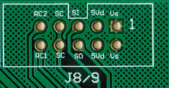
I scanned my PCB before soldering, i will attach it, so you can see the names of the Pins you are connecting.
Also check if you have bad connections. I can see pinheads with something on them like a D-Sub Female connection stuck in a Pinhed-female - why?

-
There is a first steps tutorial on ucapps.de
Klick on Midibox_NG
Ther you can find all informations about signaling a button.
Best regards
Novski
-
he. ucapps.de site is down... :sad:
in the wiki you can find it as a page. http://www.midibox.org/dokuwiki/doku.php?id=MB-LRE8x2CS_PCB
novski
-
Better ask that in embededsystems forum i think...
-
This Phil explaned to me once... (its in the same tread one page further...)
so yea. Cheers
novski
-
Hi I had that problem. Its discussed here: The app wan't transmitted correctly because of a midi usb cable that doesn't transmit Sysex correctly. I cant emagine that you use a cheap usb midi cable since midibox_ng is running on 32bit systems only... Did you load the motormix protocol throu mios studio - mf_ng window?
-
Well, 51.32 Euro isn't the price i found, because the Swiss Conrad online store has it for CHF 92.95 which is Euro 76.3 there for, i thought its expensive...
Living in a wealthy Island has a backhand side...
Cheers,
Novski
-
Ahh! - Now i got it. Thanks a lot.
Best Regards,
Novski
-
OK. Thanks TK.
Then, i have one more Line to the DC Connection on the Displays. On Display 1-8 its connected parallel to the SERIAL IN (Pin 14) of the First Shift-register, also called RS on J15.
Is the second Shift-register Serial IN (Pin 14) connected to the DC line like the first 8 Displays or is the DC line to be connected to the Serial IN of the first Shift-register?
In short: is DC of Disp 9-16 connected parralell to Serial IN of first SR or second SR?
Im neither an Electronic Engineer nor a Software so please don't hesitate to correct me but:
I think that there is a difference in Time (clock) between those two of one bit (from IN to OUT?) and because the D0/1 are clocked with the first SERIAL IN line i do not know what cold happen if i eventually ad another 8 Displays or more.
Best Regards
Novski
-
Boothold, exactly. But i have connected the RW from J15 also to D1 as drawn in this schematic:
http://ucapps.de/mbhp/mbhp_lcd_ssd1306_single_mios32.pdf
Same is the E line from J15 that is connected to D0 on the Displays. it has a 1k Resistor to GND as well.
I made a pdf of my eagle schematic that works for the first 8 Dispays and a pdf of the schematic im drawing named FaderSlave. You can see that there is a normal DOUT SR built up and D0,D1 are not connected to any other line than between them self. What i don't now is, where to connect those two lines D1 and D0.
Thanks for your Time
Novski
-
seams to be a quite expensive display... why did you select this LCD? Are there any special preferences you need?
maybe you want to check mouser or reichelt for a cheaper one...
-
Hi
I have problems figuring out how to connect additional SSD1306 displays on a second shift register for display 9-16.
I used the Pin 9 (Q8*) from the SR1 - for Serial IN, Pin 14 on the SR2. Then i connected SC (J28 Pin 8) to Pin 11 and RC (J28 Pin 10) to Pin 12 on SR2
Now i looked at the existing SR1 and see that there are more connections. There are connections between OE# and D1 on the Display that seam to be necessary but also over 1k to GND.
I want to be sure before i blow up one of my nice smal OLEDs...
Thanks
novski
-
Do i understand right?
Mirroring = It lets the LEDs go "ON" in the opposite direction (shift-register Outputs go Low in Opposite direction as without)
Inverting = It swaps the row and selector shift registers
Best Regards
Novski
-
Hi TK.
Wonderful! it was the Inverter... The Polarity is equal to fairlightiiis pcb.
But i designed just 15 LEDs because for Audio Panorama functionality i want a Middle "single" LED.
Now the Middle point is decreased to left. I expected it to increase to right because the LED missing there. (my LEDs are like fairlightiii's from left to right) Is that because of the Inverting?
Thanks a lot!
novski
-
I have problems with my LED Matrix.
I built it upon the Schematic of Fairlightiii's pcb but with just 8 Encoders and LED Rings.
By turning one of the Encoders all LEDs around the other Encoders go on, but the LEDs around the Encoder i turn don't.
And the brightness of the LEDs increase by Turning all the Encoders to 127.
Don't know where to start searching.
The PCB is correct, i checked that.
this ist my config .ngc for testing:
RESET_HW
LCD "%C"
LCD "@(1:1:8)OLED1"
LCD "@(2:1:8)OLED2"
LCD "@(3:1:8)OLED3"
LCD "@(4:1:8)OLED4"
LCD "@(5:1:8)OLED5"
LCD "@(6:1:8)OLED6"
LCD "@(7:1:8)OLED7"
LCD "@(8:1:8)OLED8"

# Buttons configuration

EVENT_BUTTON id=1   fwd_id=LED:1   type=NoteOn key=24  lcd_pos=1:1:1 label="^std_btn"
EVENT_BUTTON id=2   fwd_id=LED:2   type=NoteOn key=37  lcd_pos=2:1:1 label="^std_btn"
EVENT_BUTTON id=3   fwd_id=LED:3   type=NoteOn key=38  lcd_pos=3:1:1 label="^std_btn"
EVENT_BUTTON id=4   fwd_id=LED:4   type=NoteOn key=39  lcd_pos=4:1:1 label="^std_btn"
EVENT_BUTTON id=5   fwd_id=LED:5   type=NoteOn key=40  lcd_pos=5:1:1 label="^std_btn"
EVENT_BUTTON id=6   fwd_id=LED:6   type=NoteOn key=41  lcd_pos=6:1:1 label="^std_btn"
EVENT_BUTTON id=7   fwd_id=LED:7   type=NoteOn key=42  lcd_pos=7:1:1 label="^std_btn"
EVENT_BUTTON id=8   fwd_id=LED:8   type=NoteOn key=43  lcd_pos=8:1:1 label="^std_btn"
EVENT_BUTTON id=9   fwd_id=LED:9   type=NoteOn key=36  lcd_pos=1:1:1 label="^std_btn"
EVENT_BUTTON id=10  fwd_id=LED:10  type=NoteOn key=37  lcd_pos=2:1:1 label="^std_btn"
EVENT_BUTTON id=11  fwd_id=LED:11  type=NoteOn key=38  lcd_pos=3:1:1 label="^std_btn"
EVENT_BUTTON id=12  fwd_id=LED:12  type=NoteOn key=39  lcd_pos=4:1:1 label="^std_btn"
EVENT_BUTTON id=13  fwd_id=LED:13  type=NoteOn key=40  lcd_pos=5:1:1 label="^std_btn"
EVENT_BUTTON id=14  fwd_id=LED:14  type=NoteOn key=41  lcd_pos=6:1:1 label="^std_btn"
EVENT_BUTTON id=15  fwd_id=LED:15  type=NoteOn key=42  lcd_pos=7:1:1 label="^std_btn"
EVENT_BUTTON id=16  fwd_id=LED:16  type=NoteOn key=43  lcd_pos=8:1:1 label="^std_btn"
EVENT_BUTTON id=17  fwd_id=LED:17  type=NoteOn key=36  lcd_pos=1:1:1 label="^std_btn"
EVENT_BUTTON id=18  fwd_id=LED:18  type=NoteOn key=37  lcd_pos=2:1:1 label="^std_btn"
EVENT_BUTTON id=19  fwd_id=LED:19  type=NoteOn key=38  lcd_pos=3:1:1 label="^std_btn"
EVENT_BUTTON id=20  fwd_id=LED:20  type=NoteOn key=39  lcd_pos=4:1:1 label="^std_btn"
EVENT_BUTTON id=21  fwd_id=LED:21  type=NoteOn key=40  lcd_pos=5:1:1 label="^std_btn"
EVENT_BUTTON id=22  fwd_id=LED:22  type=NoteOn key=41  lcd_pos=6:1:1 label="^std_btn"
EVENT_BUTTON id=23  fwd_id=LED:23  type=NoteOn key=42  lcd_pos=7:1:1 label="^std_btn"
EVENT_BUTTON id=24  fwd_id=LED:24  type=NoteOn key=42  lcd_pos=8:1:1 label="^std_btn"

EVENT_BUTTON id=41   fwd_id=LED:41  type=NoteOn key=43  lcd_pos=1:1:2 label="^std_btn"
EVENT_BUTTON id=41   fwd_id=LED:25  type=NoteOn key=43  lcd_pos=1:1:2 label="^std_btn"
EVENT_BUTTON id=42   fwd_id=LED:42  type=NoteOn key=36  lcd_pos=2:1:2 label="^std_btn"
EVENT_BUTTON id=43   fwd_id=LED:43  type=NoteOn key=37  lcd_pos=3:1:2 label="^std_btn"
EVENT_BUTTON id=44   fwd_id=LED:44  type=NoteOn key=38  lcd_pos=4:1:2 label="^std_btn"
EVENT_BUTTON id=45   fwd_id=LED:45  type=NoteOn key=39  lcd_pos=5:1:2 label="^std_btn"
EVENT_BUTTON id=46   fwd_id=LED:46  type=NoteOn key=40  lcd_pos=6:1:2 label="^std_btn"
EVENT_BUTTON id=47   fwd_id=LED:47  type=NoteOn key=41  lcd_pos=7:1:2 label="^std_btn"
EVENT_BUTTON id=48   fwd_id=LED:48  type=NoteOn key=42  lcd_pos=8:1:2 label="^std_btn"

# Encoder configuration
ENC n=  1   sr=4 pins=0:1   type=detented2
ENC n=  2   sr=4 pins=2:3   type=detented2
ENC n=  3   sr=4 pins=4:5   type=detented2
ENC n=  4   sr=4 pins=6:7   type=detented2
ENC n=  5   sr=5 pins=0:1   type=detented2
ENC n=  6   sr=5 pins=2:3   type=detented2
ENC n=  7   sr=5 pins=4:5   type=detented2
ENC n=  8   sr=5 pins=6:7   type=detented2

# LEDring configuration
DOUT_MATRIX n= 1  rows=8 sr_dout_sel1= 7  sr_dout_sel2= 0 sr_dout_r1= 8 sr_dout_r2= 9

# Encoder events
EVENT_ENC id= 1  fwd_id=LED_MATRIX:1   type=CC chn= 1 cc= 24  lcd_pos=1:1:4 label="^std_enc"
EVENT_ENC id= 2  fwd_id=LED_MATRIX:2   type=CC chn= 1 cc= 25  lcd_pos=2:1:4 label="^std_enc"
EVENT_ENC id= 3  fwd_id=LED_MATRIX:3   type=CC chn= 1 cc= 26  lcd_pos=3:1:4 label="^std_enc"
EVENT_ENC id= 4  fwd_id=LED_MATRIX:4   type=CC chn= 1 cc= 27  lcd_pos=4:1:4 label="^std_enc"
EVENT_ENC id= 5  fwd_id=LED_MATRIX:5   type=CC chn= 1 cc= 28  lcd_pos=5:1:4 label="^std_enc"
EVENT_ENC id= 6  fwd_id=LED_MATRIX:6   type=CC chn= 1 cc= 29  lcd_pos=6:1:4 label="^std_enc"
EVENT_ENC id= 7  fwd_id=LED_MATRIX:7   type=CC chn= 1 cc= 30  lcd_pos=7:1:4 label="^std_enc"
EVENT_ENC id= 8  fwd_id=LED_MATRIX:8   type=CC chn= 1 cc= 31  lcd_pos=8:1:4 label="^std_enc"

# we've a single MBHP_MF_NG module with 8 motorfaders
# It has to be configured for Motormix protocol!

MF n=1  enabled=1  midi_in_port=IN2  midi_out_port=OUT2  chn=1  ts_first_button_id=2001  config_port=USB3

################################################################################

# on motorfader movements
EVENT_MF  id= 1  fwd_id=ENC:33  type=CC  chn= 1 cc=32  range=0:127  lcd_pos=1:1:5  label="^std_mf"
EVENT_MF  id= 2  fwd_id=ENC:34  type=CC  chn= 1 cc=33  range=0:127  lcd_pos=2:1:5  label="^std_mf"
EVENT_MF  id= 3  fwd_id=ENC:35  type=CC  chn= 1 cc=34  range=0:127  lcd_pos=3:1:5  label="^std_mf"
EVENT_MF  id= 4  fwd_id=ENC:36  type=CC  chn= 1 cc=35  range=0:127  lcd_pos=4:1:5  label="^std_mf"
EVENT_MF  id= 5  fwd_id=ENC:37  type=CC  chn= 1 cc=36  range=0:127  lcd_pos=5:1:5  label="^std_mf"
EVENT_MF  id= 6  fwd_id=ENC:38  type=CC  chn= 1 cc=37  range=0:127  lcd_pos=6:1:5  label="^std_mf"
EVENT_MF  id= 7  fwd_id=ENC:39  type=CC  chn= 1 cc=38  range=0:127  lcd_pos=7:1:5  label="^std_mf"
EVENT_MF  id= 8  fwd_id=ENC:40  type=CC  chn= 1 cc=39  range=0:127  lcd_pos=8:1:5  label="^std_mf"

# on touchsensor event (first id has been specified in the MF configuration above)
EVENT_BUTTON  id= 2001  type=NoteOn chn= 1 key=0x68  range=0:127  lcd_pos=1:1:6  label="^std_btn"
EVENT_BUTTON  id= 2002  type=NoteOn chn= 1 key=0x69  range=0:127  lcd_pos=2:1:6  label="^std_btn"
EVENT_BUTTON  id= 2003  type=NoteOn chn= 1 key=0x70  range=0:127  lcd_pos=3:1:6  label="^std_btn"
EVENT_BUTTON  id= 2004  type=NoteOn chn= 1 key=0x71  range=0:127  lcd_pos=4:1:6  label="^std_btn"
EVENT_BUTTON  id= 2005  type=NoteOn chn= 1 key=0x72  range=0:127  lcd_pos=5:1:6  label="^std_btn"
EVENT_BUTTON  id= 2006  type=NoteOn chn= 1 key=0x73  range=0:127  lcd_pos=6:1:6  label="^std_btn"
EVENT_BUTTON  id= 2007  type=NoteOn chn= 1 key=0x74  range=0:127  lcd_pos=7:1:6  label="^std_btn"
EVENT_BUTTON  id= 2008  type=NoteOn chn= 1 key=0x75  range=0:127  lcd_pos=8:1:6  label="^std_btn"
Any Ideas?
Thanks
novski
-
Hi
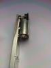
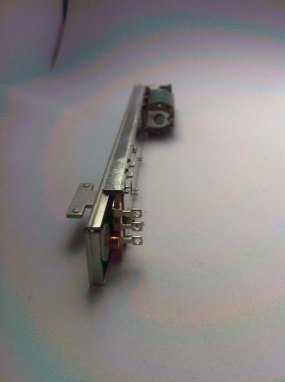
Im Selling 100 pice ALPS Motorfaders RSAON11M9AOK - Link to the Datasheet
Price is 15 Euro p. pice & Shipping. I will check the shipping cost if you send me a PM with Quantity and Address.
-for more than 30 Pice = 13 Euro p. Pice & Shipping.
It looks like this:
Best Regards
Novski


Upcoming MBHP_MF_NG module
in MIDIbox HUIs
Posted
http://www.midibox.org/dokuwiki/doku.php?id=midi_interface_blacklist
:smile: