Navicat
-
Posts
47 -
Joined
-
Last visited
-
Days Won
4
Content Type
Profiles
Forums
Blogs
Gallery
Everything posted by Navicat
-
Hmm that seems stolen from the TR-8060... I have something similar too this and i made it in SolidWorks 3D and also a nice faceplate. Best Regards, Tilemachos
-
Here is a velocity control for each voice module of a TR-808. The concept is simple.. What i did is i took the accent circuit from the original schematics and i place a digipot that will control the velocity for every single voice separately. A Digipot chain will be connected at J19 of the STM32F4 Core. Each Digipot is controlling the Velocity Value on each instrument. So let's see. A Pin from Dout module sends a Trigger of +5 Volts. One Branch goes at the Trigger in of the Voice module. The other branch is going into my circuit. The digipot controls the velocity level from +5 volts to +15v. ( Even with 0 Velocity a 5v minimum trigger must go in voice module so we have sound.) The result is a Trigger voltage from +5v to +15v that goes into the Accent in of the voice module. What we have here is a velocity control for every single note. :rolleyes: I Need help on how to programm Digipots to do this job. Here is the schematic Accent 5-15v.PDF Regards Tilemachos
-
AOUT_NG is using the TLV5630 12-bit voltage output DAC. It has 8 channels outputs for CV. I found that LMP92001 is the same but with 12 channel outputs for CV. I think that STM32F4 board can easy handle this IC since it is the same but with 8 more channels. Here is the Datasheet: http://www.ti.com/lit/ds/symlink/lmp92001.pdf I think it would be great to have 12 channel of CV. I am waiting for answers if it is possible to control this with mios and how to do this. I can fast make a prototype board ( spend money :P ) when answers are positive and i will share schematics and board files. Also i have a DIY SMD oven to bake the board. ( I already did 0201 resistors soldering with my oven) Regards Tilemachos
-
I think since Midibox is opensource we must share files in public and not in personal messages. Here is your request. MB-808 Front panel for rev 1 and 2 : http://www66.zippyshare.com/v/DCsLyfpD/file.html Regards Tilemachos
-
Well I have an idea! I'll make a daisy-chain of 4 AD5204—4-channel Digipot ---> http://www.analog.com/static/imported-files/data_sheets/AD5204_5206.pdf That makes 16 Digital Pots. AD5206 —- 6 channel Digipot does not allow Daisy-chain :brr: The chain will be connected at J19. A doutx4 will be connected at J9. The first 16 shift register outputs of the Dout will go in each Terminal A pin of each digipot. All Terminal B pins will connected to ground. Finally the Wiper pin of each digipot will be my CV OUT. A voltage will be produced between 0..+5v For my purpose i will drive this signal thru a Noninverting TL-072 with +15 to make the signal 0...+15v as i did in the previous schematic. You think that this will work? I think it is really faster,more reliable and with 256-position pot will have high resolution.
-
Yeah my main idea was to clone j8/9 at j19 :) It was in my mind digipots and thank you for the tutoria link. I think digipots is a good idea and more reliable in theory.. I must squeeze my mind on how to make it! Thank you very much! I will give a try! If you have ideas like this or a complete solution to my problem i can't wait to message me! Thanks again. Regards Tilemachos
-
Here is my plan of the DOUT to R-2R DAC. I need 4 more CV Outs like this! Take a look : http://www.docdroid.net/ri8z/dout-cv.pdf.html ________ Update: Here is my project (not finished). It is a TR-808 Midi Interface with velocity outputs. Take a look! I need the extra DOUT chain for some more CV Outs for the velocity and the rest Dout channel for trigger voices with +5v http://www.docdroid.net/rj0u/tr-808-midi-interface1.pdf.html Regards Tilemachos
-
Hello everyone. I want to connect another DIN & DOUT chain on mbhp core stm32f4. It is possible to drive J19 to work as J8/9?? Best Regards, Tilemachos
-
There are 3 revisions of the MB808.. DIY i think is the best.. I think our stuff makes us more happy :)
-
Ok i made a schematic for an 8x CV OUT and i need verification.. The R-2R ladder values are 20k and 10k. One more thing i wanna ask is.. Can i drive J19 on mbhp_core_stm32f4 to work as the J8/9 and connect more Dout and DIN chain? Here is the schematic for my DOUT with DAC and op-amps to get signal up to +15V : http://www.docdroid.net/ri8z/dout-cv.pdf.html Regards Tilemachos
-
Ok man now i am sure that it will work! The same thing i'm trying to do is used in the TR-909 circuit! You are really amazing you answered as roland did it in the past! Take a look!
-
Understand! That's cool!! Thank you very very much! That's a nice forum :hyper: :hyper: :hyper:
-
Is this right or i have mistakes in my schematics?? should there be a +15v supply in the op-amp or not?
-
Thank you very much for help me understand this!!! No i need any voltages between 0 and 15 volts with as much as high resolution i can get.. but 8-bit is ok!! Here is an example!! Thanks for your help! 0 volts in = 0 volts out 1 volts in = 3 volts out 3 volts in = 9 volts out 3.5 volts in = 10.5 volts out until i go up to 5 volts in = 15 volts out That's amazing!!! Regards Tilemachos
-
You mean this?? http://www.falstad.com/circuit/e-amp-noninvert.html
-
Thank you for your answer! I know about Aout_LC and is really similar to that i want! But i need something different and i am really sorry i did not explain! What i wanna build is a module with with up to 8 CV channels that i will use to control the velocity on a TR-808 clone... Velocity on a TR-808 is a Trigger pulse of 1ms width with voltage from +5 and +15 Here is my idea taken from another project.. will this work?
-
This is a resistor ladder on a Dout module that can produce Controlable Voltage that midibox sequencers can handle ;; DOUT 160k ;; D7 ---o---/\/\/\---* ;; 80.6k | ;; D6 ---o---/\/\/\---* ;; 40.2k | ;; D5 ---o---/\/\/\---* ;; 20.0k | ;; D4 ---o---/\/\/\---* ;; 10.0k | ;; D3 ---o---/\/\/\---* ;; 5.1k | ;; D2 ---o---/\/\/\---*----CV Out-----------------------------------o ( 0v <----> +5v ) ;; 220 Ohm ;; D1 ---o---/\/\/\--------o free assignable trigger ;; 220 Ohm ;; D0 ---o---/\/\/\--------o another free assignable trigger __________________________________________________________________________ What i wanna ask here is.. How can i use a shift register with a resistor ladder as that.. but with higher voltages.. i need to go from 0 to +15v I need to use a different from 74HC595 that DOUT uses or is there another way? I saw something similar before but i am not so sure.. maybe a TL074 can do the job like that in this image: Regards, Tilemachos
-
Thanks Throsten for this! Dout to CV! A question for this.. The output voltage is between 0v and +5V right?? If yes is there a way to make this work between 0v and +15? Or far away better for TR-808: Accent = Trigger pulse between +5v and +15v My target is to make a Dout Trigger pulse of 1ms width between +5v and +15v ( This will be the accent for 808 voices ) Update: I know i need a shift register that will be operateable at 15 volts.. I found that http://www.ti.com/product/cd4094b can operate at those voltages but this is not a 3-state output register.. Is this a problem? Regards, Tilemachos
-
Already under construction :smile:) Here is the schematics i started! I just purshaced the an STM32F4 and the LCD from 4D Systems.. Can't wait to start. Thanks for your attention and your answers everyone!
-
Yes i figured it out.. I 'm under datasheet reading now.. I think will be not a problem to make an lcd driver and mios compatible.. Excuse me for my bad English if you guys see any mistakes! :smile:) EDIT : What about using the J16 on MBHP_CORE_STM32 for wiring this lcd?? I will make drivers from the begin and i will make it mios32 compatible.. What you think it is possible??
-
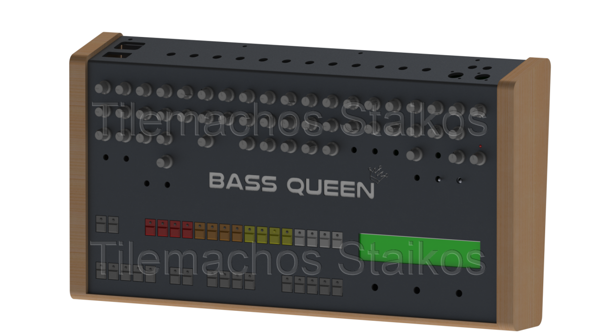
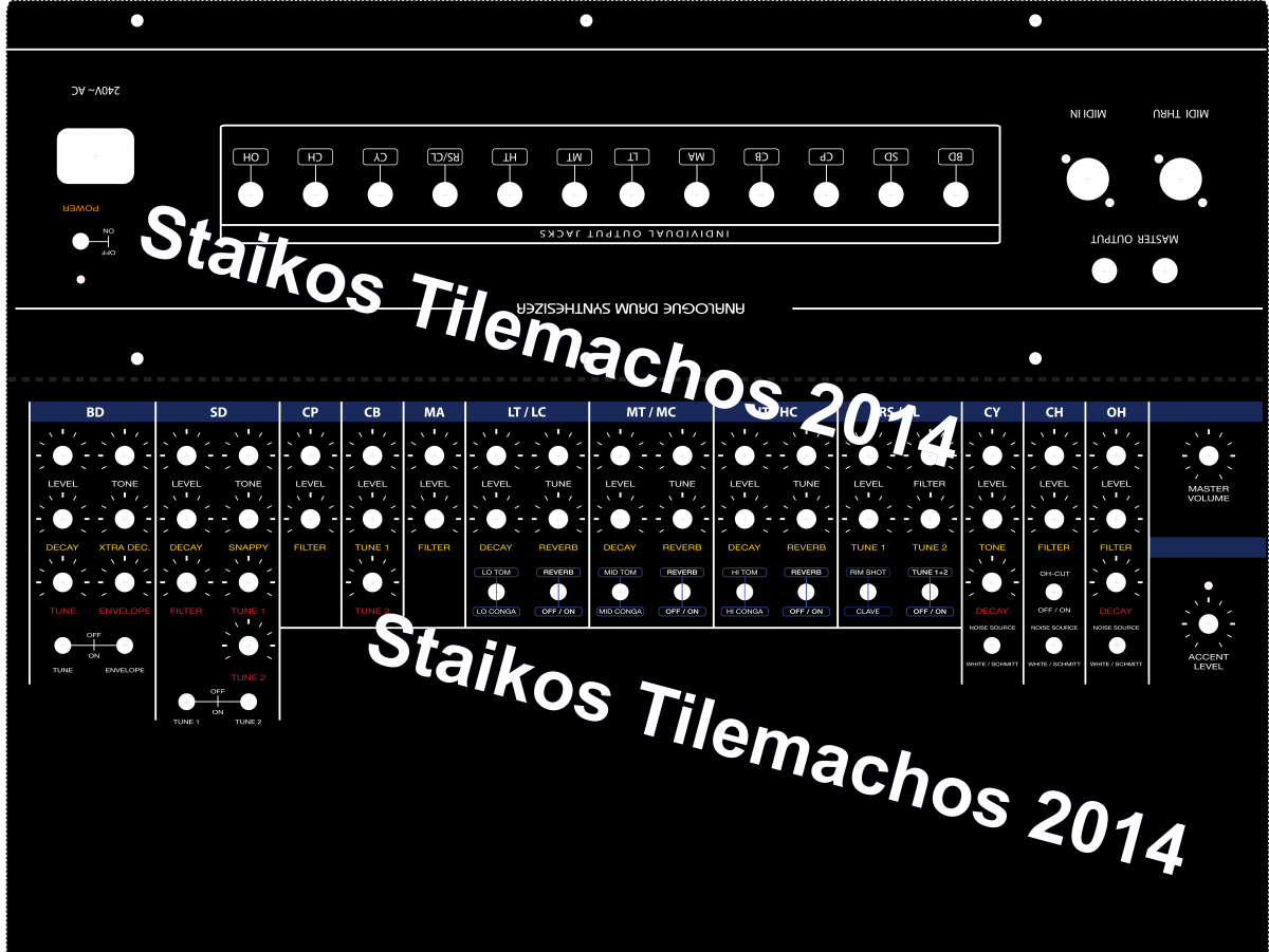
Thanks for your reply Thorsten First of all STM32F4 can support those lcd's.. i 'm just asking the pinning :) I'm making a clone of TR-808 and i wanna use your amazing Midibox Sequencer. I will not use the old MB808 seq... My design started from the begin and here is my concept : 1) TR-808 Voice Boards designed from the begin with SMD compoments wich means smaller and cheaper pcb. ( I have my own DIY SMD oven :D ) 2) Midi Interface wich means you can have different Accent(Velocity) for each instrument from a digital sequencer like midibox. 3) More voices than the original TR-808. ( I ll add Guiro and maybe some extra snare drums and also i am planning too add some 909 voices.) 4) Cymbal / Hi Hat / Hand Clap / Maracas / Snare Drum alternative noise inputs from front panel with patchcables. Alternatives sounds will be : Original Pink/White noise from 808 circuit or a 909 circuit or any other noise source,even a microphone. There will be many future adds that i am currently working on.. I want to use the midibox seqv4 but i wanna make a different version with GUI and real buttons. ( Midibox DR and MB seqv4 is not enough for me) I need to make a module that will help me make my dream come true and give some ideas so the midibox sequencer project go further. Here some pictures from my work on TR-808 voiceboard cloning in Altium Designer. Best Regards, Tilemachos.
-
Hello.. I am building a project based on the MBHP_CORE_STM32F4 I wanna add a 4.3" TFT LCD and the module i will use is this : http://www.4dsystems.com.au/product/4DLCD_FT843/ There is a 10 pin out from the screen. Here is the datasheet : http://www.4dsystems.com.au/productpages/4DLCD-FT843/downloads/FT843-4.3-Display_datasheet_R_1_2.pdf Here is the pin out : PIN SYMBOL 1 -------> 3.3V 2 -------> SCK 3 -------> MISO 4 -------> MOSI 5 -------> CS 6 -------> INT 7 -------> PD 8 -------> AUDIO_SHDN ----> Audio shut down ( dont know if i need it ) 9 -------> AUDIO_OUT ----> Audio Out ( dont know if i need it ) 10 -------> GND Any help on how too connect the pin out on the STM32F4Discovery pin out??
-
I am also building a module Based on original schematics from TR-808 with extra mods I ll post only my demo case It is not the final version.. There will be heavy mods on it I wanna use a DOG Display like MB9090 Any documents on how to connect it??