

Zam
-
Posts
625 -
Joined
-
Last visited
-
Days Won
26
Content Type
Profiles
Forums
Blogs
Gallery
Posts posted by Zam
-
-
Hello Thorsten
Tks for explanation
yes I'm on Mac, G5 10.3.8 running Digital performer, i'm not realy up-to-date regarding digital side of my studio...
I have a laptop whitebook running 10.6.8 for everything else including MIOS for setting up my fader proto
I have no clue on software programming an compilation...last "programming" was at school on PB15... 20 years ago :p
But I can learn!
Is your programme allowing adjustment for each fader, in something like a table or matrix, or is it a fixed value translating both way all pitch bend info ?
ZamI go to look google "how to compile" and i'm back :)
-
hey
here it is
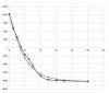
first graph:
X is dB reduction
Y is pitch bend value
red is the value read in MIOS according to DAW position fader
blue is the value read in MIOS when I position my fader at real analogue attenuation
I want the 2 curves to be the same :smile:
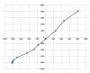
second graph:
X DAW fader pitch bend value
Y analogue fader pitch bend value
each point take for the same attenuation in dB (0-5-10-15-20-25-30-40-50-60-70-inf)
I want the line to be a straight one :smile:
-----------------------
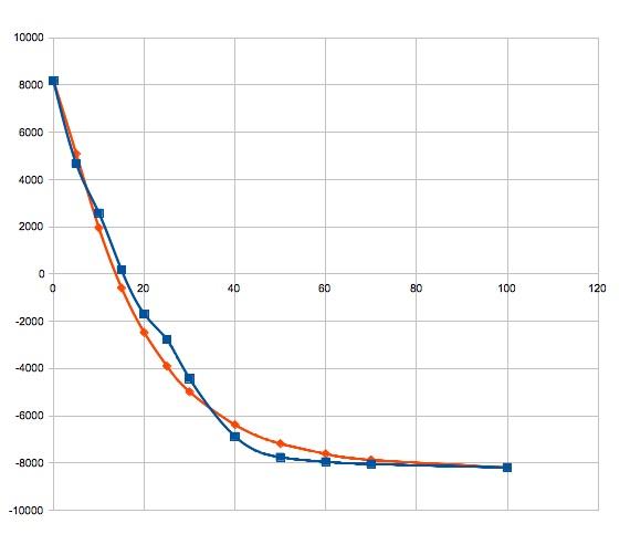
let take the example at 10dB attenuation (ref to full top position)
DAW send a PB value of 1252, but at this value the motor driver don't put my analogue fader at 10dB attenuation,
the fader need a PB value of 2576 to achieve this.
So, I need to translate value 1252 to 2576
at 20dB I need to translate -2480 to -1696 etc...
Zam
-
hello Novski
Off course I use the MF Tool !!!
I don't know how i can explain thins in other way :(
DAW fader log scale and analogue console log track are not the same log, and i need them to match.
The -18dBfs is a studio reference, nothing to do here.
The 0dB attenuation is always on the top of a resistor divider, but most of the manufacturer put a 0 ref label at -10dB attenuation and put a 10dB buffer after the fader so unity gain are not on top
what I need is a solution to convert DAW fader pitchbend value to another physical fader position on the MF_NG side
example:
pitchbend value 0 set the fader half way, 50mm from top in a 100mm fader.
But how can I do this 0 value put the fader 25mm from top?
I go to make some measurement and tab and i'm back :smile:
Zam
-
mmm... I have some read in the manual
did MAP command be a solution?
I also see the "curve" setup in the CV tool, i think it's something like that I need, but with a custom curve, that i can adjust...
-
Hello
First prototype is running, i will share pict soon
Lot of thing to check like motor electronic noise in my analogue audio path, i was able to reduce it with proper grounding, but still there when not touching the sense fader caps, anyway it's close to my Studer noise floor, should not be an issue as noise level is function of the fader position, and in real life if fader is up there is loud audio passing trough (min 60 dB over noise floor)
Second issue is mechanical noise, I'm not free regarding mechanical integration as i have to make the fader fit an existing frame/design, i have huge resonance in the frame and aluminium structure/pate, my first proto is not good i have to rethink the mechanic :) and maybe put some rubber/absorber somewhere, I use ALPS now, maybe it will be better with TKD fader
Also the regulator run HOT
Now some question!
Is it possible to rescale and change the response curve of the fader physical position?
The "problem" is that the DAW reading fader value don't match my real log audio response, it's not a problem when using a single fader, I don't care if I have offset or non matching boost/attenuation reading the value.
BUT if I group some fader the relative attenuation between audio channel is not linear
For example:
DAW side,
I have a kick on channel 1 at 0dB and a snare on channel 2 at -10dB that's 10 dB differential, both channel in same "drum" group
Now i move the kick 5 dB down given to me -5dB for kick, the snare fader follow and set the fader value at -15, relative power still matched, 10dB
On the analogue side,
Kick are initially at top pos (0dB) and move down to -2cm position (say it's a real attenuation of 8dB)
The snare are initially at -2cm position ( -8dB) and move to -4cm position giving 20 dB of attenuation.
My relative power change from 8dB (0-8) to 12 dB (8-20). My gain structure is broken and the snare is (relative) 4dB quieter
How can I manage that ?
Zam
PS: I start this project 2 month ago, and there will be a long time left before I solve everything, but I have to say your system is addictive and open a new world to me, THANKS !!!
-
tks Novski to pointing me at this, I will look better an learn MIOS
I ask this because i think i will print my physical fader automation in an aux send as i want to keep signal to the DAW mute/solo and main fader trough analogue output, then to each individual desk voices where my passive motorised audio fader is.
I don't need to implement physical button flip function, I will never flip, as I pass audio I don't want my fader to read or write another data
I attach my pic again, seem like it disappear in both post when I edit the double post...
I look at this Mec switches some days ago, and now I don't remember why I don't try it in my design :question:
Zam
-
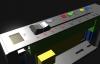
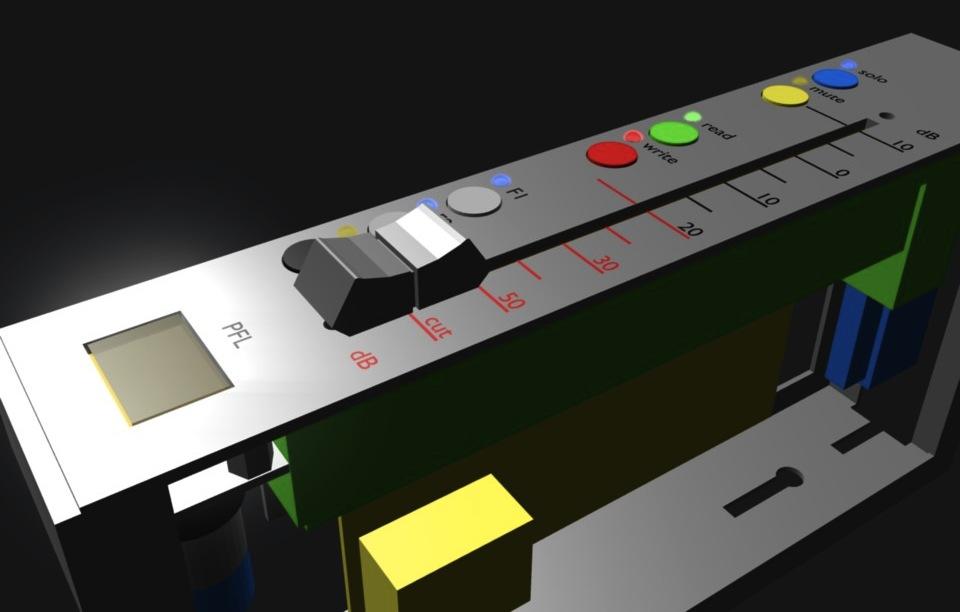
hello
Here is a preview of my "moving fader !
Anyway 3D rendering is just for fun, it's more to see how to put all i want in my existing frame modules
I'm already waiting for my MF board to perform the first test
I'm little disappointed about switches i find, there is so nice illuminated NKK or Omron, but none of them have pinout compatible with 2.5 or 2.54 pitch
For the moment the candidate are round ITT schadow with separated LED, and i keep the original illuminated EAO for the PFL
I have question regarding HUI or MCU mode with the MF_NG, is it possible to "flip" the destination (aux send for example) form MIOS?
Zam
-
mmm... double post :rofl:
-
Hoooooo !!!!
Tks Peter! didn't see this, my order is in process :happy:
Zam
-
Ok :happy:
-
Hey all
I order MF_NG and a PIC from Smash TV 10 days ago, I read about possible delay, no problem at all
I'm just wondering if it's normal I don't receive any confirmation email about my order ?
Zam
-
you want to light both LED at same time with fast pulse ?
I just ask because you will have yellow colour :rolleyes:
-
Is your VCA driven by a different Voltage range then the 0-5V of the MF_NG Module? I don't really understand why you need a dual Linear Track...
hey Novsky
actually my VCA (studer modular card around DBX/THAT) are set to 1V/40dB and are drived by a DC coupled soundcard in the +1/-2,5V range to achieve +40/-100 dB of gain.
If I want a moving fader (automated by DAW with HUI) I need one servo track, the other track will be the one driving the CV input of the VCA.
I not sure using the same DC signal for both function will be a good thing ? even if I do a converter/offset circuit from 0/-5 to +1/-2,5V (or +4/-10v, i have different CV sensitivities jumper)
But maybe it's something to try :)
Anyway the main goal is to keep the signal passive, that's the first thing I want to test.
VCA stay in my mind just because of my stereo channel, and accuracy i will find (or not) by using two audio fader.
TKD offer me stereo audio track + servo and touch, but I'm not sure it is in stock now.
Zam
-
Yes, the MF NG can run stand-alone. Take a look at the module's description!
Tks ilmenator, I already read this, but need a confirmation.
ALPS dual track (lin+log) are on the way.
If some one have an idea where to find dual linear track (servo+VCA) ? i don't find yet...
Zam
-
Hello
I have a dumb question...
Are the MF_NG modules able to work "stand-alone" or do I need a core system in any case?
Zam
-
Keep the cables as short as possible, I wouldn't expect this to work for cables longer than 1m.
yes...have to test, not an easy mechanical integration, I have room in the fader modules to put new fader and led/button, but not easy to leave pcb close to the front (fader) of the 8 unit subframe (5 in total), at best i can dispatch on the back of the console.
Zam
-
Hey NovskiHi ZamThats a huge Projekt you are planing here.
I am developing modules for a DAW remote that may look similar, but without Audio. I have some pre built modules from smashTV (midibox-shop.com) that i dont need anymore because i built my own. PM me if you whant pre built ones...
Best regards
Novski
Tks for reply
When you say pre built you mean already soldered? I may be interested, depending of your price. Let me know :)
Are the firmware already printed? I just have to install the OS?
The advantage of the kit is that i don't have to pay soldering job, and I also have just component I need and extra connector and ribbon in low quantities, Otherwise I have to order component in larger quantities (mostly on RS for me), for the prototype i don't need to many.
Your version is the pictures above on this page? You change the connector layout to have single ribbon with servo and touch for each fader?
I soon made a list of what I have to test.
for example what is the max length of ribbon between PCB and fader without losing data, my console frame is "large" and final project (if possible) will have all card in a 19" rack.
Zam
-
Hello
I'm new here, some pple on groupdiy point me on this forum regarding automated fader
I have a look at the main website, also here in the forum. I think i find the correct place :happy:
My "project" is basically to replace my diy patchable VCA automation on my hold discrete mixing desk.
I have a long read and I understand that all the ppl prototyping/building controller around the MF board set it up with servo track fader only (for DAW control)
My goal is tu use dual track (log audio+lin servo) to perform a passive audio automated fader, like "flying fader", "moving fader system" or more recent API 1608 and neve "swift mix" in the 5088.
I find ALPS RSA0 series with servo and audio track that will be good for prototype as your guys already use this series with success right?
I don't find K series yet or P&G8000 with dual track, but if someone have input? i want to test different hi qualities fader. RSA0 are "low cost" and audio spec are not optimal for my use especially the audio taper tolerance.
I want to buy a MF_NG kit, i saw them in America trough midibox-shop, nothing in EU for this?
For what I understand i need to print firmware to the PIC, i'm not able to do it, so I have to ask when I buy it, I just have no idea about "PIC ID header" I need. After that I can access all other setup/calibration via MIDI with MIOS right? I don't understand everything about software right now but will learn.
MF_NG work in stand alone right? in need nothing more for prototype (except PSU)
Enough question for the moment, i just let you know my final goal
32 motor fader controlled by DAW fader
32 rec automation push button + 32 led status
32 play automation push button + 32 led status
32 automation mode select push button with led status (have to define how many mode i need...)
32 relay paralleling my mute switch (actually driving a FET post fader)
If possible with more core system there will be 12 more fader pack (44 total) for master and aux return
I'm not talking about mechanical integration but I want to keep it modular, as the console is. By the way it's a 70' Studer 289
Tks in advance.
The system your developing is so exciting :hyper:
Zam

Upcoming MBHP_MF_NG module
in MIDIbox HUIs
Posted
hello Thorsten
I have to admit I'm little lost with this, but in the mean time I think I understand what you say.
When you say flash memory you mean the SD card with core system (for the moment I only run MF board standalone), or some memory available in the PIC I have now?
I think 10bit is enough for motor position, it's less than 1/10mm for 100mm fader, my hand never do such repositioning when I recall a mix to the desk :smile:
So your option is a fixed table, but previously set for each fader log characteristic according to measurement i made like previously in this topic, right?
So each time i want to recalibrate the fader (saying with time the resistive track characteristic change) I have to do measurement again, and compile new table for each fader?
How it will be complicated to add a new function in the MF tool (like a new tag or window) with a matrix or table where you can set the value for 12 point (0-5-10-15-20-25-30-40-50-60-70-inf).
The table have only to be adjusted at one side. The fader position pitchbend value in the DAW will never change, except if different DAW have different log curve for the fader?
Or better, a learn command! when you clic, it record the motor fader position in the table, so a routine calibration (say each month) take less than 10 min
Just send a test tone in all channel
set all fader at top--> one clic--> all "0dB" data are stored (usually 1023)
set all fader at -5 (real dB analogue attenuation read at my peak meter)--> one clic--> all "-5dB" data stored
set all fader at -10 etc...
maybe I'm dreaming ?
by the way I attach 2 pict of my work :smile:
second prototype have button and led, but it's just for mechanical test.
Also need nice front panel...
Best
Zam