gotkovsky
-
Posts
43 -
Joined
-
Last visited
-
Days Won
4
Content Type
Profiles
Forums
Blogs
Gallery
Everything posted by gotkovsky
-
Thanks, will definitely do it! Have a nice week-end, K
-
Damn, you're right, I missed that part from the tutorial, not sure what happened… thank you so much for taking some time to help!
-
Sorry about that, just edited my post! Yes, I tried to reflow all of them, checked for shorts or anything else but I'm still having the same issues.
-
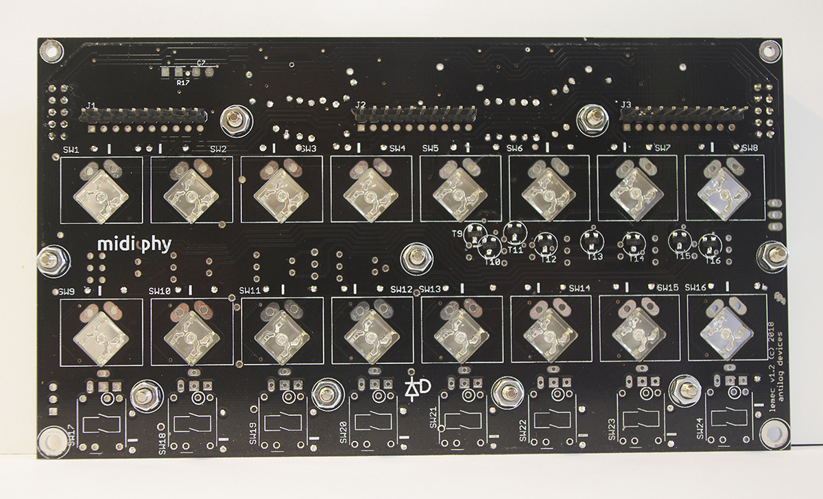
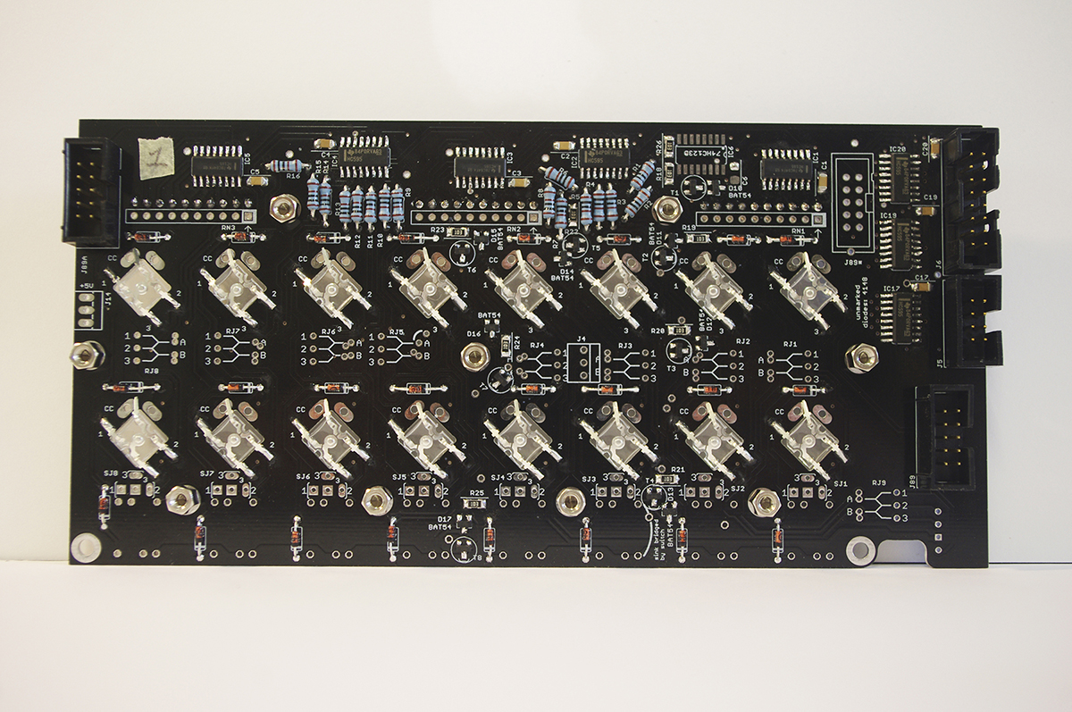
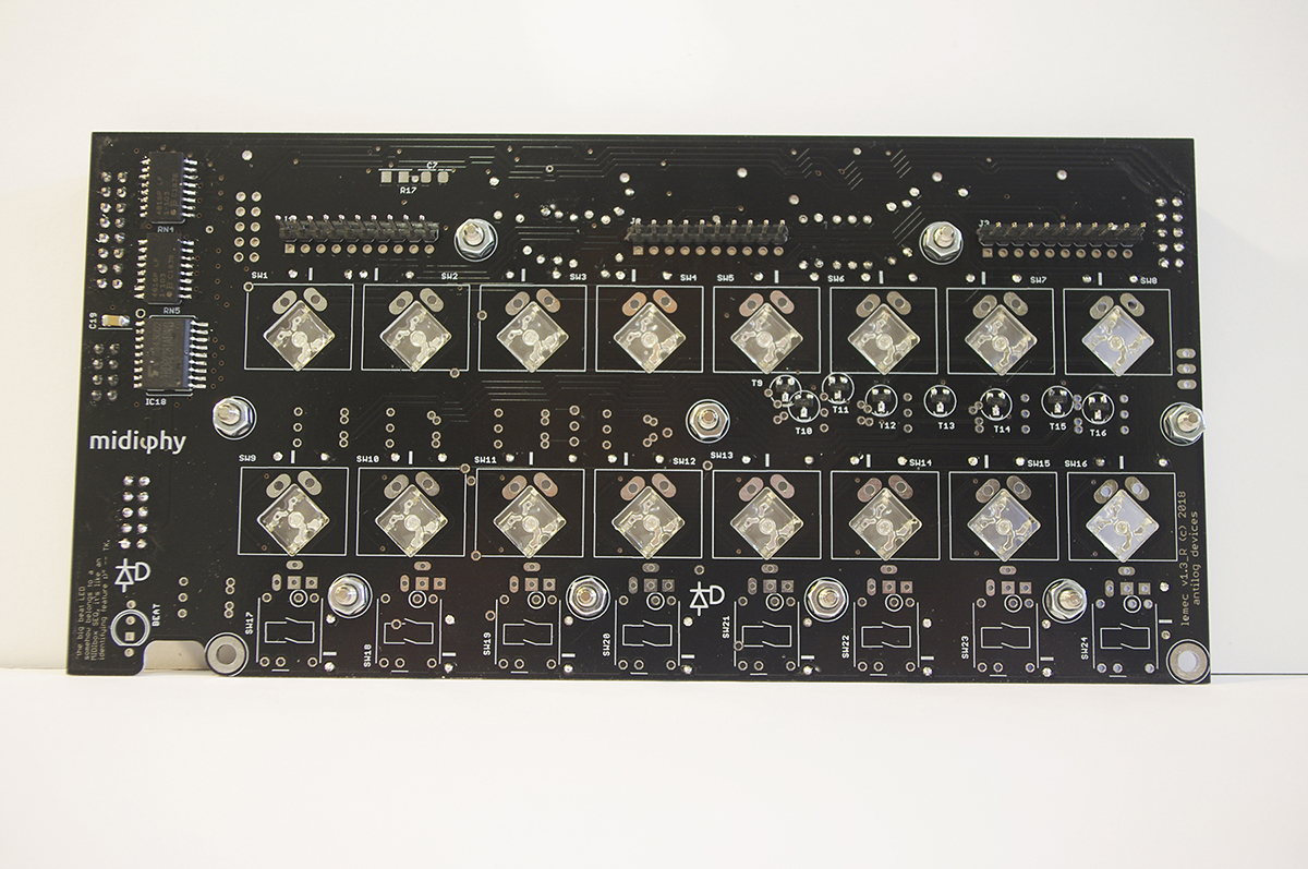
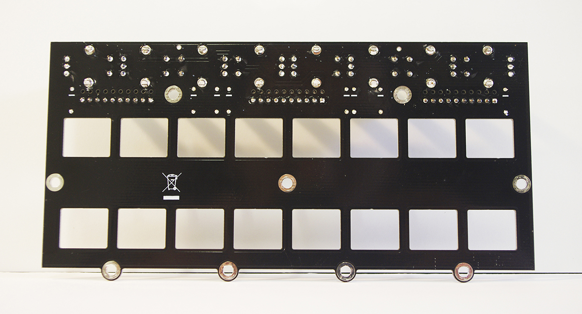
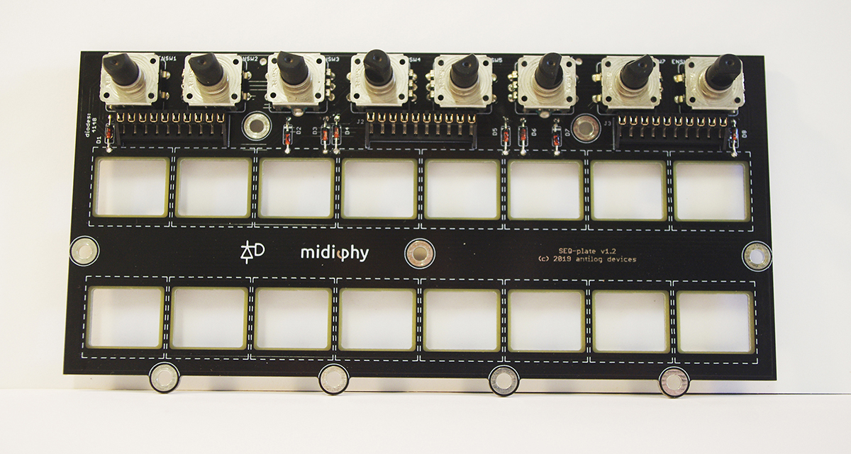
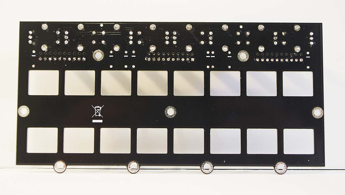
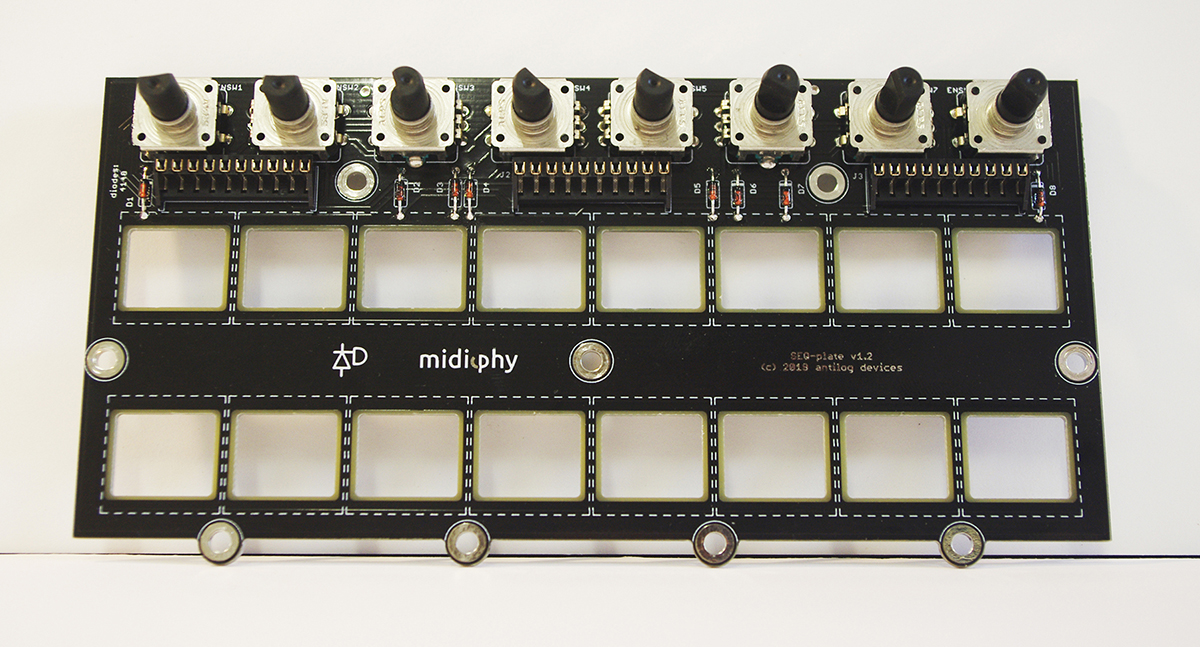
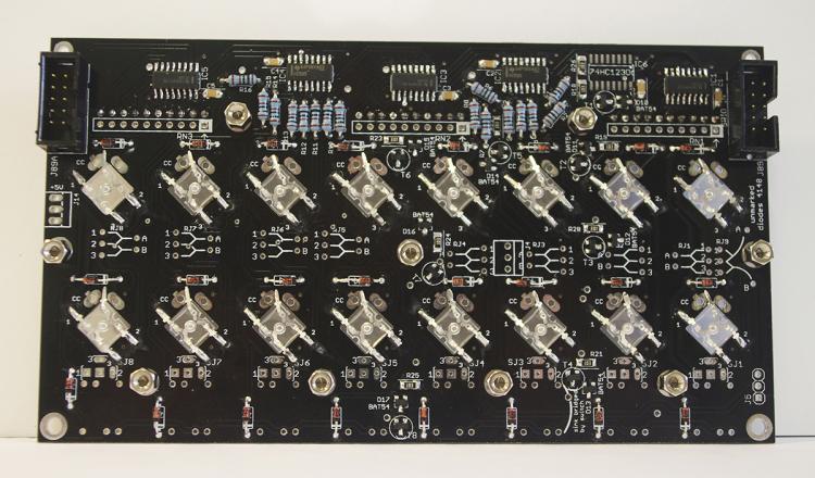
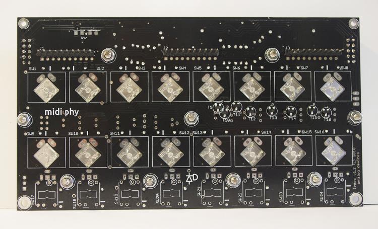
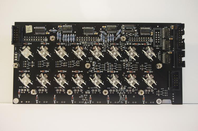
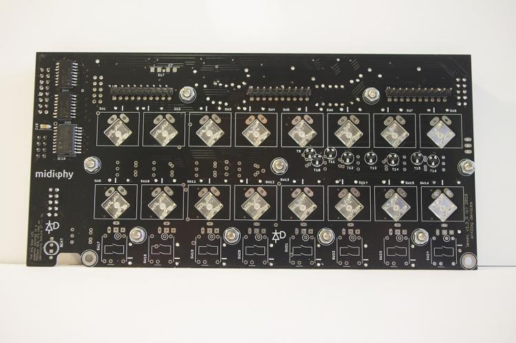
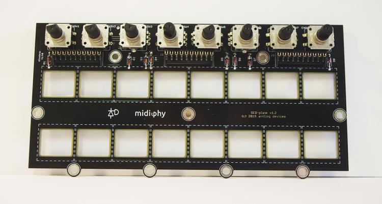
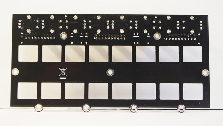
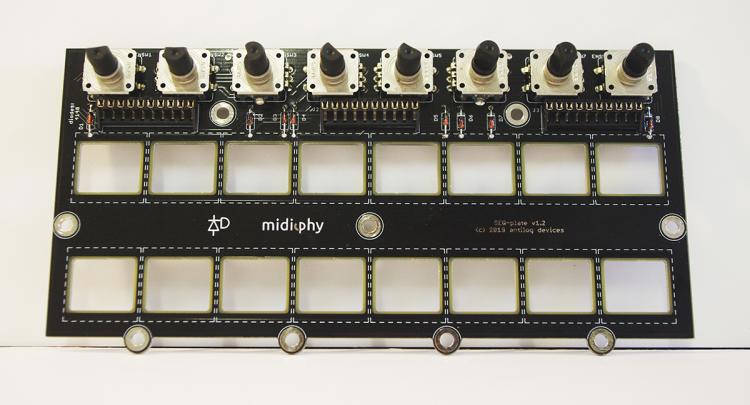
Hello! I just had weird issues testing LeMec PCBs. Basically, as soon as I ‘set debug on’, MIOS Studio detects erratic button actions, as pasted here: [84691.903] [MBNG_LCD] no response from CLCD #1.1 [84691.903] [MBNG_LCD] no response from CLCD #2.1 [84691.904] [MBNG_FILE_C] Event Pool Number of Items: 348 [84691.904] [MBNG_FILE_C] Event Pool Allocation: 12250 of 65536 bytes (18%) [84691.924] Patch 'seq_l' loaded from SD Card! [84691.932] [MBNG_FILE_R] /seq_l.NGR (optional run script) not found [84741.581] set debug on [84741.584] Debug mode turned on [84741.586] MBNG_DIN_NotifyToggle(69, 0) [84741.586] No event assigned to BUTTON hw_id=69 [84741.598] MBNG_DIN_NotifyToggle(69, 0) [84741.598] No event assigned to BUTTON hw_id=69 [84741.608] MBNG_DIN_NotifyToggle(69, 1) [84741.608] No event assigned to BUTTON hw_id=69 [84741.618] MBNG_DIN_NotifyToggle(69, 0) [84741.618] No event assigned to BUTTON hw_id=69 [84741.629] MBNG_DIN_NotifyToggle(69, 1) [84741.629] No event assigned to BUTTON hw_id=69 [84741.639] MBNG_DIN_NotifyToggle(69, 0) [84741.639] No event assigned to BUTTON hw_id=69 [84741.651] MBNG_DIN_NotifyToggle(69, 0) [84741.651] No event assigned to BUTTON hw_id=69 [84741.661] MBNG_DIN_NotifyToggle(69, 1) [84741.661] No event assigned to BUTTON hw_id=69 [84741.671] MBNG_DIN_NotifyToggle(69, 0) [84741.671] No event assigned to BUTTON hw_id=69 [84741.682] MBNG_DIN_NotifyToggle(69, 1) [84741.682] No event assigned to BUTTON hw_id=69 I didn't include everything as the data flow seems infinite, sorry for the long scroll, I don't know how to make this as expandable text. So I took apart the PCBs, inspected everything, reflowed all the joints, but that didn't change anything. Should also say that JA PCB works fine and has been tested as shown in Peter's video tutorial. Here's links to hi-res pictures of the PCBs: https://imgur.com/6pDz8Hr https://imgur.com/K9tGJiE https://imgur.com/4AysPiy https://imgur.com/HFG2OFQ https://imgur.com/nNya3EN https://imgur.com/cYjZHBN https://imgur.com/i7sBJC6 https://imgur.com/v05FspA Does someone has any ideas of what could be wrong? Hope someone can help because I'm stuck — once again :) Thanks in advance!

-
Ok, the headers were just not pushed enough, I just gave it a good push and now everything works fine… not the first time that I feel like the dumbest dude on planet earth on this project ;) I'm surprised about how much force we need to apply on those so-small pieces sometimes. Anyway, thanks latigid on and Peter for the super fast replies as usual, you guys are the best. Wish you a great day (as sunny as mine in France) K
-
Yes, no other options than << none >> on the dropdown menu. I also tried with the micro USB, the Waveshare is still powered (VBUS is lit) but doesn't show up.
-
Hello! I'm almost done building all the PCBs, and I'm having another issue uploading MBSEQ App on the Waveshare, just searched a few hours on the forum but couldn't find an answer. So I got MIOS Studio 2.4.8 running (on MBP High Sierra), but the MIOS32 midi I/Os don't show up on MIOS Studio (just displays << none >>). I tried several options but nothing worked so far (tried booting different versions of MIOS Studio, restarting MIOS Studio or PC several times, MIOS Studio on another Macbook running Mavericks too). Here's all the infos I could gather: —Red PWR led on the Waveshare is lit. —VBUS led on the Waveshare is not lit. —Checked the soldering on all PCBs and nothing looks wrong. —Waveshare's pinheaders are not fully engaged on low-profile headers (but I can't seem to push them further). I'd greatly appreciate a bit of help is anyone has a clue, thanks in advance!
-
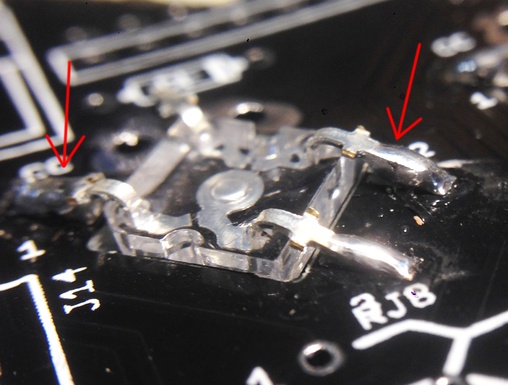
Yes, I've been very careful about no heating the LEDS, and set my iron to 300°C as suggested. I just had to desolder one superflux LED at some point, I then verified it with a CR battery and it still worked, so I resoldered it to the board, and by trying to reposition it flat, I lifted two pads.
-
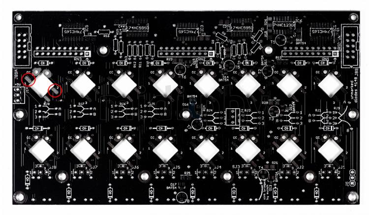
Good morning everyone, I made a soldering newbie mistake once again… let's hope it will be the last one. So working on a LeMEC board, when adjusting the position of one of the superflux LEDs, I managed to lift the pads 1 and 2 of SW8 (see pictures attached). These two pads are not completely ripped-off but definitely lifted, so I'm not sure if they provide a good connection. I should also say that a LED is still soldered on SW8 spot. Is there a way to verify the connection between pads 1 and 2 of SW8 with the soldered LED? Or soldering a wire bridge to another point on the board? Hope someone can help again, thanks in advance!

-
Cool idea, but I also think that the led windows are way too small, sorry… I'm almost sure that I'll paint the caps in white, inside and outside if I can, leaving the top unpainted, and will post the results here (probably next week).
-
I'm currrently building a V4+ and also thinking about painting the external sides of the DSA keycaps (probably in white to match the case, which should block the light sufficiently). I think it would provide a clearer indication for the eye, and shouldn't be difficult with some spraypaint, varnish and good masking tape application. Painting the internal sides is not a good idea IHMO, as applying tape inside the caps would be almost impossible to do accurately. Or maybe painting the inside in black with a small brush, and the outside with white spraypaint?
-
Great, thank you for taking some time to help me, and also for calming my nerves!
-
Hello again, As written just above, I had problems with pinheaders, soldered in the wrong directions, which I managed to desolder without damaging too much the board or other components, at least visually. So now I'm a bit anxious because I don't have the skills to know how to verify that every other component on the board is still ok or has been overheated, which I guess would cause future problems. Is there ways to check that other components are still ok or need to be replaced? I spent hours (!) to desolder the pinheaders, being careful not to heat the board too much or stripping the leads, but it's probably way too much time (I obviously took breaks but still… ). Am I being to nervous here? or should I just re-order a new wCore PCB and the corresponding parts, since it wouldn't cost so much? PS: I'm definitely thinking about creating a thread dedicated to my build, so I wouldn't flood this topic with newbie questions, and I'm sure it would help other noob midiboxers just like me, who are willing to learn on the job. Thanks in advance!
-
Thanks for your advices! It took quite some time but I managed to desolder all the pinheaders, by lifting the plastic parts and desolder the pins one at a time, as suggested. Even with desoldering one pin at a time, it was a lot more tedious that I thought, now I just hope I didn't damage the board too much and that the rest of the build is gonna go fine :) @latigid on I meant normal unshrouded pinheaders (Hawkeye refers to them as ‘gold pinheaders’ in the V4+ build tutorial).
-
Hello dear midiboxers! I'm building a V4+, and just had my first screw-up… I managed to solder in the wrong directions the gold pinheaders of the wCORE. And of course realized that after having soldered 8 of them. I tried to desolder them, using desoldering braid and pump but had no luck so far… so I was wondering what would be the best option between clipping off all the pinheaders and just reinstall new ones (I guess removing the solder without the headers in the way would be easier ), or keep trying to desolder and therefore take the risk to overheat the board? Would love to have your opinion, thanks!
-
Ok, thank you CJ55 and latigid on for your precise answers!
-
Thank you latigid on and gbrandt for your answers! Sorry about that, I'm a complete newbie and a bit afraid to order the wrong part, so just to be sure, could you give me a link of a specific component that could replace CR1206-JW-561ELF? I couldn't find a 500 or 470ohm CR1206 on Mouser, just 430 or 510. Is this one ok? Or that one? They're not the same dimensions as the Bourn's, which is why I'm asking… And I'll check Reichelt for sure! Thanks
-
Hi everyone, First post here, oh my :) After a few months of saving, I just bought a SEQ V4+ on the awesome Midiphy Shop, and can't wait to get my hands on it. It looks like the sequencer I've been searching for a long time! The Midibox community is so interesting and impelling to me, thanks everyone who in some way or another has contributed to the SEQ project. So I ordered all the components from Mouser for the V4+, and I just got an email announcing that a few parts were out of stock. Here's the list: 1 • CR1206-JW-103ELF (10K resistors) 2 • 3FTH9 (MEC switches) 3 • 1S11-19.0 (MEC switch caps) 4 • CR1206-JW-561ELF (560ohm thick film resistor) I found 1, 2 and 3 on Digikey and RS-components (I'm located in France), here are the links while I'm at it and if that can help: Digikey: 1, 2, 3 RS-components: 1, 2, 3 Digikey seems like the best option since you can order in single quantities. It was quite easy to find the missing components apart from number 4, which is out of stock everywhere. So, sorry if that's a silly question, but I was wondering if anyone could help to find some alternate component that would replace CR1206-JW-561ELF? Preferably on Digikey, since all other missing pieces are available there, but somewhere else would be fine too. Thanks!