niles
-
Posts
56 -
Joined
-
Last visited
-
Days Won
4
Content Type
Profiles
Forums
Blogs
Gallery
Everything posted by niles
-
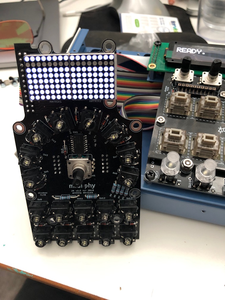
Latigid on and Hawkeye - THANK YOU! It's up and running! (one caveat below...) Sorted out my JA board issues and it's firing a basic sequence now. The OLED displays are amazingly crisp and clear. This box is a thing of beauty, really quite a nice piece of engineering and design. I am looking forward to learning it. Thank you for offering it as a kit! One caveat, though (there's always one in my world), is that I'm getting weird output from the 4 main Midi out ports. To test it I'm running a simple sequence with one note and one default gate length, and my synth gets the note (a behringer neutron) but only once ever, and it's like an infinite gate. Happens with all 4 of the Midi out ports. The IIC ports all work great when I change the midi output port on the fly while the same sequence is still running. The IIC ports appear to be operating normally so I'm thinking it's an issue with the midi8 board. Before I tear it apart and examine the midi8 pcb, I just wanted to confirm that there's no global setting or something that I need to enable or set for midi8 board? I'm guessing no but hey just double checking. If I do need to debug midi data, is there a recommended method or test sequence I should run against a known good port? Should I use mios studio or midi-ox or probably doesn't matter? Thanks again
-
Just reporting back in quick - it was the cable. I guess practice makes perfect, now the led matrix works perfectly. Getting there :)
-
@SimonSays Please keep us updated since I also ordered the PCBs from modular addict awhile back. I'm hopefully finishing up my seq v4+ build soon and will tackle a 6582 build soon after. Got a small bonus at work and splurged on a slew of 8580 chips from meeblip a few months ago in preparation, also. I guess they are sold out now. Have you turned up any ideas for the display? The hot thing is OLEDs now and some people get them to work it appears, though I haven't found a real guide.
-
Thanks - I think it's the cable. I have continuity everywhere but from J5 pin 8-> cable-> j2 pin8. Will replace that once I get new ends - I think I wore out the 24pin header.
-
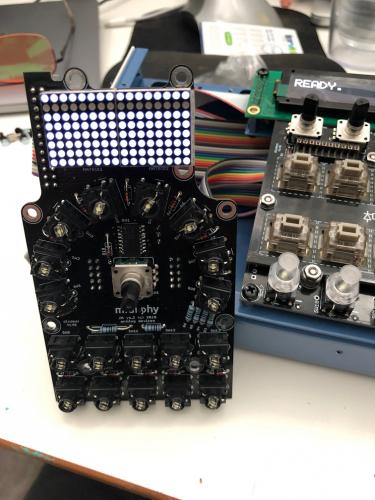
Hi - I had some more time today to make some really good progress. So far everything is going smooth except for the JA board. I have the case almost all the way together. for the JA, I'm going to debug the weird button behavior I had way back, now that I know how the ICs work a little more. Anyway do you know what would cause this row not to light in the matrix (please see photo below)? The 2nd row of 16 leds aren't lighting on the JA matrix. I've reflowed the matrix pins and the large 24pin connector, as well as the respective connectors on lemec_r. I am guessing this matrix doesn't connect to anything else on the JA board that would cause just this row to not light? Thanks
-
Makes sense, I suppose it would want to go as fast as possible for quick registering. Is the RC = reset clock? Still not seeing any action on switches. I did for a little time right after I reflowed the ICs I mentioned but now nothing is showing up in MIOS. I'll test all the pins again with the scope and report back and basically go back through your previous posts on this thread. I still get perfect encoder twisting registering in MIOS studio, just no switches.
-
Initially I wasn't seeing anything on pin 14 on IC20, so I reflowed 17, 19, 20 pins and now I do see something. I do see normal (I think) behavior on IC2 now. I am curious what the CLK signal should be, though. You mentioned 1khz. I'm reading a little over 667khz on all clks, including the left le mec board. Thinking it was user error, I tried my function generator with a 10khz square wave the scope read it perfectly with no adjustments. I am wondering if perhaps it's just getting clk'd too fast to really give reliable operations? What controls the frequency signal?
-
I believe it is, what is the side of R26 connected to? I see the end closest to the pcb edge is to pin 8 of IC2. I thought I could test resistance between pin 8 and the mystery point just to be sure R26 is soldered on there correctly. Turns out there is no pulse train on Pin 14 on the R board. I see it clearly on the L board, it does help that one board works to compare! Do you think this IC2 is just a dud or perhaps damaged somehow? I get 0V on pin 13, also.
-
I tested it this way and saw only one note at a time when I bridged those 165 pins to 0V. Also I see the same behavior with the seq-plate removed so I don't think it's a clearance issue. On the L board, I see a sequence of 1 square wave that drops to 0V, and holding down 2 switches I see 2 square wave seqments drop to 0V so I assume that is all good. On the R board, there is no sequence(?sorry I don't know the correct term) drop to 0V, it's the whole thing, just all flat to 0V. Same with the other columns on the R board. I checked, no shorts between pins on ICs. With seq_r loaded, on the Left board, on the scope I see a sequence on each of the output pins of IC2, although I can't seem to see any activity even if I press the switches. They just seem static although that could be my inexperience. I mean, the Left board switches still register in MIOS studio console so it's prob me :) On the Right board however, each of the outputs of IC2 are reading high, no sequence. That would probably make sense that IC3 has all the high readings, then, right? If it depends on the outputs of IC2 being correct sequence? Both chips have clock in, it appears. Hopefully I'm still moving in a forward direction with this!
-
Well for each button pressed it's the same each time. I get different groups of 4 registered in the debug screen on each encoder. Now I can't get any of them to register, unfortunately, after a good cleaning. Encoder twists still register great. COnfirmed I have seq_r.ngc loaded. I started comparing lemec L and R, and on IC1 on the L board, I don't see any voltage on pin 4 and 6, although I do on the R board. My L board is working fine (switches/encoders that is), should pin 4 and 6 read +5V as on the R board IC1? IC1 is right next to the J89 connector on the Left board, so wasn't sure if maybe that is relevant to my problem. I'll continue comparing the IC voltages via my scope but just curious which ones should be the same between L and R. All of them? Thank you
-
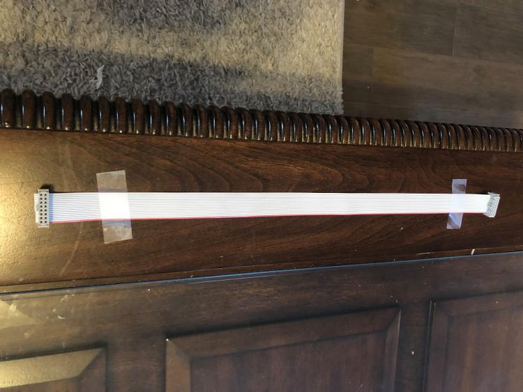
pretty sure everything is correct, I can make another cable (third one...) and see if that makes a difference. In the meantime here are photos.

-
I get a similar output each time I press any of the encoders on the right lemec board, not just the ENSW8. I don't see anything touching, and I see the same behavior if I swap seq-plates from the left lemec board. As for SW19, when I temporarily install all the switches in the lower row, each switch registers similar 'quadruple' output messages as the encoders. Same thing happens if I test SW1->16 as Peter shows in the video with a small, horseshoe shaped length of wire. I reflowed some points and all the diodes, still no luck, unfortunately. Given that it's happening to all switches, would there be a point somewhere that would affect all of them somehow? Also I don't have the JA board connected past the right lemec so not sure if that is affecting things?
-
@SimonSaysWow great job! I am getting there bit by bit myself. I am at the DIN switch test phase, I have the lemec boards plugged in and since I hosed my JA board I have the Left lemec plugged into the core and running seq_r instead. The left board is checking out good so far. The right lemec's encoders register normal when I twist them, but pressing them as a switch registers 4 events. All the switches on the right board register as 4 different switches, I assume the ones in their little matrix. The bottom 4 (SW17, 18, 19,20) do not register at all. Any idea what this could be? Sample output when I press ENSW8 on right lemec: [130673.482] 90 4b 7f Chn# 1 Note On D#4 Vel:127 [130673.495] 91 63 7f Chn# 2 Note On D#6 Vel:127 [130673.500] 90 63 7f Chn# 1 Note On D#6 Vel:127 [130673.515] 90 33 7f Chn# 1 Note On D#2 Vel:127 [130673.618] 91 63 00 Chn# 2 Note Off D#6 (optimized) [130673.622] 90 4b 00 Chn# 1 Note Off D#4 (optimized) [130673.636] 90 33 00 Chn# 1 Note Off D#2 (optimized) [130673.640] 90 63 00 Chn# 1 Note Off D#6 (optimized) Thanks
-
Thanks!
-
@latigid on Hi I'm at the point of testing the lemec boards, and if you recall I have some issues with the JA board. As you suggested earlier if the power is ok, at least some of the board should work. I just want to make sure power is ok passing through the board, could you let me know what the voltages should be on the pins for SRIO out? Or point me to a link with it, I can't seem to find it via search. Thank you! Nevermind I forgot I can use seq_r to just chain it the other way around. I'll figure out the JA board later. Thanks though
-
Will do. That makes sense with _L vs _R chaining order...I'm going to give your suggestions a shot, the piano roll on midi channel 3 with seq_l.ngc loaded and the chaining test. will report back once I have something. And as always, thank you for the thorough reply!
-
Yes-I replaced RN1. When I say I hold my hand on the back I mean that it's just very sensitive to touch. It's not like that with the other switches, just sw2,7,9,11,12,13 - they all act like one switch, one led. The only ones that are working as intended are sw3,4,5,6. The rest are dead switch/dead led. I usually solder THT components from the bottom out of habit. Attached a picture below of back. using MIOS studio as you suggested, I get some LEDs to light up. I can't follow which DOUT 1-7 and DOUT 10-15 correspond to which LED, it seems random. I tried reading the http://ucapps.de/midibox_ng_manual_ngc.html page about LEDs so I see that different combinations=different patterns, though unclear if that applies to this or the little matrix on the top of the board. Don't suppose there is a test script that would light up LEDs in sequence? One question I have is how does the chaining work with J89 and J89A? I see I have to connect the Left Lemec board into J89A on the JA board, would I be able to test the lemec boards if I just plugged the left board directly into the J8/9 on the core board? I am not sure if they are a direct connection or somehow buffered/filtered through the JA board first. I ask this because I just want to move ahead at this point (and see what else I screw up lol) and some of the pins aren't connected between J89 and J89A, which could be normal or not.

-
Well I replaced all the ICs on the JA board and the problem is less but still there. Now if I hold my finger on some of the pads on the back, the leds light up. I tried my other waveshare board and it's the same behavior. Attached a picture. Maybe I just order a new PCB and the specialized parts. Fingers crossed I didn't damage the main uCore board

-
Ah ha - I must have just seen the '4816P' and so grabbed the bag with the wrong one. I installed the 1-103 in that location not the 2-103. I'll make that switch, hopefully I can salvage the one from the board, looks like I need it later on. Thank you again, I'll give this a shot and report back.
-
Quick followup on my SD Card not reading problem - Success! I was able to get the SD card to work :) It was something with the core board. No idea what it could be and not spending anymore time fixing it. Just redid the boards using new PCBs. The MCU was fine after all so now I have an extra for future projects. However....- I hooked up the JA board and loaded 'seq_l' program successfully in MIOS studio. However the LEDs and button activations are going haywire. I realized with slight horror that I used an older cable that I had made that was basically backwards. I have some extra HC595's from original mouser shipment and replaced the IC1 (directly under the SRIO IN shrouded header), but still getting the crazy led action. Good news is all the LEDs are lighting up and they are registering on MIOS studio, the encoder is as well. Bad news is they are just randomly flashing and activating on their own. Is there a schematic or pinout for this board so I know what I may damaged with incorrect cable? Could a bad cable have damaged the RN1, IC2 or IC3? Thanks!
-
Hi - very new to the forums and building a kit for the seq v4+, I have received some great help from Andy and Peter over on the seq v4+ troubleshooting thread but I have a more general SD card handling question. Background: I'm having a hard time getting the SD card to be 'found' so I can load a test program, and have not had success at all with that. Just keeps saying SD card not found. I've tried many variations of cards, my latest is a brand new 4GB sandisk SDHC microsd with adapter formatted FAT32. I have NG 1.036 installed and everything seems to be good so far...MIOS studio recognizes it no problem but just no SD card is found. I can confirm the cable is fine, no shorts between pins, I have continuity from card socket (a SD-RSMT-2-MQ) to the MCU board and even tried the 'simple SD card cable' from TK's website. Nothing so far has worked getting the SD card found. I'm on Win10 but same happens on Mac laptop. I think I had the cable backwards the first time on power up but I don't see how that could have fried anything, besides it still runs in MIOS studio. How does the SD card get detected in the STM32F4? Is it the mechanical switch on the side where the 'write protect' and 'card insert detection' are both tied to ground? Or is it one of the pins like CS? (I've read there are a few ways possible).CS (SD socket pin 1, J16 pin 10, RC1) is tied to GND. Is that right? Is there any type of way to 'fake' SD card detected because maybe it can read/write it ok but thinks it's not in there? Or perhaps a MIOS studio diagnostic? I see there is some commands via the 'help' command but not sure if any apply to SD card testing. I appreciate any insight anyone has into this, Thank you!
-
Well there's no shorts and I don't know what to do with that schematic anyway. I've built plenty of synth-related items but none that rely on SD cards. I'm at a total loss. It's too bad there's no way to just run some kind of diagnostic program that would tell me there's no input or output received or something. I don't know enough about how this MIOS studio works to debug errors.
-
quick question related to the pins. I am trying to trace shorts even further and RC1 (pin 10 on the J16), which goes to CS/SS (Pin 1 on SD socket). It's is the PB2 also called "BOOT1" on the MCU board. Disconnecting the MCU board it's shorted to ground, is that intended or accidental short? Thanks I fear I may just have to shell out for a new MCU board, not sure what else to try. Perhaps I can use the original board in another Midibox project in the future without an SD card lol.
-
I checked continuity and everything seems fine. The cable is something I did have wrong at first, so perhaps I fried a MCU pin or two. Is there a diagnostic program or command I could run in MIOS Studio that would confirm the pins are 100%? I'm using shrouded cable sockets and they are oriented correctly I think (please see photos though). I did order a few more SD sockets (arrow has free one day shipping today :) so I'll replace that just in case. It was simple enough to remove. The SD cards I've tested all format correctly under windows. I found a 32MB one (canon SDC-32M) that is formatted FAT, and a newer 8GB Kingston SDHC (SD4/8GB) that is formatted FAT32. They only contain SEQ_L.NGC , the file from the first post in the seq v4+ thread. Both have the same result. The schematic helped, thank you for posting that. Tricky that they put pin 9 out at the end of the SD socket Again, thank you for your help with this. I'm obviously hoping it's not the MCU but I'm not sure what else it could be at this point. Hopefully there's some kind of test I can run.


-
Thanks for the ongoing help. Do you know how to format FAT8 on a windows 10 machine? I have been googling but can't find any program. I did find an older post by TK that says formatting via MIOS Studio is the best method by doing sdcard_format, but it fails with this: If I type just 'sdcard' it says Reading CID and CSD failed with status 256. I'm at a loss, I've tried multiple cards and the one I'm currently working with is only 8GB and formatted FAT. The other high capacity ones only let me go as low as FAT32. Maybe I have a bad component but it is recognizing a card is in there. If I had the cable backwards on one end by accident at some point would that have done some damage somewhere? If I lay the cable down flat, with the connector holes pointing up, the notches are on the same side of each connector. I assume that's the right orientation. Edit - Also just in case it helps, only the green LED has been lighting up.