armandhammer
-
Posts
11 -
Joined
-
Last visited
armandhammer's Achievements
MIDIbox Newbie (1/4)
1
Reputation
-
Hey I just wanna +1 the interest in MBProgramma v2!!! I LLLOOOVVVEEE my LoopA. I will check out the Midibox Wiki... maybe even a moron like me can figure out how to build my own controller with it. I can kinda fumble around with BMC (Badass MIDI Controller) and OpenDeck but I find those two solutions to be a bit limited (which isn't a bad thing, when I want a simple controller) so maybe Midibox is more suited to my vision. What's the best way to get started with MBNG? I'm not a programmer, but I have a vague idea what's going on when I read simple code -- and I'm good at following instructions :)
-
LoopA V2 Introduction, Features & Support Thread
armandhammer replied to Hawkeye's topic in MIDIbox User Projects
Ohh one last thing for now: what's the best procedure to install the plastic OLED protector? I thought about hot glue, but maybe there's some better way... -
LoopA V2 Introduction, Features & Support Thread
armandhammer replied to Hawkeye's topic in MIDIbox User Projects
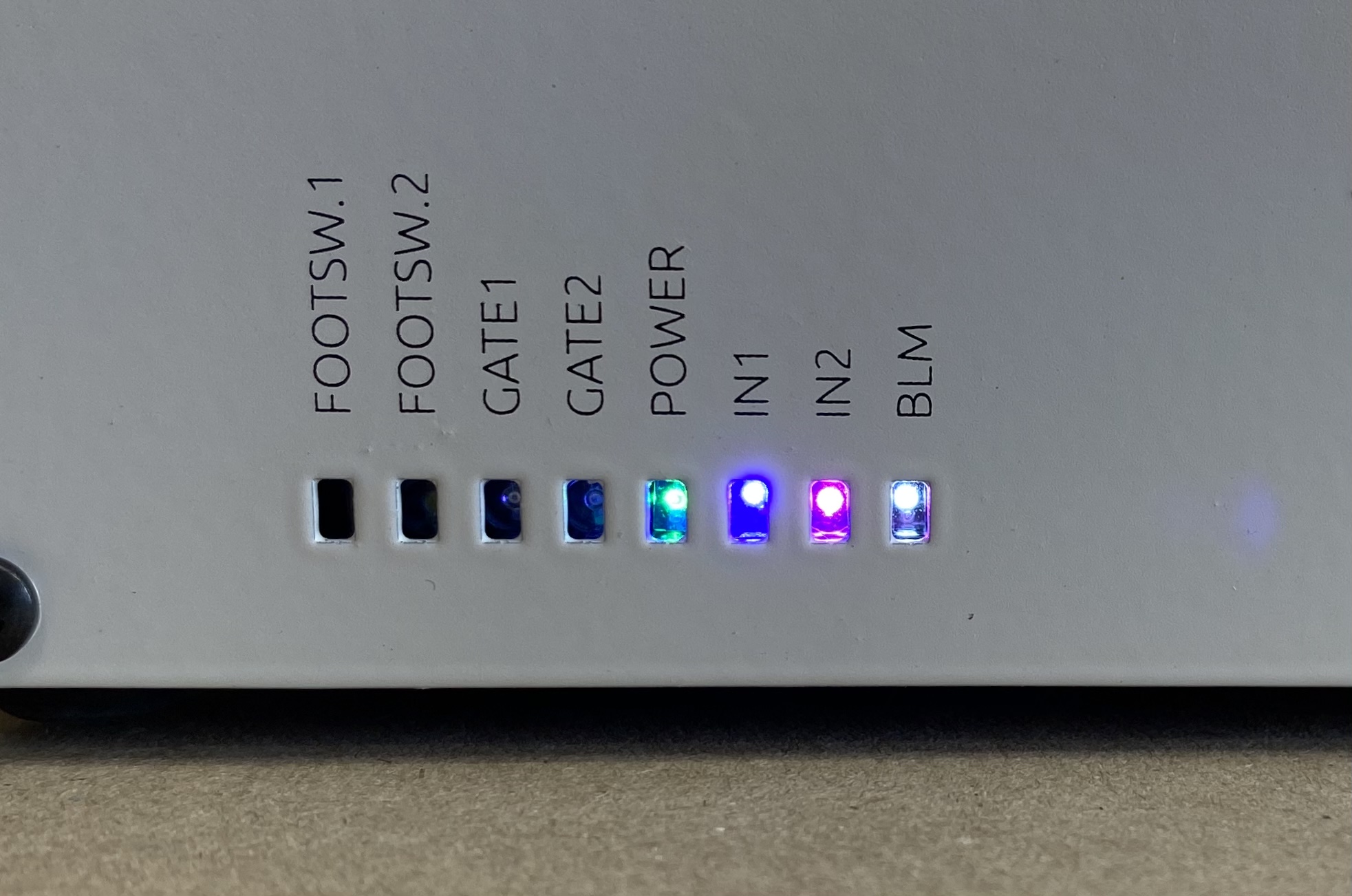
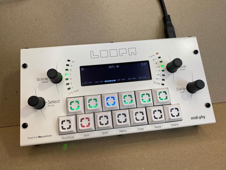
And I’m done! Seriously this was so easy (once I figured out that I needed to reflash the bootloader) thanks to Midiphy sourcing of quality components and a straightforward instruction video. It was fun picking out different color LEDs for the status indicator. Not shown are the first 4 (F1, F2, G1, G2) which are cool white, warm white, red, orange — then green, blue, pink, cool white in the pic. Now let’s see what this thing can do :) (note in the pic the screen looks weird due to the refresh rate of the OLED vs my iPhone camera)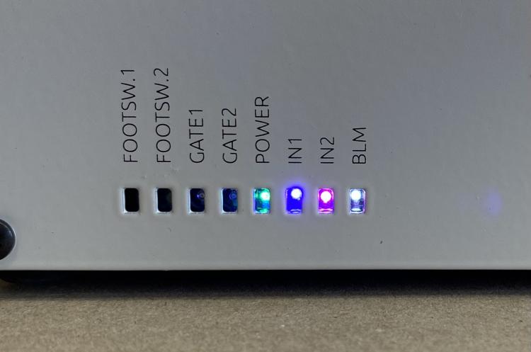
-
LoopA V2 Introduction, Features & Support Thread
armandhammer replied to Hawkeye's topic in MIDIbox User Projects
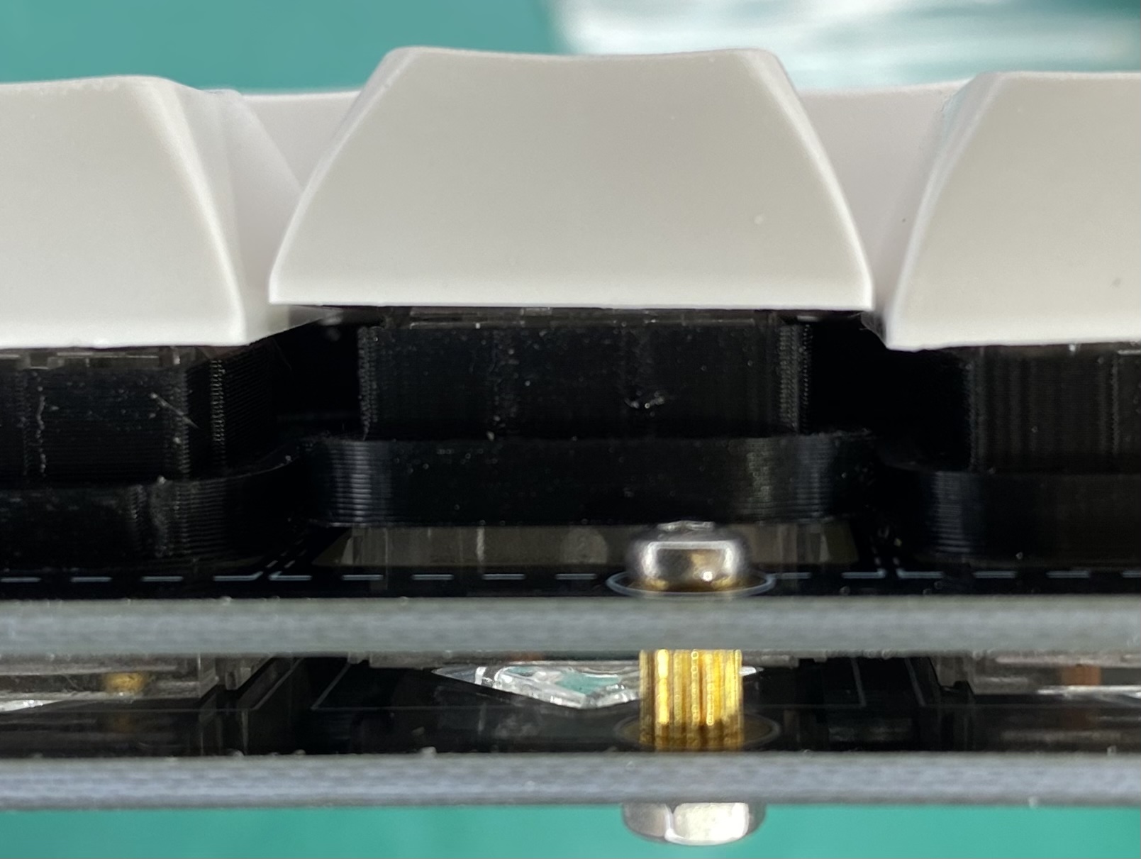
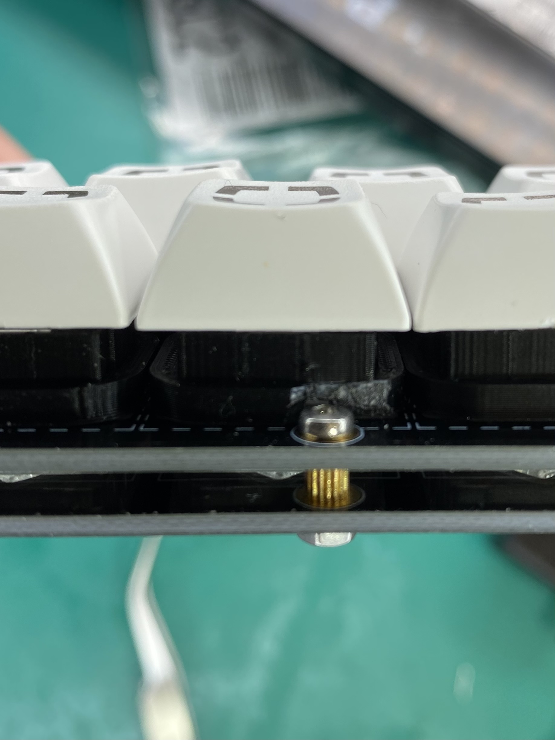
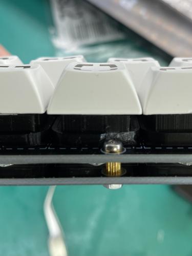
Here’s one small thing that I noticed that I didn’t see mentioned. I hesitate to post it because it’s so trivial, but the 3D light shield on the lower middle key bumps up against the screw holding the top 2 PCBs. Since the 3D plastic is so soft, it was easy to nip off a bit to make it fit flush.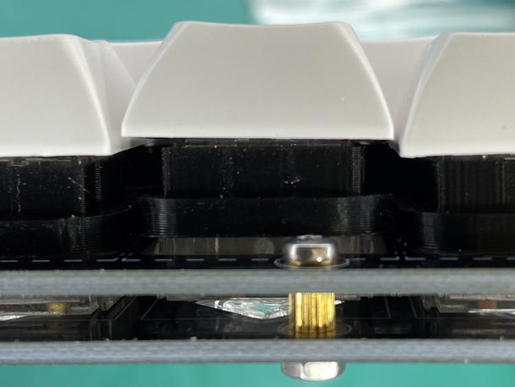
-
LoopA V2 Introduction, Features & Support Thread
armandhammer replied to Hawkeye's topic in MIDIbox User Projects
Thanks for the great tech support! I didn't do R101 and R102 because they weren't installed in the assembly video, so I thought they weren't needed (seemed ok since so many other items on the board are also DNP) but now I do see that they are on the BOM spreadsheet. My bad! One thing that would be helpful is to have more prominent links to this forum and wiki from the Midiphy product pages. I only found it by googling to see if anyone else had similar problems. I didn't even know that there was a community here... great! Anyway, I'm super excited to finish this in the morning and jam all day!!! Other than this one strange bootloader mystery, it has been a super simple build and everything is amazing high quality parts. Thank you for it, I really appreciate that this is available as a DIY kit to people like me who have more time than money :D You guys have really created something special. -
LoopA V2 Introduction, Features & Support Thread
armandhammer replied to Hawkeye's topic in MIDIbox User Projects
So what happened, then? The bootloader somehow got borked? I plugged in the full stack of PCBs and the display shows LoopA Testmode, the LEDs next to the display are flashing in a "chasing" pattern, and the status LEDs for Power, IN1, IN2, BLM are lit but the Footswitch and Gate LEDs are NOT lit. When I turn or push the encoders, it seems I get appropriate test responses on the display and the ring of LEDs. All the keycap LEDs light up. Good? -
LoopA V2 Introduction, Features & Support Thread
armandhammer replied to Hawkeye's topic in MIDIbox User Projects
SUCCESS!!!!!!!!!!!!!!!!!!!!!!!!!!!!!!!!!!!!!!! Everything seems to be working. -
LoopA V2 Introduction, Features & Support Thread
armandhammer replied to Hawkeye's topic in MIDIbox User Projects
No, it was a loose connection on a wire between CN2 and JTAG... doh! -
LoopA V2 Introduction, Features & Support Thread
armandhammer replied to Hawkeye's topic in MIDIbox User Projects
Ok I got JTAG working.... in progress... -
LoopA V2 Introduction, Features & Support Thread
armandhammer replied to Hawkeye's topic in MIDIbox User Projects
I'm having trouble getting Loopa to connect via USB to load the firmware. I get a red SMD PWR LED on the Waveshare board and that's it. My computer does not recognize that a device is connected, and I don't get the Green LED on the Loopa PCB. I've tested all of the Waveshare header pins for any adjacent continuity, there is nothing touching (only the adjacent 3.3V pins near PA12 show continuity). I checked all of the 3.3V and the 5V pins and they all show the correct voltages. I've tested continuity between the CPU and the header pins, everything is connected to the CPU. I've tested continuity from PA11 and PA12 to R30 and R31 (near USB port), it's fine. I tried connecting my PC directly to the Waveshare board via the mini USB, it's the same result, unrecognized by the PC (but with the direct mini connection, I do also see the VBUS LED). I've tried multiple different USB cables, Mac and Windows PC. Update: I read this entire thread, including Altitude's issues and the suggested checks / solutions. Nothing has helped so far. But I did see at one point Peter said "Two red small power LEDs should be lit on the Waveshare board when all is well." -- I am only seeing PWR LED, and not VBUS LED. Update 2: Removed TVS diode, no change. I've watched Peter's video a half dozen times and I can't see anything different between his board and mine. I got all my parts from Mouser, and I've done lots of SMD before so I think my work is really tidy. Just to be sure I fluxed and reflowed every connection on the board. It's still the same. Pics here. Right click on the pic and select "View in new tab" to see the full size 4032x3024 https://imgur.com/a/e5ABpzb Thanks for any help! I've been troubleshooting this for 3+ hours and can't find anything amiss. I'm happy to try JTAG stuff if someone can guide me through it. I have a STM32f0Discovery board and USBasp programmer and I generally know how to hookup the pins and such, but a bit unsure what software to use to erase and reflash this thing.