Duggle
-
Posts
992 -
Joined
-
Last visited
-
Days Won
5
Content Type
Profiles
Forums
Blogs
Gallery
Everything posted by Duggle
-
So I just reflashed Bootloader V1.012 after the flash procedure MIOS Studio displayed LCD #3 to 24 as not responding. I repowered the midibox and the bootloader displayed its test text on all LCDs correctly. I then flashed NG v1.025 and the midibox is working all correctly again. So it seems later changes are impacting the RGB LED matrix as well. Let me know what specific information I can provide to help work through this. Many thanks.
-
I've made each of the 3 changes you suggested to app_lcd.c separately and together with no difference. V1.035 (from uCapps) also does not display the RGB matrix with correct colours in half of the array. V1.036 (which I compiled) also nearly all RGB LEDs are off or incorrectly illuminated. V1.025 (which I have used a lot lately) displays all 64 RGB LEDs correctly. Would you like a complete wiring (specification or diagram)? It will take some effort here, but would be good to have anyway. I didn't do a diagram at the time I built it 3.5years ago (it all seemed so "obvious" at the the time :-).
-
Just flashed the latest from uCApps V1.035. It fixed the error with the variables (which is awsome) but it has brought back this issue for me (non-awesome):http://midibox.org/forums/topic/20232-bootloader-changelog I gather flashing the the newer firmware has replaced the bootloader with a newer one. (The change causes display CLCD #3 to #24 not responding). If I reflash the earlier one which worked V1.025 the display problem is still there. I really need to make my midibox HW compatible with the latest booloader. TK, you kindly did the file diff for me, but there is lot of code to parse to understand what needs to be changed in hardware: Do you happen to remember or have hints for what changed with the way multiple CLCDs need to be wired?
-
Hi TK, I should have mentioned the midibox is a LPC17 core. (I do use F1 and am playing with F4) The binary for LPC17 core not in the zip? Many thanks.
-
I'm using NG V1.025 which adds support for set-able variables. The idea is 3 encoders which set the midibox's Channel, instrument Part, and Port. The default.ngr contains the following: if ^section == 16 set ^chn ENC:67 set ^ins ENC:68 set ^dev ENC:69 exit endif When uploaded to the core I get the following: [30825.918] [MBNG_FILE_R:95] ERROR: invalid id 'set ^chn'! [30825.919] [MBNG_FILE_R:97] ERROR: invalid id 'set ^ins'! [30825.920] [MBNG_FILE_R:99] ERROR: invalid id 'set ^dev'! I'm not sure what's wrong. Thanks for any help.
-
I've upgraded to Windows 10 x64. The midibox ploytec driver fails with an error after connecting the GM5 during driver installation. The midijunction II 1.3.3 driver fails to see the GM5 during installation. (I can't seem to find were I downloaded the driver from....?) In both cases I explicitly deleted the default device driver before attempting installation. If I simply connect the GM5 it shows in MIOS Studio as: "Ploytec GM5 www.midibox.org" as the first port, "MIDIIN2 (Ploytec GM5 www.midibo" as the second "MIDIIN3 (Ploytec GM5 www.midibo" as the third, etc, up to MIDIIN5 now if I plug in my midibox NG as well (usb name: Beast NGb), suddenly (WTF???) MIOS Studio sees the GM5 as "Beast NGb" (port1), "MIDIIN2 (Beast NGb)" (port2), etc,etc. as well as this there is a sixth device listed as "Beast NGb" which I thought might be the actual midibox NG but no, the GM5 port 1 responds to this selection in MIOS Studio. It is as though the system can't tell the difference between the midibox NG and the GM5 interface. TK (or anyone!) if you're reading this, is there anything in the programming of my NG core (lpc17) that would make it possible for the system to seriously confuse the 2 different devices???
-
Thanks for the update. Single_usb 0 allows multiple USB ports per core which can be useful but didn't work in Windows. Could be OK in win 10 . I may try Windows 10 and midijunctioniii driver with my gm5, and ploytec gm5 driver with my lpc17 based midibox ng (ie, a multi client driver)
-
Great, that's what I was hoping to hear! Do you have any cores set up with set single_usb 0 The overly permissive privacy settings of win10 can be opted out of if one takes the time to do this (I will). The clone style backup is a good idea ( I use Windows backup image on C:/) I understand there is a rollback option as part of the upgrade process as well.
-
I'm contemplating upgrading to Windows 10. At the moment I cannot use my NG core and my Gm5 at the same time, the enumeration and device names are wrong if I boot with both connected, and neither will function! I can live without multiple midi endpoints with my NG project but to not be able to use GM5 at the same time will not do. So I'm considering the radical step of win10. I suppose I can roll it back to win7 if something else is broken. Thanks for the replies so far. I'm still very interested in this topic of how to get midi USB drivers working right with midibox cores and Gm5 etc, under win7 and win10. Comments appreciated!
-
Beware cheap (build) STM32F4 Dicovery boards!
Duggle replied to Duggle's topic in Testing/Troubleshooting
I don't think its counterfeit when all the design files including Gerber plots are published. I'm not interested in philosophical discussions. I do think newbs (and everyone, really) should not be burned by something like this. (The other stuff I bought at the same time was excellent value, though). I have no desire to communicate with these people (maybe I'll change my mind...). I would suggest for the sake of not much $$$ when it comes to the Core (so much can go wrong in the best of circumstances in setting up etc,etc) at least get the Core from a reputable source! -
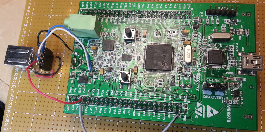
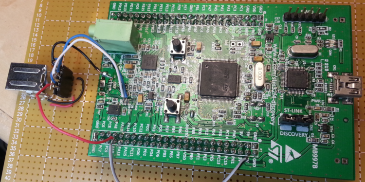
I received my first F4 Discovery board from an Chinese ebay seller along with some excellent value LEDs and an LCD display this week. The F4 was able to be flashed with it's booloader through the ST link as per TK's instructions. It was when I attached the target USB connection that didn't work, that I spent quite a few hours to sort things out. I found: various short circuits under CN5 (the target USB port) USB data line short circuited by a solder bridge. SMD capacitor open circuit (not properly seated) Worst of all(!): CN5 was the wrong kind of connector for this PCB. It was a micro USB receptacle, sure, but one designed for a PCB such that in this case the logo on the cable plug faces down. The result is that all the terminations are made in reversed order(!!!) It took me by surprise after many confused hours. For example why was the Vbus sitting at -0.7V rather than +5V? (Because with power attached backwards the 5V rail was being clamped by the diode action of a nearby logic chip, which was getting warm, btw) Happily, and perhaps miraculously the board is now working (at least the functions that I will be using). I removed the CN5 connector with a hot air gun (after carefully wrapping the PCB in foil to protect the rest of the board from the heat). I soldered 4 wires onto the PCB for the USB connector mounted on the baseboard.
.thumb.png.f0e98c2b6fca00e6f2199b857bfa2979.png)
-
Is that the one that says it's for Midijunction iii (or something)? Have you had issues with core32's enumerating as GM5?
-
Thanks for chiming in. Windows 7x64 has been really good to me overall, but I think weaknesses in USB midi are well known. First of all, I could use the installed GM5 driver with the bootloader jumper J27 closed. If I then flashed NG, I could use it for the remainder of the session until re-boot or reconnect. It wouldn't work and the computer would hang during "shutting down..." at restart/shutdown. I ran the GM5 un-installer a few times but the NG would come up with the GM5 driver in device manager. To eradicate it I followed this: http://www.thewindowsclub.com/how-to-remove-old-unused-device-drivers-in-windows-7 basically with NG not connected, reboot, make unused devices visible in device manager then from there uninstall and check "delete driver files". Now the NG comes up as a device with the name I gave it in the bootloader rather than "Midibox.org GM5". It seems to work well! Does anyone know what Windows 10 is like for USB midi?
-
I've used my GM5 midi interface with the Ploytec drivers for many years without issue (Win7x64 PC). I've recently resurrected an old Midibox NG (LPC17) project and am having much difficulty getting it to work reliably or at all with it's usb midi (on same machine). I've ensured that the bootstrap setting of set single_usb 1 to eliminate the possibility of the windows/usb multiple connections issue. I find that the NG is bound to the GM5 driver. I found that this midibox NG project connected properly to a laptop (win7x64) that had never seen the GM5 drivers. Is there a way to force this midibox NG to bind to the legacy (non GM5) drivers? Are the newer Ploytec drivers appropriate for this situation? Thanks for any suggestions or comments.
-
I've used the method you've provided and it works ok, as a simple interval timer, auto repeating by default. Once the interval becomes too short <=4us, the system gets stuck and hangs. This means I need another approach. I'm now in the process of researching how to program the timer registers directly (with the perpheral library) which is time consuming, but will yield very high resolution low cpu performance for the complex patterns required.
-
Tiny feature request for MIOS Studio
Duggle replied to Duggle's topic in MIDIbox Tools & MIOS Studio
The 2 instances that concerned me were as I mentioned Midi rescan, and what happens when I start MS with the command line (to launch GUI) that contains a batch command in which case there is a "batch job completed, ok", or similar pop up. If it was easy enough to suppress the pop up and instead direct a text line to the console (that is in some way distinguishable from normal console ouput) then fantastic, if not, no problem. -
Tiny feature request for MIOS Studio
Duggle replied to Duggle's topic in MIDIbox Tools & MIOS Studio
That will be really nice! The feature that requires too much work, I agree, not worth it. The idea for a switch to suppress all pop ups I didn't give much thought to, in fact the only other pop up I was thinking about was the batch jobs complete which I was only noticing on startup. This (but I'll look into it further). Thanks for considering these requests! -
Hi TK, I'm using STM32F1x. The application is a complex square wave generator with the interval changes in a state machine inside the ISR. I'll try your suggestion.... Thanks!
-
I'm initialising a timer from App_Init() MIOS32_TIMER_Init(1, 20000, TTest, MIOS32_IRQ_PRIO_LOW); The routine is void TTest(){ static u32 PulseCount; //counter variable MIOS32_TIMER_ReInit(1,50000); if (++PulseCount&1) delH(100); else delL(200); } The port pins are sent high and low with a short soft delay with delH() and delL(). The pin toggles very fast (nothing like 50ms). The ISR is being triggered repeatedly so fast the application hangs. Is there anything obvious in my usage?
-
I guess the most obvious problem would be when special function pins used by MIOS32 are assigned to other functions on your board. Potentially a lot of time and effort to resolve. Or maybe not, it depends on the board. As was alluded to, the cost benefit balance probably isn't there.
-
Tiny feature request for MIOS Studio
Duggle replied to Duggle's topic in MIDIbox Tools & MIOS Studio
I guess the background of this request is the process of coding and testing, which can involve a lot of repetition so you really notice things in the GUI that slow you down unnecessarily or add "work". In fact a switch to suppress all notification pop ups and instead print a message to the console window in another colour would be great. The other pop up I'm thinking about is the "Batch job complete, ok?". It's helpful to be made aware that commands have been executed automatically, but unhelpful that you have to click the button to continue- every time. Thanks. -
The command line switches feature added some time ago have been an awesome improvement to MIOS Studio. I'd like to request an additional switch: It's about the pop up message box that appears every time Application/Rescan MIDI Devices item is selected from the menu. As a windows user, developing code etc, I use this action a lot and the pop up is a PITA. I know this feature is to help newbies avoid confusion so it has to stay. I'm requesting a command line switch to turn off (suppress) this pop up. Many thanks.
-
After looking at the NG source code, the protocol is corrected in the initial post of this thread. This means there are only 12 levels of VU and this input range is scaled across the 16 levels of "pos" in the LC_METER_PATTERN statement. LC_METER_PATTERN pos= X pattern=RRRRGGGGBBBBV000 So only 12 blocking diodes required. My main host is Ableton which, according to the Midi Remote script for Mackie Control, simply outputs 0 to 12 (no clip or reset of clip state that I can see...). In this case I'll probably define the clip LED to come on at the same time as maximum VU (=12, that's C) but that's defined in the default.ngc which is easy to change...
-
First of all, I've had great results in the past with NG RGB support (an application of PWM, or pulse density modulation in the case of NG, I think), and that's with 64 RGB LEDs used to "colour code" control elements on a large MIDIbox. The idea I presented here only requires a total of 15x(1N4148 or similar) signal diodes. What you get is fairly precise colour and intensity for the 8 LED's with each of the 15 levels of VU which is presented as a colour gradient with respect to VU level. This is done without modifying the sw, just specifying the RGB for each VU level in the default.ngc using the existing LC_METER_PATTERN statements: LC_METER_PATTERN pos= X pattern=RRRRRGGGGGGBBBBBBV where X has values 0..15,(VU levels) and O (clip) pattern has values (0..1) for R,G,B (5bits each), and V is the position of the clip LED. There are only 8 RGB LEDs involved. I've had very good results previously with RGB (multiplexed by 8 columns) with NG in the past. (I should post a video of my last NG project with RGB LEDS) In this instance there will be 5 pins driving each R,G,B element (albeit with a higher resistances on the additional pins) It should be at least x2 brighter than the standard bar graph LEDs. Unless I'm wrong of course, but it is an easy experiment so I'll certainly let you all know how it goes.
-
Hi TK, Thanks, I just discovered the logictrl.ngc template I was using pre-dated the LC_METER_PATTERN feature! I had thought of some kind of LED meter but was attracted to the LCD because it would make use of unused CLCD display real estate and require no hardware construction. I suppose the LC_METER_PATTERN only works with simple DOUT matrix not RGB? Because I haven't much space for a bar graph, I was thinking of an RGB that would display a rainbow of colours and intensities with maybe one extra red LED for clip. Actually, as I type I'm having an idea to implement this with without sw modification: As there are (up to) 16 rows that determine the output pattern for 16 VU meter levels, the idea is to "decode" the 16 rows into 3 rows RGB with a diode and resistor of each input row. Here's a schematic: Of course I would use the LCD meter option should it become available anyway because even with the LEDs, the character display is not completely spatially aligned with the BCF2000 channel strips.
.png.ce10e7c2c9d3e5b7b02a64bc05fc1fea.png)