

Duggle
-
Posts
992 -
Joined
-
Last visited
-
Days Won
5
Content Type
Profiles
Forums
Blogs
Gallery
Everything posted by Duggle
-
For now, forget about the ULN (unplug it if you can). We are only interested in being able to control the output of a DOUT pin so that it toggles 0..5V Is the SR we are looking at really SR1? (the first in the SRIO chain) Please disconnect any other SRIO's from the chain. I just looked at your photo. It really makes sense to use IDC connectors and ribbon cables when working with DIN and DOUT PCB's!!!! You can split the ribbon and route the wires as needed, then you can disconnect the DOUT PCB easily!!!! Another question: is the ribbon to J1 correctly connected to the core? If you can't get basic LED on/off like in the "Getting Started" tutorials, then the fancy RGB matrix won't work either. This is why it would be good to follow the basic tutorial, make sure everything is set up and working right, then getting the RGB stuff to work will be straight forward.
-
Lets just get the basics right, first, then take it from there. If you could restore the definition for row#1. As I understand it, without button_mode=Toggle, you should see 5V when key#36 is pressed and 0V when it is released. With button_mode=Toggle, press the key ->5V, press the key again ->0V, and so on. Either way we want to see 0v and 5V on the output of the DOUT under midi control.
-
Can you unplug the matrix from the DOUT and just look at the pins from the shift register. I would have thought that pressing note#36 SR1,D7 (row1 driver) should go to 5V. Measure signal before the ULN2803 (i.e on the input pin of the ULN) The idea of the Button toggle mode is so that you have (push on/push off) toggle action, makes it easier to observe.
-
Thanks for reminding me.
-
No problem, I'm happy to help, but have limited time to type long messages. So ask questions if anything is not clear, and carefully explain what you try and what you see or find out. Good to know. Now we are going to temporarily abandon matrix mode, and drive the rows and columns manually to see what's going on. Comment out or delete the whole line beginning with "DOUT_MATRIX n=1" Now we address the rows and columns as if they are single wires with single LEDs attached to each. Please refer to MIDIbox NG Manual - First Steps - Let there be light! - and- "Remote me!". This demonstrates driving an LED line with a MIDI message from MIOS Studio. Note that in this instance "fwd_id=LED:1" actually relates to the first row driver pin in your design. Understand that LED:n addresses each pin of the DOUT SR array. Set up EVENT_BUTTON definitions for each row and column, don't worry that you don't have DIN attached to your core because you will be activating these events from the virtual keyboard. #row 1 EVENT_BUTTON id=1 fwd_id=LED:1 type=NoteOn key=36 button_mode=Toggle #row 2 EVENT_BUTTON id=2 fwd_id=LED:2 type=NoteOn key=37 button_mode=Toggle #row 3 EVENT_BUTTON id=3 fwd_id=LED:3 type=NoteOn key=38 button_mode=Toggle #row 4 EVENT_BUTTON id=4 fwd_id=LED:4 type=NoteOn key=39 button_mode=Toggle #column 1 red EVENT_BUTTON id=5 fwd_id=LED:9 type=NoteOn key=40 button_mode=Toggle When you press key 36, row#1 should be active, press it again and it should go in-active. Measure the output pin of the DIN with a voltmeter to see that this is so. I'll stop at this point let me know how you get on, before we continue.
-
I'm suggesting you take a step by step approach to discovering what is going on with your LED array. I've made some very specific suggestions. It is up to you if you want to do it, or not. Now, can you confirm the the LED's are common cathode or common anode? (Do you have data?)
-
Do not change the wiring! Change the configuration in default.ngc so that you can individually control each row and column of the matrix separately, using midi key events. This is so that you can isolate the problem. Do you understand the idea?
-
Sounds like a wiring problem. To isolate, please temporarily change the config to straight LED DOUTs rather than MATRIX. My suggestion is to set up each DOUT pin as EVENT_LED in toggle mode with a unique midi key to control it. Using MIOS Studio keyboard events, individually activate each row and column to find out if you have control over R,G,B of every LED (by itself). They will be rather bright because there will be 100% duty cycle. As the lines are not scanned (they will be in a steady state), you will be able to trace the voltages with a multimeter (if you get incorrect results).
-
When I changed my array from 8x8 to 4x16, I added a DOUT PCB that already had 220R fitted (The first DOUT had 82R fitted). So half is 82R the other half is 220R and it is not at all clear that one half is brighter.... I think this is because the current limiting is mainly in the SR's. Conclusion: it probably doesn't matter. It may be a good idea to test the brightness on one or two LEDs before you solder a whole bunch of resistors anyhow... You may want the whole array dimmer for some reason. Also it may be good to check that R,G and B are fairly balanced with the same value resistor. In my case they were, but...
-
Here's an excerpt from my config: #rgbled DOUT_MATRIX n=1 rows=4 inverted=1 sr_dout_sel1=1 sr_dout_r1=2 sr_dout_r2=5 sr_dout_g1=3 sr_dout_g2=6 sr_dout_b1=4 sr_dout_b2=7 led_emu_id_offset=1001 # LEDs go to colours according to bank selection EVENT_LED value=127 id=1001 bank=1 rgb=15:0:0 EVENT_LED value=127 id=1002 bank=1 rgb=15:0:0 EVENT_LED value=127 id=1003 bank=1 rgb=15:5:0 EVENT_LED value=127 id=1001 bank=2 rgb=0:0:15 EVENT_LED value=127 id=1002 bank=2 rgb=0:0:15 EVENT_LED value=127 id=1003 bank=2 rgb=7:0:15 EVENT_LED value=127 id=1001 bank=3 rgb=7:15:0 EVENT_LED value=127 id=1002 bank=3 rgb=7:15:0 EVENT_LED value=127 id=1003 bank=3 rgb=15:7:0 The way you have your config is to light the LED's only when the note is active.
-
You're using common cathode RGB LED's right? If so, you cant use ULN2803 as drivers on SR2..4 because ULN2803 is a "low side driver" (Darlington NPN) and won't work as a high side driver. If your LEDs are common cathode, move one of the ULN's onto SR1, remove the others and replace with a resistor (SR2..4). Also change to "inverted=1". This configuration works geat.
-
Well spotted! It seems TK has been quite busy with this in the first half of june, according to the repo logs. He's posted benchmarks that show at least a pro-rata increase in performance (for all except USB midi, interestingly). The tests are at 168MHz. I guess we'll hear more about all this in due course.
-
I'm well acquainted with the single USB port option. It can make a huge difference, but it does not entirely 100% fix the occasional failure to communicate.
-
I get some similar issues, sometimes. I usually power cycle the core and restart MS when this happens.
-
if I connect SD Card - LF33 will be very hot in a short time
Duggle replied to Rio's topic in MIDIbox SEQ
Not normal. You need to: Check the wiring terminations between card and core (are all the connections correct?). Check the card in another computer (Does the card work?). -
It seems like the main difference is life (and price, I presume). 1 million rotations is a lot of midiboxing. But then so is 100k! Also, I think the actual difference between 32 and 24 pulses per rotation is probably not that big either.
-
Thanks, tested o.k.! :smile:
-
I've just got an Android tablet working with my DAW (Reaper) which has support for TouchOSC in the form of a layout called LogicPad. So I purchased TouchOSC for about $5 (what value!!!) and set it up with the LogicPad template. In Reaper I set up a control surface config for OSC selecting LogicPad support. Set appropriate IP and port numbers at each end. The result: fantastic! :frantics: A number of pages including full control over mixer, with full feedback and track name (labels exactly as they appear in the DAW). Other pages have full control over plugin parameters.etc,etc. This would appear as the closest to a really "out of the box" workable way for control surfaces to work, especially with DAW where there is so much flexibility, that static mappings don't cut it. Though great, I think in the long run tablets aren't the ideal control surface vehicle because of lack of tactile feel. You really have to be looking at the controls as you use them. So what I'm now very interested in is working with OSC with MIDIbox NG! I notice there is transfer_mode property of an OSC definition that is for TouchOSC. This seems to be a good place to start because I've seen how it can work with a DAW, and have one that does! I'm new to OSC and pretty clueless. Are there any use examples of OSC for MIDIbox NG (especially as I've outlined)? I've seen an OSC monitor by googling such as:http://www.kasperkamperman.com/blog/osc-datamonitor/ Is there a way of "inserting" a monitor to observe a 2-way interaction? (I'll have to experiment)
-
You didn't mention what trial and error you actually did... Anyhow, I'd be trying things with this property button_mode=<mode>
-
From the album: Duggle
-
From the album: Duggle
-
From the album: Duggle
-
From the album: Duggle
-
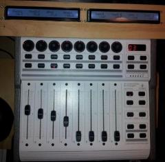
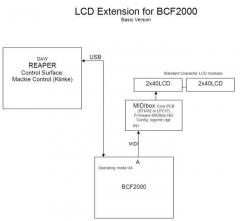
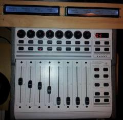
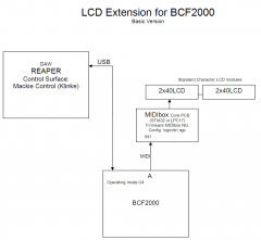
I'm using the logictrl.NGC file from the repo to create an LCD display for my BCF2000 control surface. The Core STM32 is connected to the MIDI In and out of the BCF2000 which is USB'd to the DAW (Reaper running Kinke's MCU extension plugin). So the Mackie control option is what I'm using. I commented out the RECEIVER/SENDER pairs which implement the responsive aspects of the protocol (this is being done by the BCF2000) I'm really only using the Sysex receiver for the display of LCD text in NG so far. Works great! I'm now thinking about adding buttons and extra functionality that the BCF2000 lacks. Now to my question: the logicntrl.ngc does not implement VU meters. I recall the old PIC project has them. Is it possible to add them? What midi messages would correspond to the VU levels?
-
I'd assume the expression pedal is a potentiometer. The wiper will change it's resistance to ground. Tip or ring? Find out with meter. The 3rd terminal will have constant resistance to ground. This is wired to 3.3V supply rail. The wiper goes to the ADC input of Core. Configure using EVENT_AIN.