

forestcaver
-
Posts
17 -
Joined
-
Last visited
Content Type
Profiles
Forums
Blogs
Gallery
Everything posted by forestcaver
-
[FS] Core8, SID, DIN, DOUT, Ultracore, I2C DIY stuff
forestcaver replied to rosch's topic in Fleamarket
If you still have the i2c quad midi board I’d be interested please. -
I am trying these as they are similar but a little smaller - will update if they work… https://uk.rs-online.com/web/p/memory-card-connectors/7636794 EDIT: It works fine - but footprint is a bit smaller so may need gluing as well if the card is going to be removed often.
-
Does anyone have spare sd card holders for the core or a suggester part substitution? (It is actually for a different pcb but is the same part as used on the stm32f4 core) 3M have stopped manufacturing them and I havent found an alternative that is the same size as SD-RSMT-2-MQ or SD-RSMT-2-MQ-WF ( I have found 9/11 pin versions which are shorter with different positions for the mounting tabs). Thanks a lot.
-
Seq v4+: Left LeMec board troubles
forestcaver replied to geekraver's topic in Testing/Troubleshooting
Excellent ! Great news ! :-) -
Seq v4+: Left LeMec board troubles
forestcaver replied to geekraver's topic in Testing/Troubleshooting
Ah, ok - apologies - was just trying to help with some suggestions and was commenting on the shared photo. As I’m sure you know, you can often reroute lifted pads by using kynar wire or similar.... Reason I asked where you lived was that I was going to offer to look at it for you if you lived near me and wanted to drive over (shouldnt need to be said, but for clarity, not for any remuneration - just to be friendly. I have no interest in taking money for any DIY stuff - it’s just a hobby). I was making a (very) wild guess that is completely wrong that you were in the UK - again, apologies for any assumptions.... good luck. -
Seq v4+: Left LeMec board troubles
forestcaver replied to geekraver's topic in Testing/Troubleshooting
Hi - 1. Midiphy people will send you snippets of the schematic if you ask (sub-optimal, I know, but better than nothing. When I built mine, the lack of schematics was a major concern for me too. Looking at the midibox schematics can help understand the midiphy reworking - look at the DIN shift registers and anything in that chain first for the inputs - it should be pretty solvable). (For background - I’ve built a midiphy seqv4+ and two seqv4s, one of which is very fully loaded) 2. There are issues with your soldering (sorry !) but even in that one photo there are loads of suspect solder joints. Type of solder, heat, flux, technique, etc can all contribute ! (Sorry to be negative!) 3. Do you have any magnification ? (Seeing what you are doing makes a massive difference - I use a stereoscopic microscope with a decent working distance - it’s pretty essential for me to build things reliably) 4. Where do you live ? (Your online accent implies UK !) -
I prefer the first tbh... :-)
-
The flex is acceptable (to me) compared to the price of frontpanel express !!! (The Wilba board is fine but the BLM and IO panels have a little flex due to less material - I am toying with the idea of epoxying an angle strip to the back for rigidity but havent needed to.... I have a breakout pcb that takes the outputs of the dout and aout_ng and feeds the jacks. (I used an extra spare pcb that I drilled to mount the standoffs for the dout and aout_ng). It connects to the 4x 10-pin headers on the dout and the 16-pin header on the aout_ng via ribbon cables. The board I am using is a little too tall for 2u but I have made an (untested) board that is a better size for the 2u panel. Next time I order pcbs I’ll order the revised one.... I can share both with you if you like - maybe by PM, as the revised board has not been tested yet and I am not 100% happy with the one I am using due to size ??? If you’re in the UK, you can have a couple of them if you like ! I am off on a remote caving expedition for the next 3-4 weeks in a few hours (!) So it wont be until I get back - PM me if you want the boards... (and send me a reminder in a few weeks as well !)
-
Also - the frontpanel express files for the IO panel (I think the other two are available in the wiki - if you cant find them, let me know but I’m pretty sure I used existing files - may have made minor edits - but not to holes etc - so probably not right to share them !) AJH_IO_06.fpd
-
Thanks - panel files are attached - these are Eagle PCB files - I ordered from jlcpcb and I ordered aluminium pcbs - they were between $4 and $6 for each pcb/panel (there are three panels) when you order 5 of each - so about $20-$30 for 5 sets of 3 panels. I ordered black silkscreen and white soldermask - the files below are set up for this, as it arrives at a higher resolution and with less bleed than doing it the obvious way around. These are 1.6mm thick - I doubled them up - so used two pcbs for each panel to have a thickness of ~3mm to increase stiffness and thickness, at a cost of ~$10 total for each panel - so about $30 for all the panels you can see above. Hope that is helpful.... AJH_IO_10.brd AJH_TPDBLM_19_v02_07_bSSwSM.brd AJH_wilba_mbseq_19in_opt_04_bSSwSM.brd
-
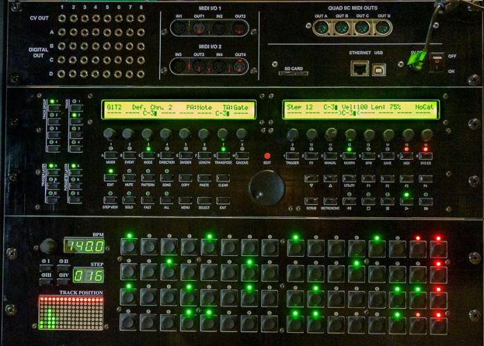
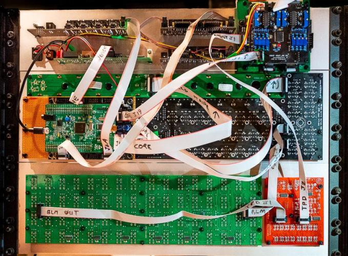
Finished my Seq V4 - Wilba CS, stm32f4 core, 2x midio out, 1x iic quad midi, 16x4 BLM, TPC, AOUT_NG, DOUT, cutom breakout board for DOUT and AOUT_NG and the Westlicht seqboard (for SD card, etthernet, +/-12V). Only issue I have is that there is up to 25mV offset on a couple of channels of the AOUT_NG, which is within spec according to the tlv5630 datasheet - I am going to make another AOUT_NG board with dual inverting output stages and a trimmable offset I think. Otherwise I am really happy with it - thanks to all the contributors !
-
If anyone has a spare pcb I’d be very interested please. Thanks a lot…
-
PM sent
-
Looking for frontpanel for SEQ in Heidenreich case
forestcaver replied to verpeiler's topic in MIDIbox SEQ
Just a thought - I used jlcpcb to make front panels from 2mm aluminium pcb - about $29 for 5 panels (I used two 1.6mm thick parts for a front panel in order to make it more rigid so $12 for a panel). I’m really happy with it given the cost.... (mine were for 19 inch rack) -
Thanks - looking forward to seeing it !
-
Nice (I’ve used them for a couple of projects in the neotrellis) - it’ll be really nice and compact - I’d be really keen to build one when you finish it :-)
-
Nice! What are you planning on using for buttons/pads?

