
Jidis
-
Posts
838 -
Joined
-
Last visited
Content Type
Profiles
Forums
Blogs
Gallery
Posts posted by Jidis
-
-
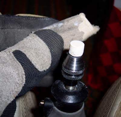
I've got about three different heights of parts on this thing I'm working on. Most of the switches have homemade caps, so I can make them tall, and the pots have long enough shafts, though I'd rather that metal part at the base have made it through the panel for strength.
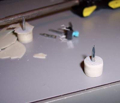
These switches on the other hand are going to sit about 8mm below where they need to be:
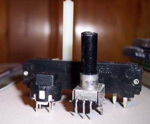
Have any of you guys ever run into that? If so, what did you do? I was thinking of pulling some of the pins from one of those machined pin sockets (with the round holes), and soldering the buttons legs into them (like stilts), but the pins on the button are sort of fat. Other option I guess is gluing something to the tops and losing the look of the nice square plastic cap. :'(
??? ??? ??? ???
George
-
Ladies and Gentlemen....... This just in:
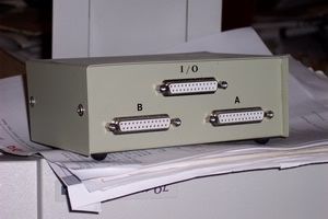
Couldn't help it Mark. It was on a shelf right in front of me. ;D
I just throw the photos on this thing called Photobucket (http://www.photobucket.com/). They show up in an "album" and you can copy/paste a link to them in places like this. I don't know if it's a good or bad site, it was just the first one I found when looking for a free place to host jpgs. Seems to work OK with little mess or ads. If it dies I guess I'm doomed though. 8)
Take Care,
George
-
Henry,
Not sure if it's the exact same scenario, but for pulling down random analog pins, I've been putting 8-way DIP switches on my Core. I actually started off using a dual row jumper block with a row hitting the analog lines, and the corresponding row all ground pins. That was a dual purpose header, where I could pull any or all 8 lines off to pot(s) and keep the jumpers on the rest, but that requires weird cabling to go out from the header to the pots. Now I just link all the pins on my analog header block to a similar setup with one of those multi-switch DIP switch things, with one whole side tied to ground. The wiring was pretty easy, as I just soldered a strand of wire across the base of the switch on one whole side for ground before installing it, so it really only needs the one pin at the end tied to ground. The other side can just sit inline somewhere with the analog pin paths (hope that makes sense).
I guess you could do the same with the lines headed to a mux chip.
Here's the older one with the jumpers:
And the new DIP one:
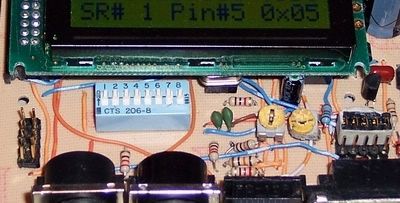 - The "shorting" wire is actually under the switch, on the top of the board.
(the analog inputs are that 2x5 header over on the left)
Take Care,
George
PS- Right now, I'm trying to do a Core on a piggyback daughtercard, which will mount to the main (pot/light/switch) board using a 2x8 header block on one and a female socket on the other, along with a standoff or two on the other end. If it works I may start making multi-layer projects with small boards, that "squash" together like that. Imagine a five-deep stack of MBHP boards, with standoffs, locked together like a small rectangular "brick" ::) ::).
-
Hey again,
Around the middle of this page:
http://www.opamp-electronics.com/tutorials/special_purpose_diodes_3_03_10.htm
there's a 6V LED circuit with a 220ohm, and he calculates it to 88mW and says the 1/8W is enough, so I guess I'll go with those.
Take Care,
George (building a giant Digikey order and a drill press and a MIDIBox simultaneously ...perhaps)
-
Thanks!
So I'm fine on 10k pullups then.
What does the average 3 or 5mm "standard power" LED pull?
(sounding lazy as s*** right now)
George
I'll look around a bit anyway. :)
-
Is that all they look at (the area/zoning)?
I had an LED maker turn me down once, and I listed my studio's name, but with my home address. They said they couldn't find a "business" under that name. ???
George
-
I only see one mention of them in the Deutsch forum. Around how much are the average i/o pins looking for with stuff like this (pullups on the DINs and LED current limiters)?
Just being safe. ;)
George
-
Michael,
Thanks again. This will likely be in assembler though. :'(
The mod key/odd pin doesn't scare me so much as the app itself. I'm going to try to do it from the skeleton up, and I'll probably be "dead in the water" after the first couple lines. ;D I figure maybe if I just go ahead and make the thing, it will be some incentive to fight my way through the app, but I'm trying not to set myself up for too much disappointment.
George
-
Much thanks both of you!
Looks like I'm OK with any of the mux lines since I'm just running the eight pots. :)
I was mainly just wondering if any of the pins were any more difficult to access for something weird from within the app, as MIOS has so much happening on the OS level. I was afraid of crashing into something happening behind the scenes. :-X
George
PS- Sad, but I've had that pin list, but haven't looked at it in a while, and just saved another copy to take with me the other night. I got mixed up and somehow remembered it as the same info that's in that port listing on the Core's page. :-[
-
No, I think that was a gift from the City (those kind souls). ;D
-
Hi,
I'm throwing together a layout and have a switch in it which I was planning to try to use as a modifier toggle later on (it isn't a momentary). My DIN/DOUT circuits right now come to nice even multiples of eight and I've got that one stupid switch left over.
Assuming it's OK to do, what's the obvious PIC pin to grab for that?
Right now, I'm running 48 lights (6-595s), 16 buttons (2-165s), 4 faders & 4 pots (directly to PIC). My connections for all that will be the regular Core stuff (bank A for the pots/faders, RD0-3 for the DIN/DOUTS). There will likely be no other i/o components (except MIDI of course).
Thanks,
George
-
Henry,
Forgot to mention:
Not sure what you're doing with the patches, but if you're looking into making parts or enclosures, you might want to check into the "Bondo" type fillers and two part fiberglass resin. I did an enclosure a while back with that ( http://www.midibox.org/forum/index.php?topic=4411.0 ) and use it for parts as well. You don't really need the Bondo (putty) part for most stuff I guess, but it can add strength for certain applications and with the right mix, can be spread about like peanut butter or poured into a mold if more resin is added. It also mixes with certain paints.
Take Care
-
When you said feet, I thought you were going to describe something like this:
--- That's a fake BTW. I sanded it for real with both hands but couldn't hold a camera like that. ;D
George (longing for that prehensile tail :'()
-
Thanks for the links!
Did that guy do a "random" Sodium Persulfate mix? Heck, mine doesn't even work when I try to measure it. Maybe I should try his approach. ;D
--- Come to think of it, it's too "green". Looks more like the acid I'm running now. ???
-
Nym,
Check these guys- http://www.mcmaster.com/
Thank RTurner for that one. ;)
George
PS- One of the few good DIY things I've found in this town is a sheet rubber supplier called Sutton Clark (http://www.suttonclark.com). I've bought sheets for drum pads before, but for full-size pads (not finger buttons).
-
BTW- Those router bits cleaned up OK. I discovered them the next day and hit them with rust remover then wiped them down with oil. They were mostly cheap highspeed steel junk anyway (relatively disposable). Also, I wore a filter mask (the kind with the filters in canisters) this last time on the acid, even outside. I guess that's overkill, but it was nice to not have to worry about any airborne "clouds".
Went inside for another Sodium Persulfate attempt a few days back, as it was cold and late, and sat through almost two Sanford and Sons stirring the crap and waiting. For the last 20 minutes or so, I broke down and went up and grabbed an old coffee pot and moved it to that for some heat. I started off with it in a plastic bin, surrounded by hot water, which never transferred all that well to the etchant. Still don't know what I'm doing wrong with that stuff. ???
-
My deal would be after everything had been powered up and thoroughly checked. A lot of these things aren't destined for enclosures, so any reinforcement helps.
George
PS@ Robin- I didn't even realize you were that close. I'm right up in Richmond. Still looking for the "good" electronics store here too. Just had to resort to RS the other day for some small junk. Resistors are a dollar for five on 1/4 watts. :-\
-
I hate jumperwires, and I rather connect 2 boards with wires than jumpwire the one board.
I'm the same way, but I've finally decided that if I'm never going to make anything more than once, I may as well just get as close as I can with the layout, then run a bunch of wires for the leftover.
Funny you mention the two board thing. I was thinking a while back, of trying to do some modules where the Core,etc. plugged directly into the i/o boards in a "piggyback" style, maybe with standoffs and nuts/bolts holding them at the corners. This last board got me thinking of a similar idea, but rather than headers & sockets, if you had two boards of identical size, did as much of the traces as you could on each one, then cut a handful of jumper wire (maybe 3 or 4 inches each) and just wired them directly to pad holes, so you had two boards chained together, then rotated one a couple times to twist all the wires together, "squashed" the wiring in-between the two boards (like a sandwich ::)), then installed the standoffs and screws to hold it together. Might look sort of cool if it worked and might make the layout easy, as you could jump from any point on the board to any other with no visible wires, plus you'd have the extra board space of a "pair" of boards (unlike regular two layer PCB).
Take Care,
George
-
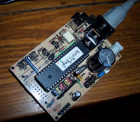
Yeah, I like the Core a lot, but it was a similar pain in the a**.
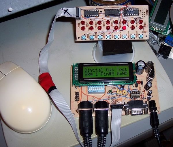
The area over on the right is a JDM. Above the 9-pin socket is a two way, 5-pin header (3x5), with a group of 5 jumpers glued together. If I pull that off and move it to the other side of the header, it's a JDM (in ICSP mode). The bottom header (with the ribbon) is a 2x5, but rather than the duplicate pairs of pins on the regular J8/J9, it's got the top row wired like the DOUT regular part, but the bottom is the DIN data line, and the three mux lines for analog in (I'll make a ribbon if I do that). The left header is the 8 analog pins, 5V, and ground on a 2x5 header, and the DIP switch under the LCD/PIC can pull down each of those depending on how many I need to use. The LCD is plugged into a sliced off chunk of an old Mac Nubus connector. ;D
I really made it for doing non-MIOS things where I can't dump into a loader, but have to keep reprogramming and rebooting the PIC. I didn't like the idea of having to keep pulling the PIC or having separate boards with an ICSP connection.
Next step is to get a board or two to adapt smaller chips to the 40-pin with their i/o pins going to the right places. :) -> The xtal is socketed BTW
George
-
Funny, I just did the same thing with the hotmelt. If you notice, the LCD on that Core has mounting holes. I had standoffs under it, and didn't have long enough bolts, so I just used screws with a glob of that on the bottom (on the tip of the screws). That barely came off and it wasn't even really stuck to anything but "flat board area". :o
I think the gluing I'm looking for on this stuff would be more permanent. The sort of thing where if I needed to change something, I'd rather build it again. I guess you're saying hotmelt is OK for that?
Take Care,
George
-
Thanks Sasa!
Yeah, it's just a switch/light board for playing with stuff. It's two 595's and a 165. I made it so it could be chained to another,etc., but it was such a pain in the ass, it isn't worth doing any more (too many vias and jumpers). :(
George
-
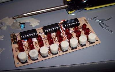
I just made some caps to go on the board I just finished. Hope this isn't too much of a mess, but you could probably get the idea just from the pictures. It was really sloppy, but they still look OK. Maybe someone here can use something in it to get some ideas for a more refined version.
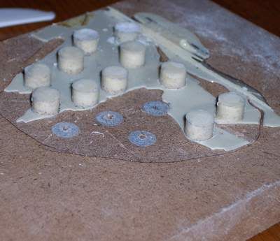
Started with a sheet of 1/4" Plexiglas with 3/8" holes drilled in it, and hot-melt-glued it to a sheet of MDF (medium density fiberboard):
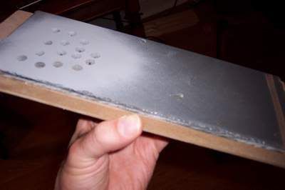
Before they were glued together, I held them together, sprayed some puffs of paint on the top to mark the circle locations on the MDF, and tapped some small finish nails through the centers of all the circles. The heads were chopped off by a Dremel tool, so they wouldn't get stuck in the caps, and the nails were all sunk into the MDF so they sat up about an eighth of an inch. Then the plexi was re-centered and glued onto the MDF:
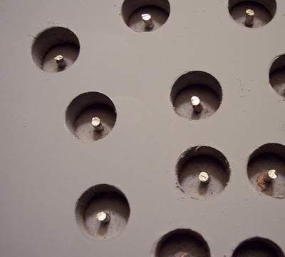
I sprayed it with some WD-40 (only thing I had on hand) and filled it with a mix of fiberglass resin, hardener, and a couple drops of white enamel paint (didn't know if they'd be painted later). When dry, I hit it with a belt sander to remove the excess:
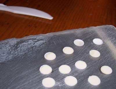
I pried the plexi away from the MDF to get this (after removing some buttons):
As you can see, the FG dripped under the MDF, so I had to snap away the edge to get them off:
 <-The one in the front has already been sanded.
They were lightly sanded to clean them up, by chucking them into the Dremel and holding paper against them (with gloves):
While still held in the chuck, I pulled each one off of it's nail and widened the nail holes with a drill bit and bit stop:
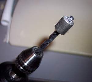
Some of the nails slipped a little, and let the caps spin, but ideally, they shouldn't need the spinning anyway. ;)
That's about it. :)
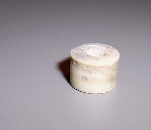
Here they are raw:
Then sprayed with gray primer and some clear lacquer, and permanently attached with a glob of JB Weld epoxy in the holes:
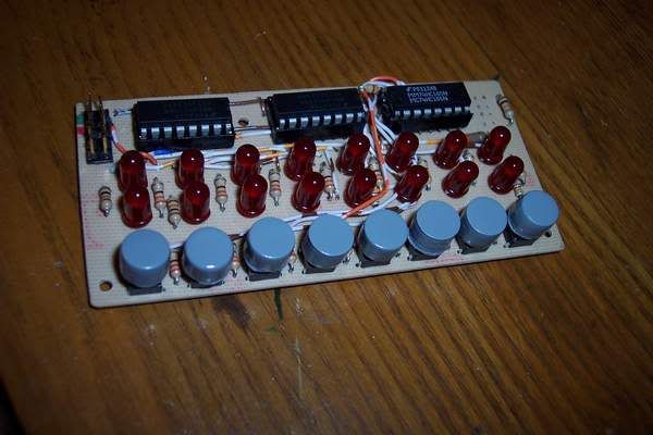
Sad, but I liked the board better with the raw switches. :'(
- the hell with it anyway ;D (I guess they'd look OK for something behind a panel)
-
Finally got this crap sorted out after a full day of finding shorts and missing lines. It's a DIN/DOUT board with 8 switches and 16 lights (apprx. 2"x4"):
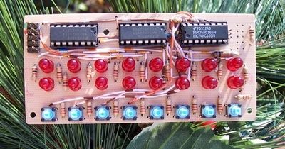
Here it is with one of it's hosts, a hybrid JDM/Core with custom headers:
George
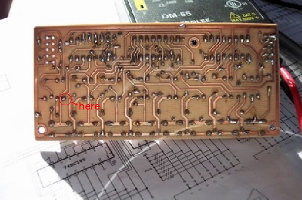
PS- Anybody ever slop something over their traces and jumpers to "freeze" them into position and protect them? Seriously though, I'm considering it. I figure once it works, there shouldn't be any need to access the stuff, and it's nice to be able to throw the things around without worrying about figuring out what you broke later on. Thought about fiberglass resin, silicone, and hot melt glue. Any ideas??
-
Still when you compare against similar speed and spec PCs, the Apples usually work out as the same price or cheaper.
Yeah, but very few people (especially not DIY'ers) will usually end up replacing full computers on each PC upgrade. With the Mac, you sort of have to. It was something I always dreaded and it never really got all that easy to swallow. My PCs tend to upgrade in sort of a "chunk" at a time, usually with MB/CPU combos being the biggie.
George
PS- Not meant as a "Mac vs. PC" comment, just pointing out an often overlooked detail. :)
I screwed up on the switch height.
in Parts Questions
Posted
You're saying just use the cut one to support the other? I thought of cutting a small scrap of plastic or something for that (don't know if it's worth wasting a switch). I really just don't like the idea of soldering wires to the legs. Seems sort of flimsy.
Thanks,
George
PS- Didn't actually order this stuff. It's been here a while from eBay rampages. ;D