

nebula
-
Posts
943 -
Joined
-
Last visited
-
Days Won
4
Content Type
Profiles
Forums
Blogs
Gallery
Posts posted by nebula
-
-
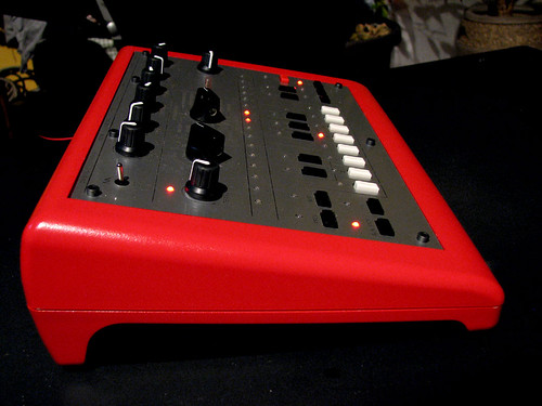
Your panel is just insanely gorgeous. I love it.
The Novation knobs in the first pic look really cool ... it would be really tempting to figure out a way to stick some frosted acrylic underneath the panel, peaking out from behind the knobs. You could light it up, creating a little illuminated halo around each knob. (But that would be a lot of very tedious work).
I've got the "Waldorf" knobs on my MB-6582, in grey. I find the grey ones a little "tamer" than the white / red ones you see in a lot of pics. The nicest ones IMHO are on Wilba's prototype, and are sadly no longer available.
-
Also consider participating in this bulk order.
The C64 PSU is a very elegant solution. It works very well.
-
I just etched a couple of OPL3 boards. I was planning on populating at least one next week. I'll let you know how it goes.
-
-
I now have a working x0xb0x! Peeeeeeooooooowwwww!!!
ISSUES
1. I had 10 mm spacers. I filed them down to 8 mm. They are not perfect, so it my panel is still slightly uneven. It's hardly noticable, but it is there when you look for it. I'll be buying some new spacers.
2. I think my square wave is a bit too sine-y. Back when I built the VCO the square didn't have that nice sharp point at the beginning of the cycle, it was slightly more rounded than the Ladyada oscilloscope screen shots. My square doesn't sound as bright as I think it should, and this is probably why. I'm going to look at Q8, C11, and some stuff around there. I don't remember right now, but I may have subbed a Tantalum in for C11 and some of the 1 uF caps instead of electrolytic.
BUILD TIPS:
1. First, let me repeat: MULTI-TURN trim pots. Next time I have my x0xb0x apart I am going to replace the VCO calibration trimmers and the power supply trimmer.
2. Don't spend too much time on VCO calibration when you're still at the VCO building phase. Get it close and move on, you'll need to calibrate it later. Ladyada's build site would have you inject 2V and 3V to get the VCO calibrated. The problem is, your actual CV generated might not be exactly 2V and 3V. My x0xb0x generates 1.98, 2.98, 3.97 and 4.95 on each "C". You'll never know the precise voltage you'll see until you fire it up with the atmega. I suppose you could remedy this somewhat by hand-matching all those 1% 200K resistors, which actually form the DAC in this project, but it's not really necessary unless you also want to interface with other 1V/oct control voltage devices.
3. If you use spacers under 10 mm (3/8") long, you will need to cut or file off the little protrusion on the side of the big encoders, or else they will get in the way of the sub-panel. Similarly, you will need to enlarge the holes where the toggle switch and Panasonic pots poke through. I used a machining bit on a Dremel and it made short work of the job, although it does of course make a mess :)
Now, if I may ....
HUGE thanks to Sasha and The Prof. You both remained dedicated to this project and made it really easy for a dolt like me to build this thing. Thanks for being there to support us, the builders too.
I decided to get in on this project only because I had a few extra bucks to burn. I have a pretty nice little home studio, and usually any time somebody came to visit they'd say something like "oh, wow! do you have a 303?" ... I would usually just sort of mumble some story about how the TB-303 was overrated in the first place, and it's played out ... and then show them something else I have that's more interesting. So the x0xb0x wasn't even really on my radar, until Sasha announced a pretty good price for boards and panels, with Dr. Pepper taking all the headache out of finding the rare parts. I figured "what the hell" and bit the bullet.
Am I ever glad I did! I have always thought the TB-303 to be more of a toy than a serious music machine. Now that I have had a x0xb0x for about 13 hours, I can honestly say that it's a surprisingly versatile instrument - not just for cheesy acid sounds! It also does really solid sub-bass parts, screaching leads, and other stuff too.
The really cool part the x0xb0x is that it can be sequenced via MIDI, so if you want swing timing, or just tighter DAW integration, it's there. I think I want 2 more.
Pics to follow.
EDIT: one thing I forgot to add... at first I thought Sasha's layout changes weren't all that important. Now that I'm using it, and I have this gorgeous front panel when compared to the adafruit x0x panels, I can honestly say that Sasha's changes are a significant improvement, and worth the deviation from Limor's design. Great job, Sasha!
-
I think it's expensive for a defective DX7. You should be able to get the price down.
I would:
Think of how much it would cost this person to get it fixed.
Subtract that from the current market value of a DX7.
Then take off about 25% and offer that.
The UK market for used keyboards is always a lot more pricey than North America though, so maybe the amount is right on the money.
-
Hmmm ... Now that I look at it more closely, I guess you're right about the reflection.
I'm not proposing enlarging any screw holes. I think I trimmed my pot shafts a little too short. To compensate, I can use shorter spacers, and then just enlarge the holes in the sub-panel around the Panasonic pots. It should make no difference, because those areas are generally covered by knobs anyway!
Also, on closer examination I see that the Grayhill encoders have a little "nub" that sticks up, which I can also file off. I'll try that first, but I'm confident now that I can work around this.
-
I should be clear here: I'm not upset or anything like that, and I'm not pointing fingers ... I'm just trying to find the solution for my problem.
I looked at this pic:
Maybe it's just me, but it seems to me that the black keys look like they don't stick out as much as the white keys. Am I wrong?
I have used shorter spacers than you, maybe because I trimmed the shafts too short. But my black keys stick out less than my white keys, and it's because I can't get the top part of the panel to sit as low as the bottom, due to the height of the Panasonic pots.
I am sure I can remedy this by enlarging the holes in the sub-panel. I am only posting to see if anybody else is having the same problem.
-
Hi Sasha,
I enlarged the hole for the toggle switch with a Dremel. Now the sub-panel touches the Panasonic pots before it reaches the spacers. I just looked more closely at your first x0xb0x and I see that the black keys don't stick out from the panel as much as the white keys ... it's because your panel is doing exactly the same thing. It is bending a little.
I think the solution would be to either use larger spacers (but then the pot shafts are too short), or else enlarge several holes in the sub-panel to accommodate for the taller housings on the Panasonic pots. I'm going to think about it.
Please let me know if I'm missing something.
Thanks!
-
As luck would have it, I had 7x 10mm aluminum hex spacers on hand. After assembling the panel against the board, I decided I needed 8 mm. (I cut my pot shafts fairly short I suppose, but it was suitable for the Sifam knobs).
Rather than ordering a set of 8 mm spacers, I filed my existing spacers down to 8 mm (+/- .5 mm).
Then I went to attach the panel. Unfortunately, the little square hole in the sub-panel for the toggle switch prevents the sub-panel from going low enough. So I think I'm going to remove a bit of material from the sub-panel. I might just hacksaw off that corner of the subpanel - after all, the corner of the main panel will still be supported by the PT-10.
-
Ordered these knobs from my good friends at "Hong Kong Super seller" ebay.
Do those knobs fit a D-shaft? It's hard to tell in the pic. Soundwell / Voti encoders have a "D" shaped shaft (i.e. one flat edge). Some knobs are meant for a spline shaft (ridged), and others have setscrews.
-
Well, an LED to show which sample is playing may or may not be doable. If you're talking about using the buttons to start AND stop samples, then yes, you could have an LED show that the sample was started but not stopped.
But if you are triggering one-shot samples in your laptop from a MIDIbox, the MIDIbox has no way of knowing how long the samples are, so the LED's on/off status would be meaningless.
I don't know how much experience you have with this type of stuff, so I'll add: don't take on a MIDIbox project to save money. You probably can't build something for less than it would cost to buy a cheap commercial controller off-the-shelf, especially if you need to buy basic hardware, tools, supplies and parts.
Advantages to building a MIDIbox (and DIY in general) are:
- customization (you can make it look and work exactly as you want it to)
- community (people in the forum will help you learn, so just by building you are contributing, and then you get bitten by the bug and want to help others, while other people learn from the help that you got), and
- pride (the satisfaction of realizing your own design, using it, and showing it off).
-
-
Thanks :)
Troubleshooting was easy. I didn't notice that the level coming from the VCF is much lower, so I needed to adjust my scope. Duh...
-
Another word to those building:
Most projects that use trim pots work best with multi-turn pots, similar to those used on the AOUT board variants. Sometimes, a single-turn pot works best, like for the brightness/contrast on a Core (where you don't really need ultra-fine control).
If you're sourcing parts, and you have a choice, use multi-turn pots for your x0xb0x. Having just calibrated my power supply and VCO, I can tell you that plain ol' cermet pots are a bloody nuisance, ESPECIALLY in the x0xb0x.
My status: I think I may get all the electronics done tonight, leaving only hardware issues (spacers etc) for tomorrow. My (completed) VCF section is not making a sound when tested according to the instructions on Ladyada's site, but I'm still trying to retrace my steps...
-
It's pretty, but I'm likely to spend more time with the familiar theme. I agree that it's nicer for reading in the dark. I wouldn't say the actual layout is significantly better or worse, but it's different enough that it takes me longer to navigate.
-
Maybe it's my inexperience so far with my MB-6582 so far, but I often find myself having to stop and think about which mod source is which when I assign something in the matrix. 1 and 2 are envelopes 1-2, and 3-8 are LFO 1-6. Usually when I create the modulation routing, I immediately want to jump to the modulation source and edit it. Unfortunately from a UI standpoint the matrix "feels" somewhat disconnected from the LFO and envelope controls.
At first I was thinking it would be nice for the modulation source to automatically be selected every time you create a modulation point, but that could be annoying if you're trying to tweak one source while toggling another. But...
It would be cool if I pressed "3" in the matrix, WITHOUT selecting a modulation target, and then RELEASED the button, the control surface would automatically change the selected LFO to #1. Maybe the newly selected LFO would even blink once or twice to show you that it did it. Or press and release "5" and the selected LFO would jump to 3. Or press and release "2" and the selected envelope would jump to 2.
The idea is that it saves the user a step, and some thought.
Similarly, when you select an LFO or an envelope using the selection buttons (LFO 1-6, Env 1-2), maybe the entire column in the matrix that corresponds to the source you select could blink, just once very quickly, to show which source you're about to edit.
Any opinions?
-
FWIW: the 7-pin "C64-style" jack isn't all that hard to find over here.
I got my 7-pin DIN jack from Digi-Key.
The one that I got was p/n 275-1021-ND. It's now a non-stock item but it still shows a minimum of 1 piece, so it would be worth phoning them about.
They also have a shielded version, part # 275-1026-ND, which should also work great. It's discontinued, 631 still in stock, $1.52 ea USD.
Other board-mount 7-pin sockets seem to differ in the spacing of the two front mounting pins. The other variation, with the more closely spaced front pins, are a bit more common, but you could probably just bend them or break them off and still be fine.
-
My second-last C64 power supply just bought it. Don't forget, if you're using an original Commodore "brick" power supply, do NOT LEAVE IT on a carpet! No air flow underneath = overheating = dead power supply.
So ... time to bump this thread ... I still hope to participate in this bulk order!
-
OK, I've been doing some more research... I think the most sensible approach would be to start with a really simple setup, with a core, a DIN module, and an LCD. If I order the parts as kits from Mike's shop along with a PIC with the bootloader included that should enable me to get my bearings and do some experimentation before I decide on how to proceed. With a single DIN module I can try out playing with both buttons and encoders with the 64E firmware, right?
I'm not sure if a version of the 64 or the 64E makes more sense really. In any case I'll start with a finished firmware before attempting to roll my own. Otherwise the learning curve will be too steep...
Personally, for live synth tweaking I prefer pots to encoders. Even pots that jump to the value of their position as soon as you move them. You get a far more tactile feel of what your parameter values are, because the knob has a pointer, and a definite "stop" at the minimum and maximum values. This is also the way the original PG-300 works (its pots are sliders).
For sitting down in the studio and programming patches, I prefer encoders to pots, because you can nudge parameter values a bit more intuitively, and you have finer control.
Encoders are connected to DIN modules, and pots are connected to AINs. A fully populated AIN (AINx4) module allows 32 pots. A fully populated DIN (DINx4) module accommodates 16 encoders.
-
Well... with my MB-6582 done (except for a case that won't close due to my long ribbons), I have started the plans for my next project, which is a simple standalone sequencer based on MB808. This is a bit of an experimental design, and it will really come together if I can figure out how to dedicate an encoder to the "rotate" function.
I don't need anybody to do it for me or anything, I'm quite keen to try, I am really looking for a go-ahead. To me it sounds easy, but just in case it would be extremely difficult, please tell me now, because I am designing a panel that will use this encoder.
Thanks!
-
Amazing. Thanks TK.
-
My next mold will have the buttons on top, and I will drill 1/16" holes through inconsequential parts of the mold to get a bit of air to it.
I am of course completely prepared to fail, so do you have any ideas where I should get bicomponent silicone? Or is there something I could use as a hardening agent for the silicone I'm using?
-
Like many here, I like the idea of using rubber buttons for on-the-fly, live programming. Love it or hate it, the Monome has made a splash ... its rubber buttons are ergonomic by virtue of the materials used, rather than its minimalist design. I have an Electribe ER-1 which just feels awesome under the fingers, so I want to build a percussion sequencer using MB-808 firmware and rubber buttons.
I have already started on panel layout, and I have some nifty ideas for how I'm going to put this whole thing together, but from what I've seen. making your own rubber buttons is entering into no-man's land. There have been one or two efforts from people here on the forum which have generally been abandoned.
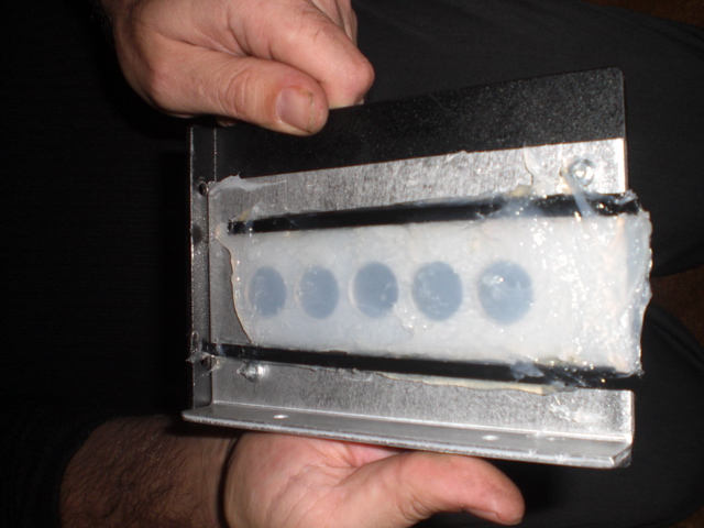
So ... here's what I've done so far: I used "GE Silicone II" which is a high-grade bathtub caulking. I chose it only because we use it a lot at my work, and I thought its rubbery consistency would translate nicely to panel buttons. I created a mold by drilling 11/16" holes in a piece of aluminum, about 3/16" thick, then putting a piece of textured, powder-coated steel beneath it, and fastening tightly with metal screws. This left some nice little wells to fill with silicone, which would be shaped like round buttons when extracted. The metal was from the scrap bin at my work. The extracted 11/16" buttons would be just slightly smaller than the 3/4" holes I would later drill in a panel.
In order to allow for a button membrane base, I suck a couple of tie-wraps (a.k.a. cable ties / zip ties) down at the edges of the mold with hot glue. This way I could fill up to the top of the tie-wraps and scrape off the excess with a knife.
Prior to squirting pouring in the silicone I sprayed the whole thing with "Pam" cooking spray. As I later learned, this stuff does a decent job of preventing the silicone from sticking to the mold - mostly.
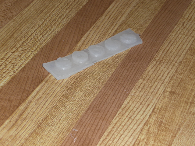
I allowed the stuff to cure for about a week and a half. As it turned out, this was not long enough for the silicone deeply inside the buttons to harden. When I pulled everything apart, the button tops were still gooey. As a result, the tops of the buttons are pitted and bumpy.
But the entire molded piece of five buttons is remarkably sound - I can bend it and manipulate it as much as I like, and the buttons have a solid but pleasant rubbery feel. Since I used the clear silicone, light passes through it pretty well. I will be able to light up each button with two bright LEDs. And I plan to put a 6 mm tactile switch (100 gram force) centred beneath each button.
This was my experiment. The next mold I make will be to fit my panel.
Of the pictures I took, the ones I'm attaching here are the only ones that make much sense.
C64 Power Supplies (110v/60hz version)
in Bulk Orders
Posted
Put it here:
http://www.midibox.org/dokuwiki/doku.php?id=dougwellington_mb6582_powersupply_bulk_order