Wilba
-
Posts
3,310 -
Joined
-
Last visited
-
Days Won
2
Content Type
Profiles
Forums
Blogs
Gallery
Everything posted by Wilba
-
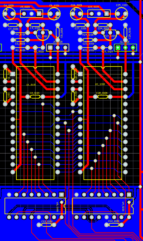
Here's a close-up of the revised PCB:

-
You might want to refer to what I did on my 8xSID PCB: http://www.midibox.org/dokuwiki/doku.php?id=wilba_mb_6582 You're right, they would share the same J2 connection, with separate SID:CS pin connections, essentially common data bus so SID registers can be set on either or both SIDs. It also then makes sense to use only two shift registers for each pair of SIDs, like what I did. You're welcome to copy as much as you like from my layout, it's as compact as you can get, and looks pretty neat with the common data bus arrangement.
-
8xSID MB-SID PCB (aka. MB-6582) - request for comments
Wilba replied to Wilba's topic in Bulk Orders
*** I removed this post because it was inappropriate *** -
Okay....finally going for a 1 voice midisid for now.....
Wilba replied to euphoricgrey's topic in MIDIbox SID
Yeah the "step C" control surface applies to one SID or many. Only the four "SID" buttons relate to having more than one SID, and it's best to leave them in your front panel design should you upgrade later and add more Core/SID modules. -
Until V2 is released, your only option is mono channels anyway. There is a V1 release that uses the PIC18F4685 so you can get those PICs now if you want. You will have no problems building a MB-SID V1 with PCBs, but if you have limited time, just build a single Core/SID... a multi-SID setup is possible but hard to test without a minimal "step B" control surface.
-
The values in the datasheets don't match what is in real C64s... the 22nF value was suggested to me originally by a HardSID user, confirmed as the actual value in C64 models with 8580, and backed up with audio tests and that formula, which proves it's a good optimization of cutoff frequency range vs. resolution. In short, 22nF gives you smoother bottom range than 6nF, if you want a smoother bottom range, then increase it to 47nF or 100nF. However, those caps I suggested are a great deal, you won't be disappointed ;D
-
MIDIbox of the Week (Wilba's MIDIbox SID V2, aka. MB-6582)
Wilba replied to TK.'s topic in MIDIbox of the Week
hahaha! So that's why I've had heaps of PMs lately! -
The filter caps control the filter's cutoff frequency. I don't know how different values of filter caps on one SID makes a difference to filter cutoff, it might just average between the two values, or maybe the cutoff frequency won't be stable... But when using two SIDs for stereo, if the cap values are different, you will notice the difference in cutoff frequency between them, which may cause phasing/stereo effects when you didn't want them.
-
8xSID MB-SID PCB (aka. MB-6582) - request for comments
Wilba replied to Wilba's topic in Bulk Orders
Can someone interested in buying the base PCB (and using 8580 or 6582) get some nice filter capacitors as described here: http://www.midibox.org/forum/index.php?topic=9132.msg64907#msg64907 and share them with the other people buying the base PCB and other MIDIbox SID builders? Surely there's someone in Europe who can send them around the rest of Europe for cheaper postage than me sending them all from Australia. Preferrably someone who can measure them with a multimeter and sort them by value, to find matched pairs with <1% tolerance! -
8xSID MB-SID PCB (aka. MB-6582) - request for comments
Wilba replied to Wilba's topic in Bulk Orders
No you don't need an AC power source for the SIDs, just 5v and 9v (for 8580 or 6582) and 12v (for 6581). -
8xSID MB-SID PCB (aka. MB-6582) - request for comments
Wilba replied to Wilba's topic in Bulk Orders
Oops... I just realised, the bezel is 9mm high, PCB is 1.6mm, gap is 10mm... so if you mount the LCD behind the CS PCB, there's a 2.6mm gap between LCD and frontpanel. Should still work fine, although maybe a slightly larger hole in the panel to compensate (i.e. so you can still see the bottom edge when viewed from a low angle). However, there is some good to come out of this... if mounting a display behind the CS PCB, you don't need those separate PCBs that sit above the display when it's mounted above the CS PCB, I can put those on the CS PCB itself. This makes manufacturing cheaper, the construction is a lot easier, and you can use the same switches throughout (13mm, no need for the 7mm ones). It also gives you the option to reduce the gap between CS PCB and panel to less than 10mm, if you really want to do that. For all those people wanting CS PCBs... let me know what your plans are (i.e. what knobs, encoders and display you want to use)... I can confirm it's all going to fit ;D -
8xSID MB-SID PCB (aka. MB-6582) - request for comments
Wilba replied to Wilba's topic in Bulk Orders
Discontinued? Arrgh! Well, it wasn't discontinued a few weeks ago... Must be a reliability problem or something, as both OSD and Winstar discontinued them... but they're still making other PLED/OLED products and revising their other PLED displays. Hmm... Luckily, I planned ahead and catered for this kind of situation. Those PLED displays are much thinner, and can squeeze into a 10mm gap (if you bend those little tabs on the back that hold the bezel, and route a little bit into the CS PCB to make one fat component fit). I say it's a squeeze because it really is tight. But at design time, I decided to handle the possibility that the display wouldn't fit (i.e. switch to a backlit LCD) so.... There's nothing routed where the display fits on the PCB, which gives people the ability to route a rectangluar hole the size of the display's bezel and mount the display so the bezel pokes through the CS PCB from behind. Typically the bezel is 9mm high, so it will be only 1mm behind the panel. Then those little PCBs that would normally sit above and below the display's PCB can sit above the CS PCB instead, they'll be held on with the same screws that hold the display to the CS PCB, and will need some spacers to support it when buttons are pressed. This solves the problem the neatest way... there's plenty of support from all those threaded spacers holding the PCB to the panel, so a big hole that big is not a problem. Increasing the gap between the panel and PCB is just too messy to deal with. ;) -
Comment about the interface: TK's finding it hard to come up with three letter acronyms for all the new parameters in MB-SID v2... so copying the "step A" interface might not be so good an idea if you're trying to display things like chord names in just three characters. You might want to start with the "step A" as a base, perhaps increase menu names/parameter names to four characters each (i.e. 2x20 display, four buttons, four menu/parameters per page). This will handle most of your parameters, things like "-128" aren't going to cause trouble. Then for things like chord names which might be better displayed with more than four characters, you could make it span across two items (i.e. over 9 characters) instead.
-
You might not need the DINx4 module, if you can make a DINx1 on a breadboard, and you could even use PIC pins to drive the switches. I'd suggest using a 4066 to drive the switches. If I had the need to do something like this, I'd probably go one step further and not bother using MIOS at all... just write some custom code for a PIC16F88 or something similar, and cut it down to just a small PIC and a 4066, driving both off the internal +5v supply. But if you have plans to do anything more than drive two switches from one encoder (or can't program assember that well), you should stick to using MIOS.
-
8xSID MB-SID PCB (aka. MB-6582) - request for comments
Wilba replied to Wilba's topic in Bulk Orders
I totally underestimated how many people would want the control surface PCBs too! I'll expand this thread to include discussions about the CS PCBs also... Just so you know, I am NOT selling "kits", so if you want to use the control surface PCBs then you will have to find the parts that suit. However, I am willing to get some 100x packs of the switches you need and distribute them with control surface PCBs, since they're cheap and the most specific thing you need for the PCBs. Also, some of the 100mil spacing ribbon cable, this stuff is heavy duty and a lot stiffer than normal ribbon cable, which makes it harder to close the case ;) but also more tolerant of opening/closing the case a lot... it's rare stuff and I have too much of it so I'll share it around too... The control surface PCBs are designed to work with the following parts: #0: 35x ALPS tactile switches, 13mm tall, AND 13x ALPS tactile switches, 7mm tall The control surface PCBs and front panel are designed around these switches. They snap into the PCB holes and are thus perfectly aligned with the panel, and poke out 1.5mm from the top of the panel, making for a neat finish. #1: A display that fits between the PCB and panel, and a 4x20 LED backlight LCD will NOT FIT, unless you do some routing of the PCB and mount it behind the PCB. MAYBE a 4x20 "edge-lit" LED backlight LCD might fit... there's a 10mm gap between panel and PCB. For best results, get what I have, a 4x20 PLED from One Stop Displays (OSD), part number OSD2004M01. http://www.osddisplays.com/pled.php #2: 3mm LEDs. It is probably best to measure the LEDs you get before ordering your panel, just in case the LEDs aren't exactly 3mm, you can adjust the hole sizes to suit. #3: Rotary Encoders. I use some that are like ALPS STEC16B, they are the ones that Voti sell, but I didn't get them from Voti, I got them direct from Electronics China. If you look closely on the PCB, you'll see there's provision for smaller encoders with a different pinout, but they might not be the right height. #4: Knobs. I'm using the "Waldorf" knobs from ALBS.de (just like TK!) and these nicely cover the threaded bushings on the encoders that poke through above the panel by 1.5mm. part #863062, "Drehknopf DK16-190V3 A.6/4,5 AT=14,5 schwarz soft-transparent rot TR-3925" http://www.albs.de/ecom/images/863062.pdf #5: Case. The PT-10 from PacTec. If you want this control surface, there's no point using any other case. (Well, that's my opinion anyway. You don't have to use the PT-10 and it might be fun to see someone use this in a huge rackmount case, or in some other construction with wood endcheeks ot something.) The panels are 1.5mm, you can order them yourself and modify the artwork, or lazertran on top, whatever you like. As I described in the blog, the best way to solder the control surface PCBs is by using the front panel as a guide, especially for soldering the LEDs in perfect alignment. There's also the "trick" of gluing four flat-head screws and 10mm threaded spacers to the panel using JB-Weld. It's not particularly hard to do, but you will need JB-Weld and four little G-clamps to assist. OK, that's it... people who want control surface PCBs now know what they need... you can ask me any questions you like about it, and I'll probably write up proper instructions you can follow... it's not that hard to put together once you follow a certain order of construction, and the hardest part is actually assembling the two little PCBs above/below the display... you can sort of see it in this shot... ... those two little PCBs are held in place with the same screws that go through the display mount holes, and through the control surface PCB (with nuts on the underside)... anyway, you'll find out how tricky that part is when you come to it... ;D -
8xSID MB-SID PCB (aka. MB-6582) - request for comments
Wilba replied to Wilba's topic in Bulk Orders
The switch on the PCB is a DPDT I think, stryd can confirm, he knows switches... but it's effectively just two toggle switches in parallel, so one switches the 9v AC current and the other switches the 5v DC current. If supplying power externally, you can either go in through the pads for the C64 power socket (i.e. supply 9v AC/5v regulated DC) and choose to use the C64 power switch (or mount an alternative switch there), OR supply power into a SIL header, and put the switch on the mains end of the PSU... in which case that switch might be embedded in the PSU anyway or you'll want a heavy duty panel mount one and don't care about the one on the PCB. So I don't really know if that answers your question... but I can definitely confirm I'm not changing the power supply RAILS on the board itself - just the circuit before the 5v/9v/12v rails start. -
8xSID MB-SID PCB (aka. MB-6582) - request for comments
Wilba replied to Wilba's topic in Bulk Orders
I'm only arranging a batch order of the base PCB, not the control surface PCBs. I don't think many people would want to make a control surface exactly like mine. The only problem with getting the control surface PCB is that you're stuck with the exact same parts I used, which might not suit your style or budget... two different kinds of ALPS tactile switches, knobs from ALBS.de, 4x20 PLED display, 1.5mm anodized aluminium panel from Front Panel Express (or Schaeffer)... etc. But I'm not stopping anyone to make one exactly like mine... I could get a couple more made if there's at least two people wanting them... OK it seems pretty settled that there's enough interest in the base PCB, so I'll see what prices I can get for a batch. -
Wow. Took me a while to realise this is Tetris and not just some pretty flashy lights. Do you mean like Game of Life? I love the hypnocube too but I'm too much of a hacker to be satisfied with just looking at the pre-made patterns.... I want to make my own, but it's all very closed-source.... bit of a shame really because it seems so logical to make it open source and generate a hacker community around it, instead of just a bunch of non-hackers who want to upgrade their lava lamps. And I also have typical envy of their next generation 8x8x8 cube, way out of my price range for a toy that just looks pretty and I can't tinker with.
-
8xSID MB-SID PCB (aka. MB-6582) - request for comments
Wilba replied to Wilba's topic in Bulk Orders
That one's probably a bit too big... I could probably do a SIL socket, but I don't know what's the preferred inputs. I guess I need a case example of someone who used their own transformers and PSU circuit (there's a lot of them in the gallery!)... so how best to plug into and use the regulators on the PCB (including adding space for an optional 5v regulator). There's enough room with the IIC MIDI modules now removed to do something quite flexible, I just don't know what an alternative PSU would look like. -
8xSID MB-SID PCB (aka. MB-6582) - request for comments
Wilba replied to Wilba's topic in Bulk Orders
You've got a DINx5 and DOUTx3 to play with. That's enough for 16 encoders + 64 buttons + 128 LEDs. -
MIDIbox of the Week (Wilba's MIDIbox SID V2, aka. MB-6582)
Wilba replied to TK.'s topic in MIDIbox of the Week
Topic for discussing the MB-6582 Base PCB revision/ordering: http://www.midibox.org/forum/index.php?topic=9238 -
Topic for discussing the MB-6582 Base PCB revision/ordering: http://www.midibox.org/forum/index.php?topic=9238
-
This thread is closed, move to this thread for more relevant information: http://www.midibox.org/forum/index.php?topic=9560 *************** This thread is for those people wishing to buy and use the PCB I designed for my MB-6582 MIDIbox SID Synth project, i.e. an all-in-one board for 4x Core, 8x SID, 8x BankStick, 5xDIN, 3xDOUT If you don't know what I'm talking about, here are the links: MIDIbox of the Week (Wilba's MIDIbox SID V2, aka. MB-6582) MB-6582 - an 8xSID MB-SID synth MB-6582 Wiki So rather than just release the exact PCB files that I used for my box, I am doing a few minor changes now that the MB-SID V2 hardware changes are (to my knowledge) final. In other words, PIC18F4620 is no longer to be used, so IIC MIDI modules are now not needed (rip 'em out!) and PIC18F4685 is now to be used, so add the CAN bus to link all the PICs in a super-fast MIDIbox Network. Also, rather than answer the same question over and over, I'll make some statements now to answer any questions: * The "Base PCB" is essentially a merging of multiple MIDIbox modules into one compact PCB, and should work exactly the same as connecting multiple MIDIbox modules with cables. * The original "Base PCB" has a 9v supply to all 8 SIDs. The revised "Base PCB" will have 9v and 12v supply rails which you can connect to a pair of SIDs, so each pair of SIDs can be either 6581 SIDs or 8580/6582 SIDs. * You don't have to use all the SID sockets. You can choose to put SIDs in stereo pairs, or only put a SID in the left SID socket for a mono channel. * You don't have to use all the PIC sockets. You can choose to use less than four PICs. * You don't have to use the DIN/DOUT at the bottom of the PCB, and you don't have to use the optimized switch/LED matrix I designed to get a "step C" control surface with only 8 shift registers, and you don't have to use a "step C" control surface (or any control surface). However, TK has kindly done all the code changes to support the optimized switch/LED matrix so you can have a big control surface with only the shift registers on this PCB. * Final cost will be a maximum of US$50 if two people split a prototype PCB order from Gold Phoenix (where I got mine made). This would become cheaper if I organize a batch order and sell them, but I'm not going to do that unless there's enough people wanting one. * the base PCB is exactly 9200mil x 7215mil (9.2 inches x 7.215 inches). This fits exactly into the PT-10 case by PacTec, with mount holes that line up with the case standoffs. OK, now for the "request for comments": * The PCB uses the original C64 power socket and C64 power switch, and uses the original C64 PSU (external transformer). If you are not going to use these components, what are you going to use? How best can I support your use of a different power supply? * Do you have any other suggestions to make?
-
Well he said he had it working when pressing two at the same time... so maybe it will work fine... in my case I had a custom DINx4 PCB with all 32 inputs being used as a touch sensor... imagine a lot of thick copper wires being used to simulate four strings on a guitar, i.e. they were as long as a fret spacing, so four rows of eight sensors. I recall I was getting heaps of false triggering... now it could be that the load was too much, so that sensors other than the one I touched weren't being held high... I don't really know why it wasn't working (otherwise I would have fixed it!)
-
The rest of the application will work whether the switches are touch sensors (with the 47k resistor connected to J14) or normal switches (with 10k pull up resistors). Increasing the 47k will reduce the current getting to the shift register pin and it might not be enough to be sensed as a logic high when untouched. The code to turn on the touch sensor function is trivial. This is what usually appears in the MIOS_USER_Init routine: movlw 0x00 ; disable touch sensor call MIOS_SRIO_TS_SensitivitySet [/code] Change 0x00 to some bigger number. AFAIK this controls the duration of the pulse on J14, which controls how sensitive the touch sensor is... if it's a long pulse, I think you need to touch the sensor harder so your finger conducts more and stores the charge. You might also want to call MIOS_SRIO_DebounceSet in a similar way. Have fun experimenting, but don't get too disappointed if it doesn't work well for you... i.e. there's probably going to be a lot of bounce on those triggers so