Wilba
-
Posts
3,310 -
Joined
-
Last visited
-
Days Won
2
Content Type
Profiles
Forums
Blogs
Gallery
Everything posted by Wilba
-
Something is wrong if you get 10v at the C64 plug, with it disconnected... It should be 9v AC and 5v DC.
-
Test the 5v output of the C64 PSU without connecting to anything... i.e. test pins of the DIN plug.
-
more than likely the problem is 4-bit mode... my tests show that after each command it sends, it gets back a status byte, and sometimes the two 4-bit nibbles are in the wrong order, so depending on the cursor address, MIOS thinks it stays busy until a timeout is reached. I've written a custom LCD driver that uses 8-bit mode by using two pins on port E to replace the two pins being used by the CAN... you'll need to add wires and ensure D0 and D1 are still connected to port B pins, and D2 and D3 connect to port E1 and E2. http://www.midibox.org/dokuwiki/doku.php?id=pic18f4685_8bit_lcd_driver This solves the problem with my 4x20 PLED and have not had a problem since.
-
Yes, very nice work! I am interested in those Multimec switches, they look really nice.
-
If you're sampling from Microchip, you can get 3x PIC18F4658-E/P and 3x PIC18F4658-I/P and also 3x 24LC512 (PDIP package)... you can also donate any unused PICs to others here. I have sampled before, but I also bought their PIC burner so I don't feel guilty ;D and I suppose I've generated some demand for their chips by making a PCB that needs 12 of them!
-
8xSID MB-SID PCB (aka. MB-6582) - request for comments
Wilba replied to Wilba's topic in Bulk Orders
I said you won't find PLEDs anymore. You will find LCDs on eBay. Search for "20x4 LCD" Something like this *** Sorry this is taking so long, I discovered last night that SmashTV uses 6-pin resistor networks in his DIN module and I used 5-pin. So I made changes to support both 5-pin and 6-pin (mainly because SmashTV has 6-pin, and might offer a "bag of bits" to go with the PCB), and then discovered I was missing those resistors that hold the signal high if you don't stuff all the shift registers... i.e. they make a DINx4 board work with only one shift register, so for completeness I've put those resistors in. And to annoy you even more with delays, I'm going on a business trip next week and won't be doing anything for two weeks. So I wouldn't be expecting delivery of any PCBs until mid-July at the earliest. -
Yeah should work fine, you just want to keep it big so you're not affecting the audio output as it goes into whatever you use to amplify it.
-
I'm still interested in the website though... other people want these PICs too.
-
Post a link to the website... It's usually "-I/P" or "-E/P". First letter means temp. range, either is fine ("I" = Industrial, -40 to +85). Letters after the slash are package, "P"=PDIP, you don't want any of the others. It should be 40 pins (leads/legs).
-
8xSID MB-SID PCB (aka. MB-6582) - request for comments
Wilba replied to Wilba's topic in Bulk Orders
Those ones aren't PLED, and they've got different dimensions anyway. Basically there are PLEDs, and then there are LCD with different kinds of backlight (edge-lit, LED array behind, EL, etc). With PLEDs, each pixel is an LED. With LCD, each pixel is a little black square of LCD (or the absence of a little black square in inverted displays). The control surface PCB will suit an "industry standard" 20x4 (4x20) character display. Something like this one is as close as you can get to the PLED I used: http://www.crystalfontz.com/products/2004a-color/index.html#CFAH2004AYTIJP You need one with mounting holes that match the PCB, i.e. 93mm horizontal, 55mm vertical, 2.5mm diameter, and the "Active Area (AA)" where the character pixels are is a rectangle of 70.4mm x 20.8mm which is centred. eBay will have plenty if you can't afford Crystalfontz, and there's nothing wrong with using a common black-on-green LCD like many other people, with red LEDs this will look hot with a white-on-black panel, much like this one: http://www.midibox.org/forum/index.php?topic=7438.0 I will adjust the size of the hole in the panel so that if the display is a few millimeters behind the panel then you don't cover up the bottom edge if viewed from a low angle. It really shouldn't make any difference then whether the display was flush with the panel or not, and might even look cool. If you mount the display behind the PCB, the top of the display will be 9mm - 1.6mm = 7.4mm above the PCB. The gap between PCB and front panel is 10mm, so the top of the display is 2.6mm behind the front panel. The front panel is 1.5mm thick, so it's 4.1mm behind the front panel's front surface. So... to make the "View Area (VA)" entirely visible at 45 degrees, you just use a hole with the same dimensions as the view area, plus 4.1mm around the edge. eg. the "View Area (VA)" is 75mm x 24.2mm, so make it 83.2mm x 32.4mm *** I'm not sure whether it's a good idea to start ordering panels yet, because MB-SID V2 is not finished and I made my panel knowing it wouldn't be perfect... already some of my "extras" are wrong... so while I can understand everyone is eager to get started, what I might suggest is we arrange a control surface PCB order a bit later, and get the base PCB order started very soon so those people wanting just the base PCB don't have to wait around for me to tinker with the control surface design or wait until MB-SID V2 is nearly released. The base PCB is compatible with the MB-SID v1.74685 release and people can hack together a "step A" or "step B" control surface to play with it, or just use JSynthLib. People wanting both PCBs can get both delivered later to save postage if they really want, or get their base PCB now and start soldering. I'm just saying that it's probably a good idea to wait a little longer before ordering panels and matching control surface PCB. BTW the base PCB revisions are complete, I just have to get some quotes. -
It's a bit of a trade-off... PCB modules are easier to troubleshoot, but sometimes the "trouble" is due to the wiring between the modules, or building the extra bits that don't come on a pre-made PCB. eg. to make a multi-SID MIDIbox SID, this usually involves making a custom PSU circuit to reuse an original C64 PSU transformer, and a PCB for one or more BankSticks (IIC EEPROM) to store patches. When the "MB-6582" PCBs are ready, I'll make a construction guide and you can do things in stages, this avoids the need to troubleshoot when everything is already soldered and connected, and in most cases, swapping PIC and SID chips can diagnose if either of them are not working. The "MB-6582" base PCB is probably not too big a project for someone who's soldered before, who understands electronics, knows how to use a multimeter to test for good soldering joints and no short circuits... but if you're interested in building other MIDIbox stuff too, get a Core and a DIN module and practice on that first, make a mini-MIDI controller with 8 knobs or something. You can always turn it into something else later. The encoders on MIDIbox SID "step C" control surface are dedicated to controlling the synth. If you are wanting some extra encoders and sliders in the same case to work like MIDI controllers, then it wouldn't be too hard for an experienced PIC ASM coder to make those changes to the firmware... and it is easy to add another DIN module for adding more encoders. So it's all up to you really... it's not too hard to solder the "MB-6582" base PCB, it's less work than making your own C64 PSU circuit and BankStick circuit on prototyping board, no chance of wiring errors between "modules" or in the C64 PSU circuit or BankStick circuit. I can't guarantee you won't have some problem that needs fixing, but I can guarantee it's not that much harder to work out what's wrong if you build and test things in stages. If you're still undecided, get a Core kit now and get some soldering practice in, get things like MIOS Studio working, connect an LCD display... all these bits can be reused in a second MIDIbox controller.
-
8xSID MB-SID PCB (aka. MB-6582) - request for comments
Wilba replied to Wilba's topic in Bulk Orders
As far as I'm aware, a C64 PSU "brick" should deliver enough 5V current to power an LCD backlight. Also, those "edge-lit" ones (anything with white LEDs) use much less current. Since a standard LCD with backlight is >10mm thick, it won't fit in a 10mm gap like I use, so the easiest solution is just mount it behind the control surface PCB. This means the display will be a little further behind the panel than on mine, but you won't have to deal with those two little PCBs that I use. So I've changed the PCB so that those switches and LEDs which were on separate PCBs are now on the CS PCB, and users are expected to cut a hole in the PCB with a rotary tool (Dremel) so their display fits through. (If this is a problem for some people then I'll do it for you!) If you really don't like a few millimeters of gap between the panel and the display, then you can possibly reduce the gap with shorter threaded spacers, but then the rotary encoders might poke through more than you want, this can offset this by using a thicker panel, but then you might need longer tactile switches, etc... ;) It's hard to get display, switches, LEDs and encoders all to fit into a single-PCB design... so I'm catering for most people by "supporting" a standard thickness 4x20 backlit LCD and not requiring those extra PCBs. -
8xSID MB-SID PCB (aka. MB-6582) - request for comments
Wilba replied to Wilba's topic in Bulk Orders
Frontpanel was by Front Panel Express. You could get it made by Schaeffer like a lot of other MIDIboxers. I haven't released the FPD files yet, I really should upload them somewhere for people to start playing with them... For MB-SID V2, you can control two SIDs per PIC, ideally these should be the same kind of SID, so for stereo, they'll sound the same. So it's probably best to put same SIDs together in pairs, but you are not restricted to this on the revised PCB. Each SID can connect to 12v or 9v. It was easier to use two separate headers with jumper. I am very busy making the revisions now, once they are done I can get some made and then build up a list of parts (i.e. C1 = 2200 uF electro, etc.) The schematics are a bit of a mess actually, but you won't need schematics, in most cases it all matches the MIDIbox module schematics and port pinouts. It's not "best" to use 8 similar ones. It's "best" to use similar ones in pairs. Jumpers control the different voltage, you can use machine pin sockets for swappable filter capacitors, and the firmware can be recompiled for 8580 or 6581 (and possibly will not need this in V2, just change in config). -
I don't know what you mean exactly... As far as I know, Core:J10:SC is not being used by the SID module. So, cut the track between Core:J10:SC and PIC pin 22, and connect Core:J10:SC to PIC pin 27 with wire. Then on the Dual-SID module, that pin goes to second SID's CS pin. Other people with two SID modules can also do the same thing, and modify the second SID module so the SID:J2:SC connects to SID's CS pin, and break track between SID:J2:SO and SID's CS pin.
-
8xSID MB-SID PCB (aka. MB-6582) - request for comments
Wilba replied to Wilba's topic in Bulk Orders
I'm not an audio expert, I don't know the difference between distortion and overdrive.... ??? The four knobs at the back control dual-gang 500k pots, the audio output of each SID goes to one side, ground on the other side, wiper goes to audio input of the SID. So basic voltage-divide, volume control thing, to control how much "feedback" to use. With filtering the external input, you get more resonance (and self-oscillation) when using bandpass. With filtering externa input turned off, it's distortion. Amplified and clipped. That's all. Each SID has a three-pin header with Audio In/Gnd/Audio Out, if you don't use the feeback pots, you ground Audio In with jumper, or if you want to use feedback pots, you connect wires between the pot and that header. That header is in addition to the stereo sockets for audio output. -
That will just blue shift it ;D ;D
-
8xSID MB-SID PCB (aka. MB-6582) - request for comments
Wilba replied to Wilba's topic in Bulk Orders
I've redesigned the ports around each Core, there's now J6/J7 SIL headers which are together (so you can use IDC connector like SmashTV's Core PCB) so each PIC can drive its own AOUT module through that port. On my box, I'm routing all four AOUT controls to the 25-pin DSUB at the back, should I ever have (need) four external filters/VCAs. -
8xSID MB-SID PCB (aka. MB-6582) - request for comments
Wilba replied to Wilba's topic in Bulk Orders
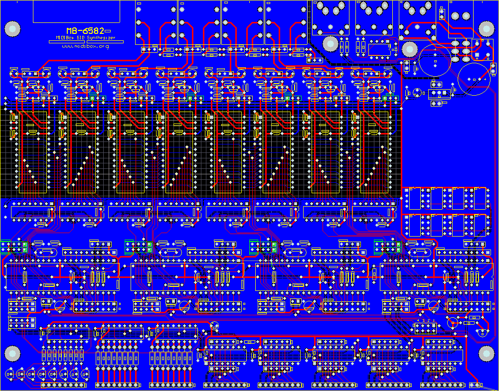
NorthernLightX: some others are already getting those caps, so you should deal with one of them, I'm sure they'll have plenty to spare. They're preferrable only because they're 1% tolerance, even less if you sort by value, and you can solder them if you really want, they're not fragile like styroflex ones. There's no need to throw in extra cash, I am essentially donating the PCB designs to the MIDIbox community, and I will arrange some PCB manufacturing. However, if you would like to sell me some MAX525 and MAX6007 to make some AOUT boards that would be cool... I have four CEM3379 filter chips which I'd like to turn into two stereo filters/VCAs so I need four MAX525 (and maybe only one MAX6007). As for powering the PCB... there's definitely going to be a nice SIL header for supplying +12v/+9v/+5v/Gnd (i.e. where the regulators would normally output) as well as an alternative to the PCB mount DIN socket that the C64 uses. The tricky bit that I'm working out now is giving people the option to just regulate the 9v AC with one 7809 (like in my PCB) or add it to the 5v DC for 12v (and also 9v if you need it). As you can see in this snapshot, there's heaps of room to please everyone ;D
-
I wasn't asking "why give it a name", only asking about the name you chose. I agree with you on the point of identity and personal aesthetic touch, that's why I spent the time to make a nice looking box ;D and give it a name like MB-6582 ;)
-
Yes, you'll need to use the "unused" pin on SID module's J2 port to connect to the PIC's pin 27 (Core J14). This will mean a bit of a change on the Core module PCB to connect PIC pin 27 to Core's J10 port. I must also strongly advice to separate digital and analog grounds on this module, i.e. connect the SID's ground to the same ground as the audio buffers, audio output and 7809 or 7812 ground pin. Use a separate ground connection for 74HC595 (connected to ground on the J2 port). A separate 5V connection to the SID would also be a good idea, i.e. connect the 74HC595 5V to J2 port, and have a separate 5V connection to the SID, which you can connect to J2 port if you want, or connect with separate wiring to the PSU. This will minimize digital noise on the 5V supply coming out the audio output.
-
Ma Bell I Got The Ill Communication
-
OK, so why did you call it Endorphin?
-
Yeah I am only using 6582... you need to turn on bandpass and Ext In (i.e. filter external input) to get anything interesting... the 6581 filter is different so may not achieve self-oscillation or have too weak resonance, I don't really know much about that.
-
8xSID MB-SID PCB (aka. MB-6582) - request for comments
Wilba replied to Wilba's topic in Bulk Orders
*** I removed this post because it was inappropriate *** -
Yeah, I totally didn't expect that! As for EAGLE, I just used what I had available... and it was way too big for the free version of EAGLE.