

Wilba
-
Posts
3,310 -
Joined
-
Last visited
-
Days Won
2
Content Type
Profiles
Forums
Blogs
Gallery
Posts posted by Wilba
-
-
Excellent work... I like how you have used PCB mounted sockets.
How did you do the artwork on the frontpanel?
-
I agree it's annoying.
-
It sounds like it was OK, then you took the CS board off and installed chips and when it was put together again, you have LCD and switch problems.
Or possibly voltage issues, now that you're powering two SIDs.
SO I would say, revert back to the way it was first. Take out the SIDs and 24LC512 ICs (I would suggest numbering the 24LC512 ICs with a pencil so you can put them back the same).
Also check you have the shunts set correctly for the high-power LCD and turn the brightness knob to minimum. This will help you assess if it's a current draw problem.
Upload firmware again (with CS PCB removed!) to be sure the PIC is still working and that you SHOULD be seeing stuff on the LCD.
Then you can reassemble and it will probably work again. Then you can see it stop working by increasing the LCD brightness and/or inserting the SIDs, and then prove it's a current supply issue and not anything to do with shorts/breaks/bad joints.
-
This might not be relevant, but sometimes my MIDI interface is in loopback mode, where it echoes MIDI In to MIDI Out... if a MIDIbox is connected when this happens, the upload request gets sent back to the MIDIbox and it stays in "black bars" mode.
At this point I'd have to point the finger at your PC/MIDI interface being the problem.
Try MIOS Studio 2 and see if that makes a difference, it could just be the fairly common "bugs" of MIOS Studio 1 (crappy Java MIDI library).
-
Hi nILS,
My boards didn't arrive today.
You suck at the bulk order madness.
:frantics: :frantics: :frantics:
-
Oh yes, sorry about that. I did check that as well i powered it on, and took a reading from 12V rail to the 12V labeled places on the diagran, with 20 on my multimeter. It gave 0,33V. So, is there something wrong with my voltage regulators? I used non-conductive thermal compound, and check the pins as well. There's no connection between them, or the heatsink (or at least it didn't beep). Thank you for the advices.
Edit: Ok, fixed on issue. now the reading of one probe on 12V rail and the other on other 12V place/9V place is little over 11V. Does that mean the regulators work and the problem is elsewhere? i tried soldering dc-socket again, but didn't help. I suppose the two pins have to be connected. Any suggestions how do i start looking for the possible 5V and GND shortage?
You need to test voltages with the black (common) probe on ground, and the red probe on what you're testing.
Please repeat the voltage tests, and report what the voltage is for the 9V pins, and ALSO what the voltage is going into the 7805 (the left pin of the 7805)... this will be less than 9V because it passes through two diodes. If there's no voltage (or insufficient voltage) going into the 7805 then it won't output 5V.
Still assuming that the 7805 should be working, then the problem is still (perhaps) a short between 5V and ground, so check solder joints wherever there are 5V and ground pins in close proximity. There are a lot of these under the 24LC512 ICs (aka. the "Banksticks").
-
My best guess at present is a short between 5V and ground somewhere... could be between 9V and ground (you didn't report if the 9V was good).
You should check nothing is shorting on the voltage regulator pins, perhaps the heatsink is touching the pins, or you used conductive thermal compound instead of the non-conductive (silicone) kind.
It's probably not a good idea to leave it on for very long while it's like this, it might blow the 7805.
-
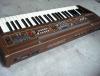
POIDH! (I know they mostly look the same, but it's nice to see photos next to your other gear!)
-
What he said.
Check your multimeter is working first. "2000m DCV" suggests you haven't set the multimeter to a good range, like 20 volts. 2000mV is just 2 volts, anything higher than that and the measurement is invalid, perhaps even showing "0" on the display.
Then start with testing the power supply is outputting anything, then measure what is labelled as "12V" on the voltage test diagram, it might be higher or lower than 12V but should be at least 10.5V to make the 9V regulator work well.
-
I see no MIDI ports here... :unsure:
-
Here's a ghetto fix for you...
You should be able to replace the pot in the pitch bend to something larger. Let's assume the master tune pot is really 100K. You want something that has 100K in 40% of the pitch bend wheel sweep, so 250K linear pot.
Now you can open up the pot, there'll be a resistive strip, an arc of carbon paint with a wiper on it. You can then (somehow) "short" the 30% on either side of the middle 40%... make that part of the strip very low resistance. It might take a bit of trial and error to get it working correctly, and maybe you need to tweak the "middle" position of the pot relative to the pitch wheel mid point (where it springs back to)... but it should work, and is pretty cheap
Check this out:
http://www.geofex.com/article_folders/potsecrets/potscret.htm
you can bridge over breaks in the resistive material with copper or silver conductive paint, or make a custom tap pointOK now that would be the 1:1 solution... a pseudo-100K pot in a pitch wheel. However, if it really is a linear pot, it might just be being used as a voltage divider and some other trick might work better.
-
19.22V at J20 is wrong. That should be regulated at exactly 9V by the 7809 voltage regulator.
I am assuming you (correctly) did not install shunts at JBP and have the shunt at JP set horizontal (8580/6582).
I am not aware of any way that regulated 12V DC going into a 7809 can produce 19.22V.
What kind of walwart are you using? If it is a switchmode, then perhaps that explains the voltage strangeness.
Also, check your multimeter is correctly measuring voltage. If this walwart outputs 12V then you should measure this first.
Measure all the other points as described in the voltage tests... especially the voltage going into the 7809.
We can work on the MIDI In issue after you get sensible voltages... perhaps this is also the cause of the MIDI In not working, the PIC isn't getting a stable voltage or the MIDI circuit is failing due to voltage not being stable.
-
-
-
btw if you're interested, I can give you a spare control surface PCB (one of the black prototypes).
-
You are correct.
Sorry I don't have a schematic publishable at the moment.
It should be easy enough to work out the pin assignments... most tracks are on the top layer.
Just remember that the left side is a MIRROR of the right.
i.e. D0->R1->LED anodes of two MIDDLE columns of three LEDs.
D7->R8->LED anodes of two OUTER columns of three LEDs.
http://midibox.org/forums/index.php?app=gallery&module=images§ion=viewimage&img=37
-
This VCA is a good workaround to the SID ADSR bug... you just set the oscillators to A=0 D=0 S=15 R=0 and control volume through the SID engine's envelope.
Well actually you are not limited to just Env->Vol modulation... you can do whatever you like in the mod matrix and modulate volume. There's even a parameter to switch whether volume modulation will modulate the SID's internal 4-bit volume control or an external analog VCA.
V2A (Volume to Analog): Volumes are forwarded to external CV outputs as well (assignments have to be done in the setup_*.asm file). Note that the effective volume value behind the modulation path is taken - accordingly you are able to realize an external VCA to overcome the ADSR bug. -
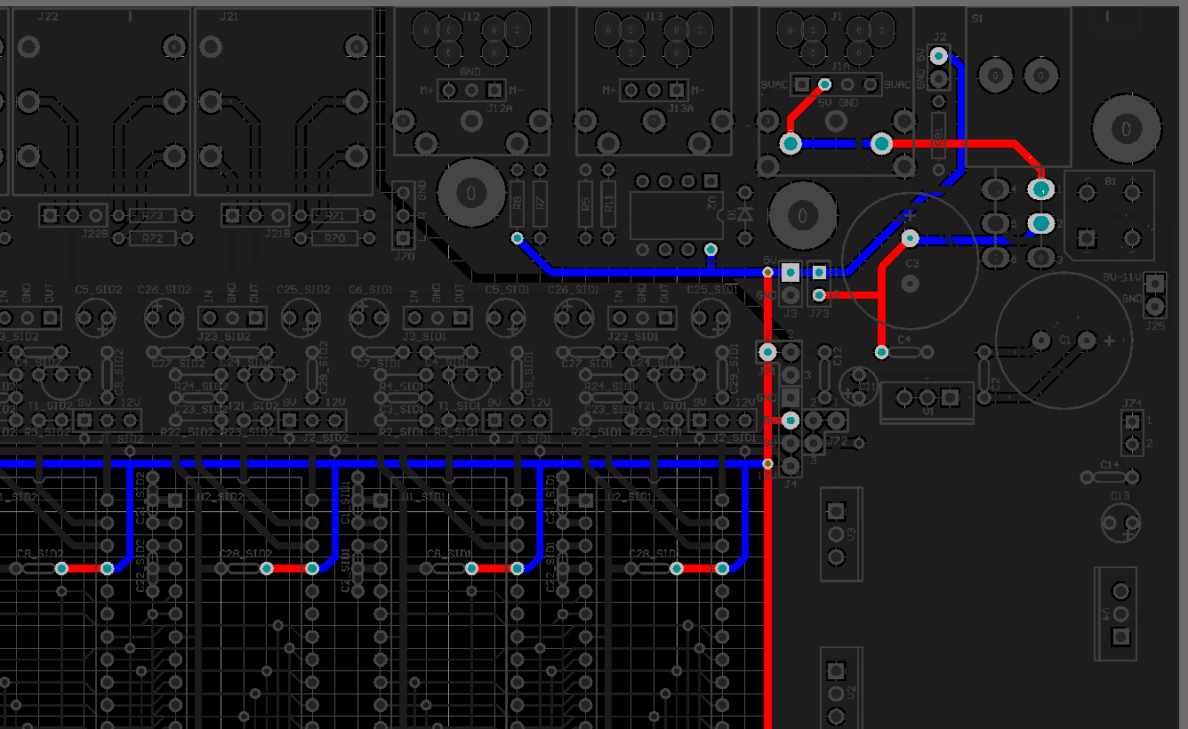
You've cut only the 5V tracks... all the pins that should be connected to ground still are connected.
So when you test pin 14 of the SID socket (ground) to 5V pins at J3, it's showing as connected. That's OK.
You can now test between any of the pins connected to 5V (like the picture of the 5V tracks) and any one of the ground pins (i.e. at J3 or J4).
You'll then notice that there is no connection in the SID sockets, and hopefully nowhere else lower than your cut track at point #1.
Perhaps you should now refer to the first picture I posted, showing the 5V tracks connected to the power socket and the switch.
Start desoldering the joints connected to these 5V tracks. You don't need to remove parts yet... just take off the solder. Just use desoldering wick/braid to remove the solder and check there are no shorts between the pad and the ground plane. Retest if 5V/ground are still connected after each joint is desoldered.
All the areas around the pads on the bottom of the PCB is connected to ground. Perhaps there is a fault in the PCB somewhere around those pads... a tiny bit of copper connecting the pad to the ground plane. Use a magnifying glass to see if there is anything there.
-
I can't find Edit or CC buttons described explicitly in the V2 manual.
They were in the original V1 specs:
http://ucapps.de/midibox_sid_csB.html
and then "reused" for Up/Down buttons for original V1 hardware.
Since I added dedicated Up/Down buttons to MB-6582, CC and Edit buttons now do what are referred to in the "Special Button Combinations" section of the User Manual:
http://ucapps.de/midibox_sid_manual_fp.html
- SHIFT + UP: CC mode on/off. In CC mode, a "knob" (rotary encoders within the OSC->Knob layer, or analog pots/joysticks) sends out value changes via MIDI Out, e.g. to your sequencer. The values can be recorded for MIDI automation.
- SHIFT + DOWN: EDIT mode on/off. In this mode, all parameter changes will be saved automatically into the currently selected patch whenever you change to a new patch. The LED flashes slowly if there is something to save in order to warn you, that the old patch will be overwritten.
- SHIFT + UP: CC mode on/off. In CC mode, a "knob" (rotary encoders within the OSC->Knob layer, or analog pots/joysticks) sends out value changes via MIDI Out, e.g. to your sequencer. The values can be recorded for MIDI automation.
-
I think the SIDstick was already "teased" here before:
Maybe someone can wrap up that SIDcog core into a SID-pin-compatible package like SwinSID. Someone with more time than I have. :thumbsup:
-
Ja ja ja... I am getting something organized now. PCBs and parts kits will be made available.
Do not ask questions, just wait.
-
My guess it is a software issue and something TK could look at. If you wired your modular exactly like the diagrams (i.e. you haven't needed to change the setup_?.asm to suit your DIN/DOUT wiring) then perhaps other people can check using their own modular setups.
-
:frantics:
-
:rolleyes: :smile:


Sammichsid : Problems with FW / Banksticks, **FIXED**
in Testing/Troubleshooting
Posted
Excellent reporting, I wish everyone would describe their troubleshooting like that!
I can't be exactly sure, but it sounds like adding the SIDs causes the current draw to be too much for the supply, the 5V supply sags just enough to make the PIC->LCD comms fail on startup, but otherwise the PIC boots OK and the LEDs flash etc.
Try inserting just one SID, maybe you have enough supply for the one, and you can actually get control surface + SID working and prove that everything SHOULD work (i.e. the SID isn't strangely interfering with the rest of the circuit).
Try also REMOVING the shunt in JBL. This will turn off the LCD backlight completely, removing more current draw from the system.
I also suggest you check your plugpack rating... maybe you are using something insufficient.
i.e. is it 12V AC 500mA or 12V DC 500mA etc... quote all three values, the voltage, the type (AC/DC) and the max current.