

Wilba
-
Posts
3,310 -
Joined
-
Last visited
-
Days Won
2
Content Type
Profiles
Forums
Blogs
Gallery
Posts posted by Wilba
-
-
Pulling out R12 was something to possibly fix a problem with the Optrex STEP LCDs (from fussylizard's bulk order). I don't think it has any effect for the fairly standard yellow-green LCDs that nebula was selling. I don't understand how removing R12 would affect LCD contrast, it's only a pullup on one of the signal lines to the LCD.
These displays work fine with ultracore, but they're not exactly 1:1, because it's only 14 pins on the header, and the backlight pins are on the other side. So only the bottom 14 pins are 1:1, the B+/B- need to be connected to the backlight pins on the other end of the LCD. On my setup, I have two wires of the ribbon cable extend past the 16pin IDC connector (attached to the LCD) and those wires soldered directly to the backlight pins.
Perhaps you're connecting the LCD to the 2nd LCD header on the ultracore, which won't show anything unless it's running an app that uses a 2nd LCD, like MB-SEQ.
JP1 configures the pcb to be used as a seq or a router. for seq, connect the left and center pins. for a router, connect the right and center pins.I think you'd want to configure it to NOT be a router.
-
I notice the ENC28J60 (for MBHP_ETH) isn't too widely available (i.e. not at all in my Australasia).
Bulk order? Or just add it to my next Mouser/Digikey order?
Any Aussies (and Kiwis) needing an ENC28J60 source can piggyback onto my next Mouser/Digikey order.
Maybe I should just get all the parts for the MBHP_ETH module in bulk... some of the other parts would be hard to find here.
Does anyone already have a BOM for Mouser?
-
J8_CORE1/J9_CORE1 in the Core section of MB-6582 base PCB is identical pinout to the J8/J9 header on a Core module. However, it is poorly labelled. Vss is at the end on the right. You will need to remove at least the first 74HC165 and 74HC595 in the DIN/DOUT chain on the MB-6582 base PCB (i.e. U16 and U21) so that there's no conflict with the external DIN/DOUT modules. You will also need to upload something like setup_8580.hex which uses the default DIN/DOUT wiring, as setup_mb6582.hex uses a different DIN/DOUT wiring (i.e. the combined LED/switch matrix).
(Sorry that I haven't been following this issue and helping you, I'll jump in after your next report).
-
I will buy the blue knobs if no one wants to buy the lot including the blue knobs.
Maybe a buyer would prefer the lot including the red or grey knobs.
(I was nicestupid and sold all my spare blue knobs to people over the years since I built the MB-6582 prototype.)
BTW to potential buyers, I confirm these are genuine new-old-stock 6582A SIDs from me.
-
1) It could be dead. Some people have successfully salvaged a 6581 from a C64. I am not one of them.
Can you observe a spike in the audio output when you turn on the C64? i.e. level meter jumps up to max then returns to nothing?
Also, do you hear anything on the audio, like noise, to suggest it's outputting something (i.e. prove your audio input is really working)?
2) C64s that need 12V (for 6581 SIDs) generate 12V internally. AFAIK they add 5V DC to 9V DC and then regulate this 14V through a 12V regulator.
3) It's hard to say what might have killed the 6581 in the C64, if it is dead. You could test the voltages on the SID socket, with or without the SID in it, to check it's getting 12V DC on pin 28, etc.
Don't use pliers to remove an IC. The cheapest extraction tool is better than that.

http://www.altronics.com.au/index.asp?area=item&id=T2550
I can't really recommend what's best... it's probably unlikely that the C64 will "kill" your other 6581s if you try them, but then again, I also read somewhere that connecting C64s to an amp can sometimes kill the SID, which is why the MIDIbox SID module has an audio buffer to "protect" the SID.
-
I don't know what you mean by "not backlight".
Maybe this is what you are looking for: http://character-lcd-lcds.shopeio.com/inventory/details.asp?id=935&cat=Lcds&sub=Character%20Lcd
Otherwise, browse here: http://www.crystalfontz.com/
-
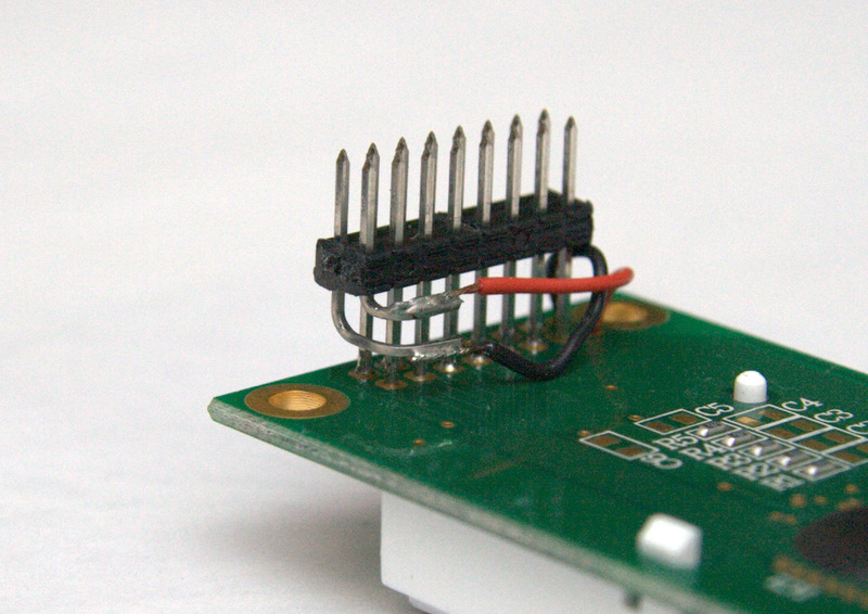
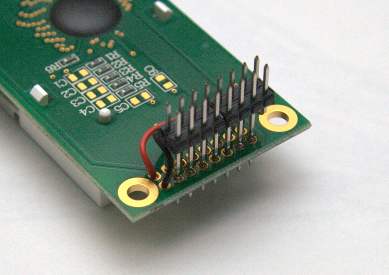
How to connect an Optrex STEP LCD to a sammichSID base PCB
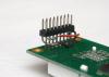
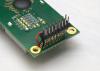
... and just to confirm: pins 3-16 on the display match up with pins 1-14 on the base PCB. Pins 1 and 2 on the display (backlight pins) match up with pins 15 and 16 (B+ and B-) on the base PCB.
I'll add this to the build guide someday :wink:
-
The good thing about these Displaytech LCDs is that it uses a single 3mm LED. If it ever dies, you can remove the bezel, cut the LED leads and desolder the remainder of them in the pads, twist the LED to break the glue holding it into the clear acrylic diffuser, then replace with another 3mm white LED. Replacing the bezel can be tricky, you need to get correct alignment between the LCD and the PCB via some conductive rubber things. If it's wrong, you get garbage on the display.
I just thought I'd mention it for future reference... some people would just replace the whole LCD, but personally I like to fix things when it's possible.
-
Daß ist eine gute Nachricht.
Viel Spaß!
-
Same pinout? It's completely different! It's a single row of 16 pads at the top edge, instead of 2x8 on the left side.
The ultimate white/black LCDs are the Optrex STEP displays:
http://www.optrex.com/products/partdetail.asp?PartNumber=C-51505NFQJ-LW-ALN
http://www.optrex.com/products/partdetail.asp?PartNumber=C-51505NFJ-SLW-AIN
I have the white on black one. It will work, but the pinout is slightly different, the backlight pins are at the opposite end of the header, which means you need to cut a couple of pins on the header and connect them to the pads on the LCD with two wires. It's an easy job to do, if you're interested, I'll post instructions and a photo of how I did it.
You'll probably need a new male header for the LCD, I have plenty of spares.
-
It sounds like this display is like the ones I have, they only have a single LED on the side, and so they don't need the maximum current supplied by the standard MIDIbox Core backlight circuit (and thus also MB-6582 base PCB), which is around 280mA or more.
I recommend inserting an 82K resistor in series with R4 (the 1K) or replacing it with machine pins (like you probably used for the SID filter capacitors as recommended by the build guide) so you can try different values. This will reduce the maximum current supplied to the LCD backlight. I'm surprised the LED hasn't burned out already.
Perhaps I'm totally wrong. What colour is this display? Does it look like it is uniformly illuminated or is it brighter on one side? If it's a negative white display (or anything other than yellow-green), it's probably edge-lit (single LED). The typical current (25mA) suggests only a single LED.
This doesn't quite explain the flickering though... if it was a current supply issue, i.e. too much current draw by SIDs + LCD, then it would stop flickering when there was only one SID.
What's the J3 measurement with only one SID? 4.5V DC is too low, it should be much closer to 5V (like 4.9V or more), so there might be a current supply issue at play here too, so you can confirm that by measuring J3 voltage with different loads, like one to eight SIDs installed.
It can't hurt to try replacing T1 and checking the solder joints in that area, in case a poor solder joint causes this intermittent flicker... but also, if it's only happening on power on and not later, that's suggesting the load is too much on power on and 5V supply is unstable but then becomes stable later. So you'll have to consider both possibilities (bad solder joints/T1 vs. current supply).
-
Good to hear it works now, but I don't understand what you mean... can you draw it on the image I uploaded in the previous post?
-
POIDH!
Good to hear it all works now. :D
-
IC2 is the optocoupler, it's only used for MIDI In. The two wires of a MIDI cable are "looped back" via a LED inside the optocoupler, so it is electrically isolated from the device. The phototransistor inside the optocoupler is what generates the signals to the PIC. It should have no effect on MIDI Out (i.e. if you remove IC2, MIDI Out should still work).
The LCD datasheet suggests you could run the backlight directly with a 5V supply, it has its own current limiting resistors, however, an additional 128mA on the 5V supply might make the 7805 run too hot. So in this context, you could probably run it with JBL=5V and JR4=closed (i.e. normal MIDIbox Core backlight circuit for high-power LCDs, supplied with 5V).... turn the brightness pot down as much as possible to keep current low (avoid heat in heatsinks). The resistors on the LCD should keep the current under 128mA if the supply is 5V (JBL=5V).
FWIW you can test actual current draw of the LCD by connecting your multimeter to read current (amps) passing through the two pins of JBL - instead of a shunt in JBL, you connect the multimeter to JBL instead, so the current goes through the multimeter. That way, you could try the "high power LCD" jumper settings and tweak the brightness pot to get the exact current you want (i.e. <128mA)
-
Are you measuring this "no resistance" with the IC installed?
If yes, take out IC3 and try again.
See if there are any shorts between adjacent pins of IC3 socket (and pin 7, 9, 14, I don't know why you checked these before but keep checking things again to find anything that isn't right).
Try also manually lighting the LEDs via the pins of IC3 and IC4 sockets (remove the ICs).
You can connect one of pins 2,3,4,5,6,7 of IC3 to ground, then connect one of pins 15,1,2,3,4,5,6,7 to 5V.
This should power one LED of the matrix.
You can take 5V from pin 16 and ground from pin 8 of either IC3 or IC4 sockets.
Do not put too thick a wire into the IC socket pins or they will become looser and won't make good contact with IC pins afterwards. Something like a cut resistor lead is OK, or the solid core wires used in prototyping "breadboards".
-
Reinstalling IC2 might have fixed something, if the contacts were not good before.
Can you show me a link to the LCD datasheet?
AFAIK there is no requirement for LCD "LED array" backlights to have a specific voltage, like 5V, maybe this is a minimum voltage because of forward voltage drop of two LEDs in series. If it says max current of 128mA (a strange value, actually) then you should configure the base PCB headers JBL and JR4 for "high-power LCD backlight" and set brightness pot less than half-way (probably 1/3 is best).
-
-
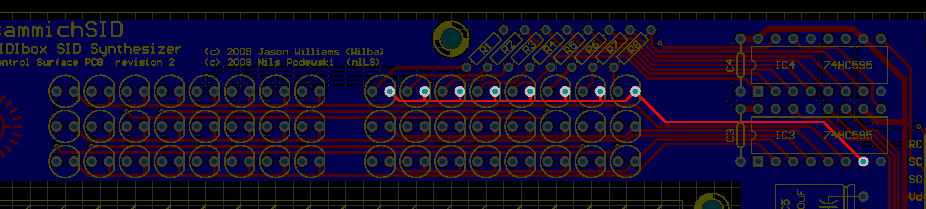
Maybe this picture can help.
You can see where the LED cathodes for the top right row are connected to the 74HC595.
It's possible the solder joint there is bad, or there's a short somewhere to another pin. Test connectivity between the LED leads and the pin of the IC from the top (don't assume the IC socket pin and the IC pin must be connected).

-
Let's assume that since you did upload successfully, the sammichSID MIDI Out should be working and unlikely to have suddenly stopped. Therefore it's probably a setup issue. You should be able to do a loopback (PC MIDI In connected to PC MIDI Out), play some notes on the keyboard and see events in the MIDI In window.
-
Ho ho ho. Ya koo tocha ka poonoo nee sok nyee.
-
The white/blue LCDs just have one LED on the right side.
I got a bunch of these LCDs cheap, but the LEDs were green. Don't ask me why they made such a yucky combo. Anyway, I just bought some white LEDs, took out the green LED and put in a white one.
So what you can do is, test if the LED is working by itself, and also test if there is power going to the backlight pins of the LCD header (on the base).
Testing LED is easy... just use a 5V supply through a resistor, anything between 100 ohm and 1K will be OK for this test. Disconnect the LCD from the base PCB (it can stay screwed into the CS PCB). Touch the wires onto the pins of the LED, where they are soldered to the LCD. You can also check it at the top two pins of the header, these pins would connect into the B+ and B- pins of the J16 header on the base PCB.
You can test if the backlight pins on the base is working too. Make sure you have JBL set to 5V, and JR4 doesn't have a shunt. Stick a LED into the B+ and B- pins of the header. A spare LED that came with the kit is fine. Cathode (short lead) goes to B- pin.
Most likely you have a bad solder joint somewhere, as I test each LCD before packing... but in the worst case scenario that the LED isn't working, I can send you a new white LED, it's pretty easy to replace... this is the main reason I chose to "recycle" these LCDs because they have easily fixable backlight LEDs and the replacement LED is a common 3mm LED.
-
sammichSID is an implementation of MIDIbox SID V2 Synth, which uses two SIDs in a stereo pair.
Go to www.ucapps.de and click on the links in the left navigation bar under MIDIbox SID V2 Synth
Such as:
http://www.ucapps.de/midibox_sid.html
http://www.ucapps.de/midibox_sid_manual.html
MIDIbox SID V2 Synth works like a SidStation - it's a MIDI controlled synth, with internally stored patches, loads of parameters for tweaking, etc. No disrespect towards SidStation, but MIDIbox SID has a lot more features in it's synth engine, and two SIDs sounds fatter in lead patches (Lead engine) and can be used for polyphonic patches (Multi engine) or two simultaneous bassline sequences (Bassline engine).
-
Are you receiving the upload request in the MIDI In window?
-
MIOS Studio only uses MIDI ports.
TM-1 should work, but not in any turbo mode, only standard MIDI baud rate.
grounding question r/ tactile switches and LEDs
in MIDIbox HUIs
Posted
You can tie all the LEDs and switches to a common ground plane. You don't need heavy-gauge wire between the boards, one wire of a ribbon cable is enough.
Since 16 (or 8) matches the number of inputs/outputs of DIN/DOUT modules, you might want to consider putting the shift registers on the same board as the switches/LEDs... then you'll only need 6 wires to connect these boards to a Core (or together)... otherwise you'll need to connect 32 wires (+ground) between these PCBs and DIN/DOUT modules. It's not much extra routing. This only works if you have enough room for the ICs, resistors and resistor networks.