

freddy
-
Posts
160 -
Joined
-
Last visited
-
Days Won
2
Content Type
Profiles
Forums
Blogs
Gallery
Posts posted by freddy
-
-
Hi Freddy,
I can wait .....
Orange,
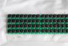
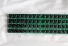
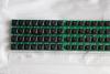
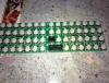
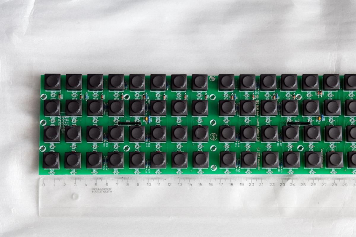
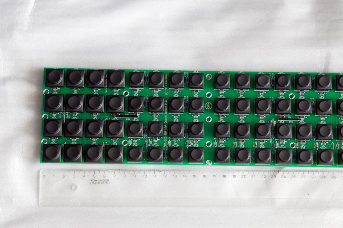
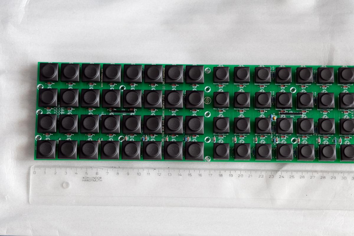
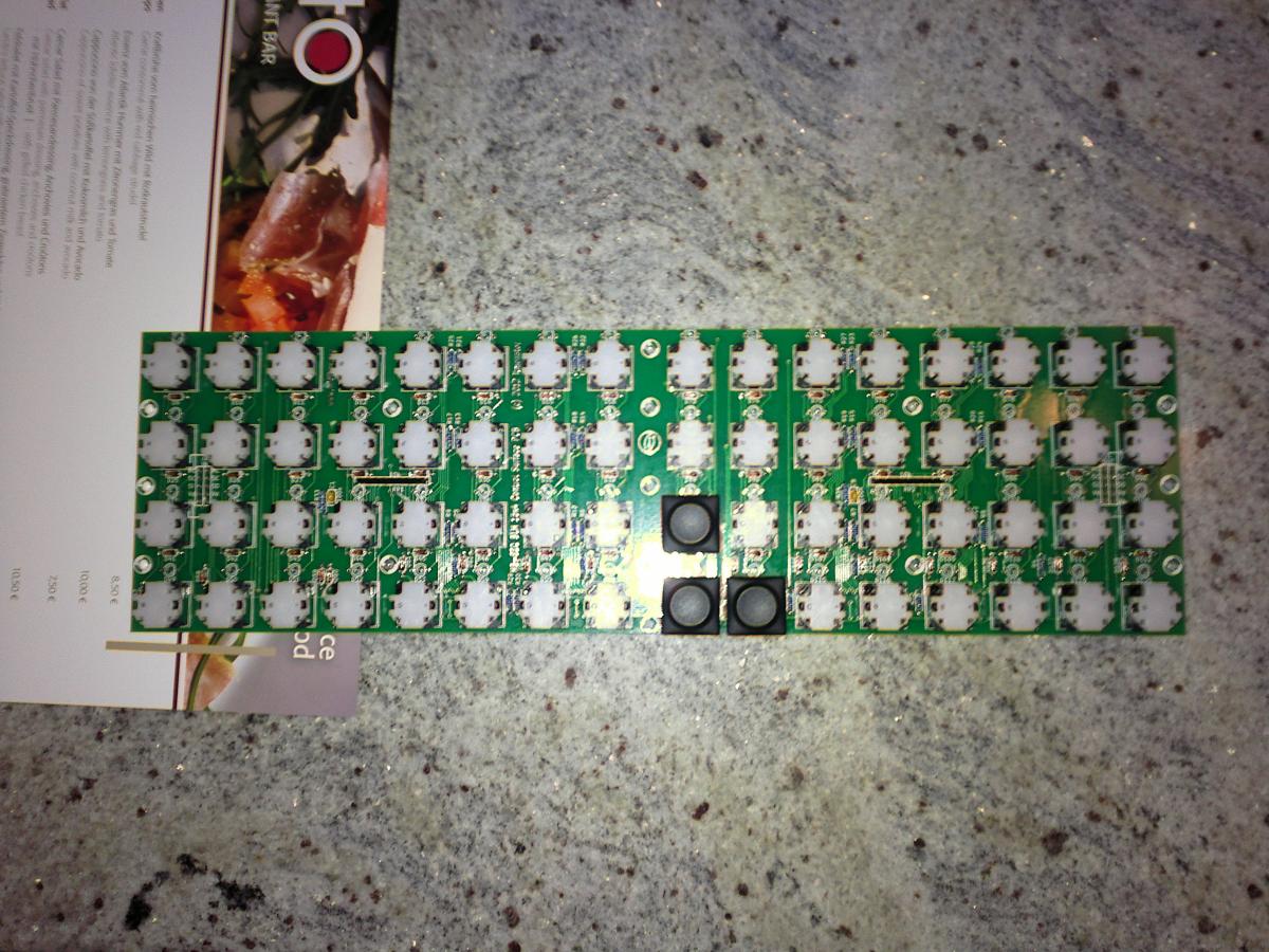
Here it is, the images are self-explaining, if you want to take picture from another side, angle, or caps combination, let me know, I'll have the camera around me till Sunday, flying back to Frankfurt on Monday.
Edit: I just realized that the 19mm caps will be covering the LEDs so the LEDs would need to bended a bit (by app 1.5mm) to the top. There is still enough place to fit a 3mm LED between the rows, though.
-
Without the proprietary Ploytec firmware these chips are obviously dumb. They can only be obtained from Ploytec, and in large quantities. If there is enough demand, TK might consider a new bulk order some time in the future. If I remember correctly, we are talking minimum quantities of 250 pieces here.
I'm not sure how this is done from the legal point of view but I just wonder if these chips could be offered at SmashTV's? I'm pretty sure he has more resources to get the chips in larg(er) quantities and have them lying around for some time. Definitely more reasonable than trying to get 250 orders in a bulk to get a tube :sad:
Just my two cents, maybe this was already discussed before (and was decided to be a no-go)...
-
Freddy: Wait until the design is finished before you order your parts. Otherwise you have to sell your unwanted parts again :smile:
point taken, though I wouldn't consider them being 'unwanted parts', 'extra parts' sounds better to me (though not probably to my wife when she walks by my DIYers lair) :phone:
-
ilmenator - no kidding, I told you about the source and the price before (PM on 7/1) though without the links :sad:
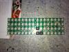
orange - while browsing PMs with ilmenator I found some poor quality pics of the 19mm caps, attaching them as a teaser before I'll make proper pictures the following weekend. Basically, to get an idea, using 16mm caps (the smaller and more expensive at Conrad) this leaves ~4,5mm space between the buttons as can be seen on ilmenator's Wiki page, using 19mm this leaves ~1.5mm for the panel width.
-
-
Freddy, you can offer me what you've got, but I have to check out the pictures beforehand. I am aiming towards perfection, so if that combination is cheaper but looking ugly, then I am out :shifty:, otherwise I am in :rolleyes:
Sure thing, unfortunately, I won't be able to post pics before following weekend (23-24/2). If you're unpatient (like I was) you better get the 16mm buttons till then, these were documented already on ilmenator's wiki :rolleyes:
-
Hi Guys,
I just figured that in the BOM there is no supplier mentioned for the switch caps. I found the following and I wonder which ones are the right ones ?
Snap In:
Plain:
I am just wondering if both will work and which of those are recommended ...
Thanks !
orange
Orange,
this one is 19mm (18.3x18.3 but 19mm hole), this gives the panel lines between the caps a bit too thin. I accidentally bought 130 of these (from another supplier) and could take a picture of populated board with the buttons over the next weekend when's my next home visit scheduled if it matters for you (still, they're 18 cents cheaper, for 64 this makes >10 EUR difference).
Anyway, I can sell you these if you want to, my local supplier has them here for 0,2910 EUR pp (excl 19% VAT). I could also sell you 64 buttons I've got spare, I got them for here for 0,62 EUR pp (again, excl. VAT, Conrad sells them for 1,40 EUR) - I bought two sets of buttons and (wrong) caps hoping for 2 PCBs from ilmenator :rolleyes:
Sorry for advertising, this should probably be part of Fleamarket topic.
Cheers,
freddy
-
LOL, quite a few interesting (and helpful) tips appeared here, I definitely will make use of them :rolleyes:
-
Daniel,
I made the fatal mistake with ordering only the caps hoping they'll fit to ordinary (i.e. Europe) 12mm tact switches but this wasn't the case. I had the chance do use my Dremel to cut approx 0.2mm from each switch which wasn't the way to go for me since the switches were alrady soldered in. This left me with two sets of DigiKey caps I'll sell you happily. But, actually, this makes the goods price vs. shipping ratio even worse for you since unless anyone else has spare switches you need to source them from DigiKey/Mouser anyway. Let me know if you're interested.
For my SEQv4 I ended up using different caps (round ones) and ordinary 12mm switches I was able to source locally and modified the panel design.
Hope this helps,
freddy
-
No problem with the display itself, it's HD44780 compliant, but like Duggle stated you plan to use multiple of these the wiring might be a pain...
-
we don't sell low amounts of chips at this point.
Pricing is EUR 3.50 @ 250 (tray) and EUR 2.50 @ 1000 (reel).
Well, I'd guess GM5 is a long run order, more a Fleamarket subject that the actual bulk order and getting even to 250 in bulk order will take looong time. This is even worse with last few GM5 boards being available from nILS, if there were more the chances would increase rapidly. Please don't read this as I'm ready to spend 875 EUR for the chips hoping for selling it but if we also got support from having the boards available I'd probably consider...
-
Looking at the datasheet i did not see any mentioning of a negative voltage.
Well, pins 15 and 16 are not connected based on the attached datasheet (though A+ and K- is depicted in the block diagram), maybe the pins are located elsewhere (I don't see them on the diagrams, though they could be located on the other side of the LCD for other MC4002D-series display I found datasheets for). This could be the case if swapping the two pins doesn't make the LCD light assuming the trimpot was turned there and back to make sure.
Hth,
freddy
-
@latigid on: if it would be possible to create -12v from +5v with your suggested solution, you still would need to power additional modules that you need the CV signals for. If those are in another box with a separate PSU it might work, I'm no expert. At least I would rather buy a known good psu than tinker with something else, I've had too many PSU related issues that put me off completely for a good while.
I'm about to use Recom RS-0512D in another project (being able to convert 5V to +/-12V), also, it's being used in mistralXG design (and I assume successfully) that was discussed some time ago. Maybe definitely worth a try but it's only up to 3W, which still should be plenty for few opamps.
Hope this helps,
freddy
-
Can you drill and engrave aluminium panels with this?
...and/or acrylic LCD windows - though I'm owning a CNC myself I never was able to get good results while cutting acrylics though this was probably a result of using no fancy (i.e. expensive) cutting bits. I used Cut2D program to create the tool path for Mach3, in case you're interested in giving it a try...
-
For those of you that came too late to get one of my prototype PCBs (or who just discover this thread now), I have documented the board design and everything you need to know to build your own unit over in the Wiki. You'll find schematics and Gerbers there (so you can order your own boards anywhere you like), as well as the BOM and some other hints.
Kind regards, ilmenator
ilmenator,
I've converted your AI back to FPD, I'm attaching it if you want to put it to the wiki. It was seated to 3U panel but the whole 16x4 BLM is a single block and can safely be moved around or copied/paste to another panel design.
freddy
-
The order placed was for 3 prototypes only and comparatively expensive looking back at the 16x4 BLM PCB. However, there are some tracks on this board that are running between the smd pads for the shift registers - I did not want to take any risk with respect to board quality.
Let's discuss larger quantities once the design has been confirmed to work :smile:. At least the size of this one is much more shipping friendly than the 16x4 BLM board.
Ilmenator,
understood and, of course, agreed. Looking forward for the bulk (if it happens), I'll wait with ordering the front panel - it fits so nicely next to your 16x4 BLM :-)
Cheers,
freddy
-
Board has been ordered, delivery in about 3-4 weeks to my place.
Looks nice, congratulations! Did you order 1-2 prototypes only for initial testing an then consider ordering larger amounts (if at all)? The obvious reason why I ask is that I'd love to test/usr one, too :-)
Cheers,
freddy
-
After a weekend of trace tetris I have a board design. It's a bit crowded there and not for the shy :pirate: . Harrrrr. Now I wonder if I need to test the official BPM display schematic like Hawkeye suggests or not? TK?
Looking forward to see the design finalized!
Your extension looks great. If you design your own PCB's for the extension I would be very interested in a set of them :-)So do I, though I probably will use some spare LCDs from my shelf-supplies so the pinout cannot be expected to fit, I hope I'll be able to solve it using wires.
What kind of buttons will you use for the 4 x 16 matrix ?Sorry for answering for ilmenator but since i have one of the boards as well these are Marquardt 6425 buttons (with no LED) with the 16mm cap.
-
Mine arrived as well, thanks a lot!
-
Hello,
if there are some spares (though I'm afraid i doubt it reading the thread through) count me in as well, I'm lacking a small portable FM synth, the whole MBFM just isn't really well-suited to travel with me by plane :rolleyes:
Thanks a lot,
freddy -
lucasmedus,
according to my understanding MF_NG contains a dedicated PIC, can be used standalone or integrated to some more sophisticated HUI and is accessed by MIDI, so there is no limit for chaining MF_NG units other that implied by MIDI protocol itself (within a reasonable practical limit, of course).
Correct me if I'm wrong, hope this helps,
freddy
-
Hi,
I'll take two cores, remaining DIN and two DOUTs. 2007 - which core PCB revision was that?
Cheers,
Adrien
-
I've calculated based on the http://www.ucapps.de...se_measures.pdf diagram, that H1 would be 44.10 mm. So would that mean that all we need is: H1= 49.1mm, H=86.82mm, T=125.20mm and B=434.50mm (17.5'' as in TK's design) or 482.6mm (19'')?
Hmm, the only problem is that Heidenreich page says H1 needs to be 45.0mm at least. Assuming TK's box H1 was 45mm I'd say 50mm would be a safe bet. I'm also not sure till where is H measured. Anyway, we're getting closer with the reverse-engineering :-)
One more remark - side panels are 3mm thick but with 1.5mm cutout. Since B includes the side panel thickness the 3mm (2* 1.5mm) should be added to front panel width to make B=437.5mm. And, that's 17.22", not 17.5", btw :-)
Is there no need to increase the T at all?There is no need to and you can't do that anyway because the panel will be too small after increasing T.
-
I am well aware off the fact that he is using STM32 Core. Not only because of the fact that he got the Core32 board frome me :wink:. If you look at the pictures, i never ever see more then a blank back panel. You can also notice that he is using low hex distance bolts as his board sits lower then the panel profile. So that would make the picture a good example for an LPC17 solution.
Ah, got it, I missed the point (as it usually happens with me, sorry about that) :sad:


MIDI Out to multiple MIDI Ins
in Design Concepts
Posted · Edited by freddy
Guys,
I can't seem to find (I always struggle with Google about using proper keywords) a way how to connect MIDI output (current loop, not TTL-level) to multiple inputs - MIDI standard permits that - without using additional hardware (that is without converting MIDI in to TTL and using the TTL level to drive multiple MIDI out circuits creathing a multi-Thru device). Should the connection be chained:
MIDI Out +    -----    ----------    ----------    ---- MIDI Out -
                  |    |        |    |        |    |
                IN1+  IN1-    IN2+  IN2-    IN3+  IN3-
or connected in parallel:
        OUT+  OUT-
          |     |
          +-------------+-------------
          |     |       |            |
          |     +-------|-----+------|-----
          |     |       |     |      |    |
        IN1+   IN1-   IN2+  IN2-   IN3+  IN3-
(Sorry about the ASCII, no mood to open Paint-like tool).
Thanks,
freddy