

freddy
-
Posts
160 -
Joined
-
Last visited
-
Days Won
2
Content Type
Profiles
Forums
Blogs
Gallery
Posts posted by freddy
-
-
Not going to build one of these, but can you provide a link to the LPC17 output buffers schematic please?
As smokestacksproductions suggested, it's referred from MBSEQv4 User Manual, "Hardware Options" chapter, "CV Outputs" section: http://www.ucapps.de/mbhp/mbhp_core_lpc17_output_buffers.pdf
6n136 is kinda weak, you want something that has more gain. 6n137 with a 10k pull up works for me, the 6N139 is the standard in the MHBP cores. You could also try a different brand 6N136 (this helped me with my 3030s which the same issue, I had a fairchild part in there and replacing it with a avago fixes it)
Okay, definitely will look around, replacing the input section won't be too hard, TTL pin has a separate connection connectable with veroboard-based replaced MIDI input circuitry. I'll look for another 6N136s first to ease my life.
The buffer circuit is to shift the level on the analog gates, it has nothing to do with the midi section unless you plan on adding midi ports 3 and 4
the 3.3v thing is not really the core problem, you would probably issues with other 5v devices as well that send out a bit of a rounded square that gets rounded off a bit more by the crappy opto to the point that the uC does recognize it as a valid msg
Ah, okay, thanks for explanation!
-
The problem is that the MBSEQv4 midi is working at 3.3v instead of 5v like MOST midi instruments require. You need to build a 5v level shifter. You can find schematic for this circuit on the MBSEQ hardware page it's called "LPC17 output buffers"
Very true, this was discussed quite recently ago. Thanks for the pointer, again!
-
Thx, you can regroup the 2 lines with my name in 1 line : 2 1 1 :flowers:
Sorry, missed it :-)
-
You realize that these two statements are contradicting each other, right?
Not really (unless I'm entirely missing the point in here), of course this was done as two separate steps:
1) watching OUT of MBSEQ showing the notes being played, to confirm the MBSEQ itself works as expected (no doubt, of course, but still strange),
2) connecting MBSEQ OUT to TR-9090 IN via an external interface in 'through' mode showing the TR-9090 input works after the signal is "amplified".
The 9090 is the problem here, follow the above advice and check the optocoupler!
Optocoupler used in TR-9090 is 6N136. That must be it, with non-amplified signal (straight from MBSEQ) I see no signs of life on optocoupler's pin 6 (optocoupler transistor's collector) - steady H there, with amplified one I can see H dropping to L. I have no logic analyzer to confirm the signal but since it works I guess it's just correct.
I'll consider either optocoupler and optocoupler circuit replacement, thanks a lot for advice(s)!
-
Folks,
while having fun with my shiny MBSEQv4 I'm able to drive MB6582 with no issues on both OUT1 and OUT2 but my TR-9090 clone doesn't seem to receive any messages. It seems to be MBSEQ issue because (I think) I've ruled everything else out:
- used different MIDI cables of course,
- using OUT1 or OUT2 makes no difference,
- connecting MIDI Monitor (in MIOS Studio) to MBSEQ output shows the notes and proper MIDI channel,
- connecting TR-9090 directly to MIDI Interface (not via MBSEQ) works as a charm,
- connecting MIDI Monitor (in MIOS Studio) to TR-9090's MIDI Thru doesn't show any messages flowing through TR-9090,
- connecting TR-9090 to the same output as MB6582 (and changing MIDI channel to 10) makes no difference,
- "amplifying" MIDI signal via an external MIDI interface (routing OUT to IN) does work as a charm again.
Could this be possible, in theory at least? Did anyone experience similar issue (maybe with an other equipment) as well? I'd suspect some part of my setup being faulty because I found other references to 808/909(0) in the SEQ forum but no clue what could it be...
Thanks,
freddy
-
Hummmm, add also for me 1 MB6582 and 1 MBFM, it will be usefull one day.... Diy is like that ! :ahappy:
Got you both:
		MBSEQ	MB6582	MBFM

freddy		4	1	2

rosch			1

NorthernLightX		2	1

jojjelito		1

Lamouette	2	1	1

monokinetic	2	1

dnode		2	1	1

gtxdude		2	2	1

kHz-tone		1	1

Arkay		2	1

Shuriken		1	1

Total		14	13	8
-
Thanks for massive interest! The current waiting list looks like this:
		MBSEQ	MB6582	MBFM

freddy		4	1	2

rosch			1

NorthernLightX		2	1

jojjelito		1

Lamouette	2

monokinetic	2	1

dnode		2	1	1

gtxdude		2	2	1

kHz-tone		1	1

Arkay		2	1

Total		14	11	6
(I hope I didn't introduce any copy/paste error)
This leaves 6x MBSEQ, 9x MB6582 (I took 20 instead of 10) and 4 MBFM windows available for rest of the MidiBOX nation :rolleyes:
I've placed the order online now, expected delivery date is Oct 19th to Oct 24th, so let's hope for the best!
Thanks again!
-
If you actually checked the fpd you would see the dimensions and corner radius is different. The next question probably is, why :wink:
The inner radius should be the same (1.5mm) on all designs, the window width is different, though (152.4mm on MBFM panel vs. 157.4mm on MBSEQ panel). Dunno why, either, though, maybe TK and Wilba used slightly different displays for each design? Maybe allowing wider looking angle for MBSEQ?
In TK's original design (can't find the link currently) the inner radius was different as well (1.5mm on the panel vs. 1.6mm on the window), not sure about the reason for that as well but in my files I made it the same (1.5mm).
I'm glad someone took a look at the files (and had no major design comments :rolleyes:). I'd guess I could actually place the order in two days...
Thanks,
Adrien
-
Guys,
as mentioned in another topic, I'll be ordering LCD windows for panelized MB gear from Schaeffer, namely MB6582, MBSEQv4 and MBFM. This is not a group buy (no time to maintain that, sorry), I'll be ordering fixed numbers of windows to get a better price for me and you (while keeping some for myself). Currently, the price breaks look like:
Gear\qty   1-4      5-9    10-19   20-30

MBSEQv4    14,91€  13,42€  11,93€  10,44€

MB6582     12,15€  10,94€  9,72€

MBFM       14,46€  13,01€  11,57€
(all prices w/o 19% VAT and shipping/handling fees)
I was thinking about ordering 20x MBSEQ windows (don't forget you need a pair for one MBSEQ), 10x MB6582 an 10x MBFM while keeping 4x MBSEQv4, 1x MB6582 and 2x MBFM for myself. According to another topic at least for MB6582 it seems no problem to reach 10 in total, I guess the same will be with MBSEQ builds (which seem to be quite popular build now since SmashTV offers the PCBs) and hoping the same for MBFM. Feel free to comment and indicate the quantities, maybe we'll get to a higher total (and a better price).
Again, this is not a group buy, just selling parts that will be left over. If you're interested, let me know, the prices are above, conditions follow.
The items will be located in Frankfurt, Germany, I'll be shipping world-wide (Europe-wide preferred) or offer a personal pick up, the price will be the actual shipping/handling (aliquot from Schaeffer to Frankfurt and from Frankfurt to you) plus the cost above based on the volumes I suggested. I'd prefer Paypal payment (or wire transfers to my country's bank, I'm just located in Germany and have no bank account there) or cash for personal pick-up but I'm opened to other ideas. I won't be making any money on this order so I hope no fancy requests will start to occur regarding services requested :-) I was intending using Deutsche Post as a carrier (but again, it's not carved in stone).
Please find the current design files attached in order to review and comment. The window designs are based on official panel design published on ucapps.de (for MBFM) and Wilba's Wiki (for MB6582 and MBSEQ) and follow the same rules as TK's window for MBSEQ (e.g. the cavity having 2,7mm left on each from the rectangular opening for gluing, the window itself has 0,4mm clearance from the panel opening on each side, the cavity is slightly bigger than the material used etc.), one of the main points of this topic is to validate the designs before ordering (makes sense, right?). If we manage to confirm the design and order this week I'd expect by the end of the following week (i.e. round Oct 19th) I could have received the windows and start re-posting.
I hope to hear from you soon :-)
Hope this works,
Adrien
-
It's about two things. Willing todo it and having a supplier. A year ago i tried to get something going for the MB6582 Window. But my supplier bailed on me. Which i cannot totally blame him for, it is as julian says, a lot of work which wont really make you much money.
Shuriken,
agreed, this thread was hi-jacked a bit. As mentioned earlier, I'll be ordering panels from FPE and will get myself bunch of windows as well (1x for MB6582 and 2 sets, i.e. 4 pieces for MBSEQv4). I'll open a new thread in fleamarket regarding this so I'd ask gtxdude, NorthernLightX, rosch, you and others interested to keep an eye (or two) on the new topic realy soon.
Adrien
-
gtxdude:        1

Arkay:          1

NorthernLightX: 2

Shuriken:       1

kristal=:       1

ytsestef:       1

----------------------

Total:          8
Shuriken,
count me in for +1 MBSID window as well, please (1.5mm panel, too). I'm also looking for MBSEQv4 2x40 window (x4) just like NorthernLightX (and I bet bunch of other guys as well, though MBFM uses 2mm panel instead of 3mm used by MBSEQ) but that looks to be different story. I'll be ordering from FPE pretty soon (definitely this week) so I could throw some windows as well if group buy won't work.
Thanks,
Adrien
-
D'akujem moc! Now it works like a charm. In my first try, I connected RC2 instead of RC1. And i had figured out the links between DO/DI & MISO & MOSI incorrectly. Thank you for helping me out! Have you posted on your projects? I'd love to see them.
And for all the other newbs around: the config in the post above is correct!
Martijn,
u bent van harte welkom! :rolleyes:
As for the projects, currently I'm finishing my first SEQv4, I intent do document the build of the second one considering the first one being a sort of prototype for me. Besides that it's MB6582, building an old SIDv1 (for 3 years now, case is usually the biggest issue for me) and bunch of assorted modules - some FMs, an ancient MIDIbox8 build back in 2001, a non-MB TR-9090 etc. Unfortunately, I'm more into electronics than into music but hopefully this will change with the new shiny SEQ :-)
Glad I could help, cheers,
Adrien
-
Thank you for your insights- i think i did it right, connecting a cable to the card is well documented and the different pin names are easily found on the web. i swapped miso and mosi but no result. I ll solder a female header to the cable and test the spare parts. One resistor looks out of place on this one. I ll let you know..
Martijn
here's an attempt of an ASCII art of the connections as well as the cable itself. Please note that as mentioned earlier I replaced the DIL by an (angled) SIL so the numbers are 1 to 8, not 1 to 16 (as it's on your's), consider these more a 'row number' than the actual pin number:
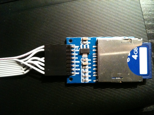
 LPC17 J16                     SD Card

 header                        SIL

 (top)                         (top)

  1  2     1  (Vss) - 1 (GND)    1

  ----     2  (Vss) - 8 (GND)    o-o- (GND)

 |o  o|    3  (Vdd) - 2 (3.3V)   o-o- (3.3V)

 |o  o|    4  (Vdd) - NC         o-o- (5V)

[ o  o|    5  (SI)  - 7 (MISO)   o-o- (CS)

 |o  o|    6  (SO)  - 5 (MOSI)   o-o- (MOSI)

 |o  o|    7  (SC)  - NC         o-o- (SCK)

  ----     8  (SC)  - 6 (SCK)    o-o- (MISO)

  9 10     9  (RC2) - NC         o-o- (GND)

           10 (RC1) - 4 (CS)     8
For clarification please take a look at the following (crappy iPhone) image of the SD adapter cable. The top-most cable (red-striped, actually) is pin 1 on J16.
As for the resistor(s) I guess that these act (in accordance with TK's note on the SDC schematics) as voltage dividers in case you're using 5V instead of 3.3V, so unless it causes short it shouldn't really matter. But that's just my guess, not confirmed and definitely not to be taken for granted.
Hope you get it working soon!
Adrien
-
Hello Adrien,
did yours work directly when connected? mine doesn't. I soldered DI -> MOSI; DO->MISO; RC1->CS ; SC->SCK; Vs->GND; Vd->+3V3. Does it also need +5V? I checked with the USB Mass Storage device (mios/apps/examples), but then the core does not see the SD card and the display sayd SD Card disconnected.
I have spare ones I will try, but Id like to hear your experiences. Thanks!
Martijn,
I built three cables (tested with 3 adapters) and all of them worked on first attempt. I'll post the cable pinout in few hours when I get back home (but I was following SD card schematic and made a little table for SD card vs. adapter DIL (that turned to be almost 1:1, in fact). The only thing that could have gone wrong is the MISO/MOSI cabling but you only have two choices here, the rest seems to be okay. I had both GNDs connected (as per SD card schematics) but internally they're connecter on the adapter PCB anyway, so this should make no difference, regardless.
No, I didn't connect +5V either, apparently there's a 3.3V regulator on the adapter itself to allow using it with 5V hosts - not the case for STM32 nor LPC17.
Be back in a few,
Adrien
-
To get back on topic: the card reader itself is ok, I have ordered one myself a few weeks ago. But mounting it in a case is a little difficult, as the two (only!) mounting holes are rather small and located very close to the DIL connector.
Also, the card reader is only soldered in the back. The front (the side on which the card is inserted) can be lifted up from the PCB, so a little soldering is required to fix this.
Just for the record, I bought a very similar item (http://www.ebay.com/itm/-/330658250543, in fact, it looks really the same) and only have two comments:
- the front side of the SD card socket is soldered to the PCB on the adapters I bought,
- there are in fact 4 mounting holes (seems to be 2.5mm diameter, however) but front ones are covered by the SD card socket itself, whence rendering these unusable for screws. Maybe the intention is not to use through-PCB screws but the front holes are more a notch for e.g. (threaded) shafts without actually going through the whole PCB. I don't know the correct English expression but I hope you know what I mean :rolleyes:
Anyway, I changed the DIL header for angled SIL to minimize the height (all pins are duplicated so no real need for DIL unless you are chaining the modules, and this can be worked around by a cable as well) and I am intending to secure the front side by inserting the SD card socket into the back panel itself while being hold using screws in the back.
Hope this helps,
Adrien
-
A snapshot of my workbench (reduced cable set!)

TK,
what's that box with lots of jacks and pots next to the scope?
Thanks,
freddy
-
TK has given us a few hints about it on the forums here and there, but nothing official just yet. It will be using the LPC CORE but will probably keep the PIC COREs for controlling the SIDs. The control surface won't change enough to make v2 control surface designs incompatible. That's about all I can remember :)
Quite enough (and all positive!) for the time being, looking forward for the official info!
-
That should be possible with MBSIDv3 but as it's not finished yet, one of these is probably what you want:
Wow, SIDv3 approaching? I'm impressed! Any sneak-peek preview available? :-)
-
I guess any future bulk order should be for a redesigned enclosure as the current design does not have enough space for the Core LPC17.
I'm waiting on TK's reply if he had made some pictures from the "not enough space" - in thread he mentions it could be fixed by "removing the top of the IDC connectors", not sure if he refers to the cable holders or the actual top (or middle, if you assemble the connector as expected), which wouldn't be that bad for me but I'd like to see that first.
I'm also waiting for the exact dimensions of the profiles and angles of TK's box to be able to calculate the new size. I'm willing to order some (10?) cases, keep 1-2 and re-sell the rest (shipping to EU preferred, it'll be a resale, not a bulk order).
Hope this helps.
freddy
-
I'm in contact with www.heidenreich.de for manufacturing nice looking aluminum desktop cases based on their
"Multiformis" system which can be used for 17"/3U frontpanels like Wilba's MBSEQ frontpanel, but also for other purposes/MIDIboxes.
Hi,
too bad I missed all the bulk orders :/ Slightly off-topic, but did anyone use Heidenreich's front plate service when the box was ordered? If so, any comparison to Schaeffer's service?
Thanks,
freddy
-
I already got an answer for that: The case we ordered is not big enough for the LPC17 board, so I ordered the Core 32 from SmashTV. :D
Forgot to post that here, sorry.
Ah, too bad for me, I got two LPC boards for experiments as well as for SEQ :-( Seems I have to look for another case, this one looks really good, though...
freddy
-
Does it make more sense to use the Core LPC17 or the old Core 32?
I only see a STM32 firmware so I guess it's better to use that one but I'm not sure.
Nope, you see 'MIOS32' firmware (though might be worth updating in the SEQ4 page to avoid confusion, it still says 'Precompiled firmware for STM32F103RE') :-) In the midibox_seq_v4_054.zip file both core type binaries as well as source files are available.
As for the core module itself, I remember TK saying 'use the STM32 if possible for old projects to help SmashTV's stocks disappear', not sure if it's still applicable though.
Hth,
freddy
-
you can check my blog on: http://www.bloggen.be/mb9090/
Ah, sorry, refreshing the blog regularly but I missed the last post from Nov 7th ;-)
I will start soldering the LPC board tomorrow with the parts that I got from Reichelt.
I soldered two during the last day, I had no issues, was finished in 2 hrs and it worked right after the power-of, I only had slight issues while getting familiar to LPCXpresso, but I succeeded there as well...
The 9090 is working fine!!! I love the drum machine. I only have to replace one potmeter because this is the one that is causing a hum from time to time.
Can't wait to have it finished :-) I started soldering diodes yesternight, can't really decide if I should solder by sections or by components size. If I get some silicone glue it'd be better to solder by sections but since I don't have the glue yet holding the small components while soldering them might prove a bit difficult, I'd say... Nevertheless, I'll figure it out somehow :-)
Good luck with the PCBs!
-
hey all,
Just wanted to share a 3d pic of my MB9090 SeqV4 (Roland 909 clone). :sorcerer:
And I would like to thank all of you that have already helped me: thanks :thumbsup: .
Hey, pcbatterij,
anything new on this topic? I'm just about to start soldering 9090 boards tonight and this one looks quite interesting. Any progress on the sequencer prototype built? :-)
Looking forward!
[S] MIDIBox gear LCD windows fromSchaeffer
in Fleamarket
Posted
You're there:
Looking forward to meet you! :rolleyes: