tomtiki
-
Posts
29 -
Joined
-
Last visited
Content Type
Profiles
Forums
Blogs
Gallery
Everything posted by tomtiki
-
I can solder SMT. If you need a tester or feedback, let me know :-) --tom
-
This is really nice. I would attach the front panel with standoffs, add a plain back panel and put rubber feet on the bottom. No case needed at all. If you decide to make a board, I would buy one. I built a MIDIBOX SID from a core module and 2 SID modules and my control surface has never worked right. I would prefer everything on a single PCB for reliability. As an alternative, if the control surface and SID/CORE/DIN were on separate boards, they could be stacked and it would be even smaller. This would also allow the control surface to be mounted separately from the other board and make a rack mount MIDIBOX SID very easy to build. Has anyone ever done a minimal control surface on a single PCB with controls and display mounted directly to the board? Like a sammichSID that would attach with ribbon cables to the CORE and DIN modules? --tom
-
Peter, I appreciate the answer. I'm going to investigate some different options. Of course, I have plenty of other projects to do. Thanks, Tom [
-
So, perhaps I should be asking : - Will this even work? (adding a keypad via a DIN module) - If it will work, would it be difficult for Midibox SID software to process patch/bank changes entered on the keypad? --tom
-
I have a Midibox SID with a basic control surface. Using the knob to select random patches is not the best when you are trying to pick a specific patch, or a higher numbered patch. In performance, there are generally lighting problems and these displays can be hard to read. Being able to enter a patch number via a keypad would be more efficient. A display would be nice, but not necessary. I may look at the C64 8x8 keyboard encoder to see if I can make that work. The software would then have to be changed to accept input from the keypad. There should be a way to do this as a Midibox module which could plug into the DIN/DOUT bus rather than MIDI. That would avoid the requirement for a MIDI merger. Update : Just found some 16 button keypads in my parts box. They are wired as individual switches with a common ground. Keys are 0-9, A, B, C, D, # and *. I could just connect this keypad to a DIN module, then I would just need software to make it work. Pointers on how to do this would be appreciated. --tom
-
A simple description of what I am looking for is a Midibox SID version of a Yamaha MU5 : http://usa.yamaha.com/products/music-production/tone-generators/mu5/?mode=model The built in music keyboard is not necessary, but would be nice. Patches can be changed from the built in keys. I would like to be able to type in a patch number directly rather than using a rotary encoder. I'm thinking a 4x4 matrix keyboard. My end use of this would be for my son's marching band to be able to integrate SID/chiptune type sounds into their performance. I realize that i could build a separate box that would send these bank/patch changes, but that would use the MIDI IN port...then I would need a merger. If this was doable through the CORE without going through MIDI, it would be much simpler. I found the project that allows a C64 keyboard into a Midibox project, but that would make the system too large and contain many unnecessary keys. Thoughts? Sorry if I am missing something obvious. --tom
-
According to the midibox sid CC implementation chart : http://svnmios.midibox.org/filedetails.php?repname=svn.mios&path=%2Ftrunk%2Fapps%2Fsynthesizers%2Fmidibox_sid_v2%2Fdoc%2Fmbsidv2_cc_chart.txt CC0 is bank change and CC32 is "Voice 123 Portamento rate" I obviously have something confused. If someone could point me at information on how to do patch and bank changes from a practical sense (on an actual MIDI controller keyboard), then I will go read that before asking any more dumb questions. Has anyone ever wired a numeric keypad directly into the Midibox SID so that patch and bank could be typed in directly? I have a Yamaha MU5 Tone module with a built in keyboard and display that does this. Here is a commercial product that sends patch change commands : http://www.musictechnologiesgroup.com/midipatch.htm If this functionality (bank/patch change via keypad) could be added to the Midibox SID, it would be pretty much what I am looking for. Thanks, Tom
-
Is there a way to send patch changes to a headless (no control surface) Midibox SID? I'm thinking of a performance situation where patches could be loaded in advance and I would just select them from my control keyboard. I suppose it would be the same situation with a rackmount Midibox SID. Sorry if this is an obvious question. I did not see this information in the docs. Thanks, Tom
-
Is there any US supplier of bankstick PCBs? I could order from mikes but shipping is kind of steep. My hand soldering skills are pretty terrible. If we can get a number of people that need them, I could make a bulk buy from Mikes to keep the shipping costs down. --tom
-
I would like to add a second SID to my MidiBox SID setup. I was reviewing the wiring diagram here : mbhp_8xsid_c64_psu_optimized.pdf What is the optimal way of connecting the two SID boards to the core with rbbon cable? I have looked through the forum and wiki and MidiBox documentation. Should I make a 10 pin ribbon cable with 3 connectors, then cut the wire to the SO connection on the second SID board and solder that to a wire that goes to J14 of the core? Is there a better way. FYI, I am currently using a straight 10 pin ribbon cable between the SID and CORE module. I am not feeding the power via separate connections as shown in the wiring diagram mentioned above. 5V is being passed through the ribbon cable, and 12V is connected via a separate wire. I am using a power supply removed from surplus equipment and have no noise issues. Thanks, Tom
-
I'm thinking of doing the same...just finished a MB SID with the minimum control surface and would like to add 5 more knobs by using the analog inputs. I looked at the MB64 documentation to see how to wire the pots and could not find a wiring diagram. Also did not see anything in the wiki. I also searched the forum and could not find anything. Thanks, Tom
-
Midibox SID V2 with simplified performance interface
tomtiki replied to tomtiki's topic in MIDIbox SID
I already have a built DinX4 module. The Step A surface only requires 2 of the DIN sections. Which other controls would be good to add, only using the remaining 2 sections of the DinX4 board? Some combination of buttons and encoders. Thanks, Tom -
I have a finished Midibox SID V2. I have not built a control surface yet. I would like a simplified, performance oriented interface that would allow me to plug in a MIDI keyboard, select one of the predefined patches, then use the MIDI keyboard to play the MidiBox SID. Will the "Step A" control surface allow me to do this with a minimum of fuss? Thanks, Tom
-
Why not use 2 wall warts of appropriate voltages (9VAC and 5VDC) and just wire them up? I personally don't trust the old C64 supplies. The SID chips are worth more than the risk of burning them up when the supply fails. --tom
-
Jim, So, pistons are used to save combinations of stop key settings. right? (If there is a primer of organ terminology, please point me at it...) I have another "parts" organ (Gulbransen Premiere) with 6 buttons between the manuals, but everything is electromechanical. I don't believe that these would be reusable. So, I program the pistons in the Miditizer software, then use the piston buttons to activate the specific combinations? For what its worth, I have the 2 keyboards for the Gulbransen, but the "combination action" mechanics attached to the back make them quite large. The Schoeber keyboards are relatively compact. Thanks, Tom Thanks, Tom
-
Jumping in here...I'm thinking about a digital organ console to drive something like jOrgan or Miditizer. I have two 61 note keyboards from a Schoeber organ, and stop tabs from an 80's Baldwin. Sounds like I should start with MidiIO128 to midify the keyboards, one keyswitch per input. That leaves me 6 leftover. Anything reasonable I can do with 6 inputs and my stop tabs as a first step? I also have a 13 note pedalboard with integrated switches from the Baldwin. I know that is a compromise, but I'd like to keep the physical size to a managable (portable?) level. --tom
-
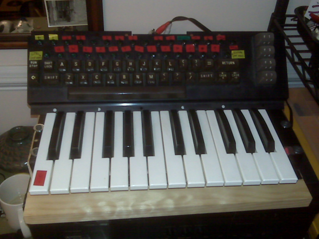
I've been reading the posts discussing the addition of a piano keyboard to a MB SID. Finding this link : <http://www.midibox.org/dokuwiki/doku.php?id=midiboxkb_-_using_a_c64_keyboard_as_input> was an interesting coincidence. I have been working on a C64 piano keyboard controller and chose to interface a piano type keyboard with a C-64 keyboard. The controller works with any C64 as the only interface is through the keyboard connector. Basically, I'm implementing the common C-64 plastic keyboard overlay as a full size, 2 octave keyboard (photo attached). This was designed as a controller for Paul Slocum's CynthCart : <http://www.qotile.net/cynthcart.html> I'm also starting on a MB-6582 project shortly, and am interested in merging the two. Presumably this would allow me to "play" the MB-6582 via the piano keyboard?....perhaps more code is required? --tom
-
So, if I used a 40x2 LCD (which I have), 5 of the buttons would have encoders underneath them, and the other 5 would just have buttons? I like the idea of dedicated buttons to select commonly used modes, and encoders specifically for certain parameters. In any case, I just ordered the MB-6582 PC board and additional parts. Planning the build in a C-64 case which should leave me plenty of control surface space along with the LCD. Already have a dedicated power supply that I "harvested" from a nicely built piece of obsolete equipment. Thanks again. I'll likely have more questions as the build proceeds. Cheers, Tom
-
Wilba, I don't necessarily need to use the sammichSID CS board. I was indeed thinking of using a 2x40 LCD, as I already have one. And some encoders. I guess I'm more interested in the details of the DIN/DOUT configuration for the sammichSID...how you implemented the used definable buttons, for example. Another option is to buy the MB-6582 CS board and only partially populate it. Sandwich the 2 boards like the sammichSID, then just run control wires for those switches and encoders that I want to use. I can see it being worth the $20 for improved reliability. I would probably also want the feedback pots on the front panel. I would put everything in an old C-64 case and integrate the power supply. A more general question of interest is : When using the full control surface, which controls get used the most? What is the optimum control surface complexity that lies between the sammichSID and the full blown CS-6582? I'm also interested in being able to use the MB-6582 as more of a standalone device...kind of a Midibox SID jam box. Don't get me wrong -- I'm very impressed by what you have done, but personally want something with a simpler interface. Thanks, Tom
-
I currently have an unfinished MB SID V1, and am planning to get the MB-6582 PC board as a way to upgrade from V1 to V2. This will allow me to easily expand to more SIDs with little additional cost. I can repurpose many of the parts I already have (display, encoders, etc), and very much like the idea of everything on a single board. I am NOT, however, very interested in building the full blown control surface. I really like the simplicity of the sammichSID interface. I presume that this interface could be easily implemented with the MB-6582 board. Put the head (CS) of the sammichSID on the body of a MB-6582. A frankenSID :-) I already have an encoder, a display, and buttons. And plenty of empty C-64 shells :-) Wilba....being the creator of both the MB-6582 and the sammichSID, you've probably thought about this. Could you provide enough information so that I could make this work? Thanks, Tom
-
I have some older versions of the SID and CORE cards and need some guidance on how I should proceed. I have been looking at various PDFs and web pages, but am still have some questions. I'm pretty sure I want to upgrade to SID V2. I'm coming back to this after a fairly long break. NOTE : after writing this (everything below), I found a link to this web page : http://www.ucapps.de/midibox_sid_manual_up.html which clears up some stuff, but I have other questions...continuing I bought the CORE and SID modules from Smash TV (a while ago). They are : - CORE R3 - SID R2 These have been built. I have modded/updated the boards as such : - CORE R3 - jumper from PIC pin 17 to CLK pin on J10 - SID R2 - Removed XTAL, jumper from SID CLK input to CLK pin on J2/CLK I've got the older PIC 18F452 chip with the 1.7 firmware. At this point, I'm thinking any further mods are only needed if I want to do the SID V2, which requires a processor upgrade. Any reason I shouldn't? I also have a DIN R2 which has not been built yet. From the notes on Smash TV's site, it looks like I just need to add bypass caps, but it looks like J4,J6,J8,J10 have been moved to the other side of the chips. Perhaps I should just get a new DIN PC board while I am ordering a new PIC? Here's where my confusion starts. This page on the SID module: http://www.ucapps.de/mbhp_sid_old.html Raises some questions : -The CLK pin once connected to the J10/CLK appears to now be routed back to the CORE via the middle pin on J7 (which is connected to the same pin on the PIC). Does this need to be changed? -How can I use a 1:1 connection from SID J2 --> CORE J10 with a wire (blue on the diagram) going from J2/SC to J10/MD? -The web page shows power for the SID coming from CORE/J2. This does not appear to correlate with the pictures lower on the web page showing a regular jumper cable going from SID J2 to Core J10 On the CORE, I think I just need to add the R12 pullup from J4/SC. Questions concerning power : I am building this into a chassis I salvaged that already has a +5v/+12v regulated power supply built in. It looks like I should remove the 7805 on CORE and replace it with a jumper between pins 1 and 3. OK so far? Then similarly replace the 7812 on SID with a jumper across pins 1 and 3. It looks like the 5V is being passed from CORE to SID via J2. Since my power supply is +5, +12 with a common ground, are there any other changes I should make? Do I need to remove the bridge rectifiers? Thanks for your help with this. --tom
-
Would like to swap a 6581 for an 8580. Preferably someone in the U.S. (cheaper postage). --Tom
-
Actually, it didn't take me long to find the pinouts. Guess I was just tired when I wrote that last post. As for the wiring, unfortunately, a straight through cable is impossible. So, I've got the J15 header on the core board and either a 14 or 16 pin IDC on the display. I could use an IDC on the J15 side, but then...major wire splicing : core lcd j15 display ----------------- 6 1 vss 8 2 vcc 10 3 vo 12 4 RS 14 5 R/W 16 6 E 15 7 DB0 13 8 DB1 11 9 DB2 9 10 DB3 7 11 DB4 5 12 DB5 3 13 DB6 1 14 DB7 ---------------------- 2 15 backlight + 4 16 backlight gnd For the 40x2, the backlight wiring would be different. So what is the best way to do the cable conversion? Cut the cables and splice all the ends? ....perhaps I could wire an interface cable to convert the J15 wiring to be compatible with the IDC socket on the display? I would have to make separate ones for 14 and 16 pin displays, but once the interface cable was plugged in, I now have somewhat standard wiring. Best way to do this? Any other ideas? I can start a list somewhere..... Thanks for your suggestions.. --tom