tomcody
-
Posts
65 -
Joined
-
Last visited
Content Type
Profiles
Forums
Blogs
Gallery
Everything posted by tomcody
-
I think I found the problem. I'm using a dvd player switching power supply and its +5 Volts varies between 5.25 and 5.4 Volts. I tried with 5.0 volts coming from an adjustable power supply and the LCD works fine, never got stuck. May be is the PIC or the LCD that have problems with voltages around to its limit (5.5 Volts). Well I hope my experience can help somebody.
-
Thank you for your reply. Yes I set the connectios like that but the problem persist. Then looking in the wiki I found this: ;; using the 4-bit interface: ;; -> connect MBHP_CORE:J15:D7-D4 of the core module to D7-D4 of the LCD ;; -> left MBHP_CORE:J15:D3-D0 of the core module open! ;; -> tie D3-D0 of the LCD to ground So I tried it (D3-D0 of the LCD to ground and D3-D0 of CORE open), but again the problem persist, I don't know what else to try.
-
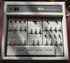
sorry too big photos: Thank you in advance for any comment.
-
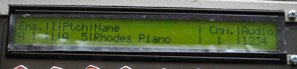
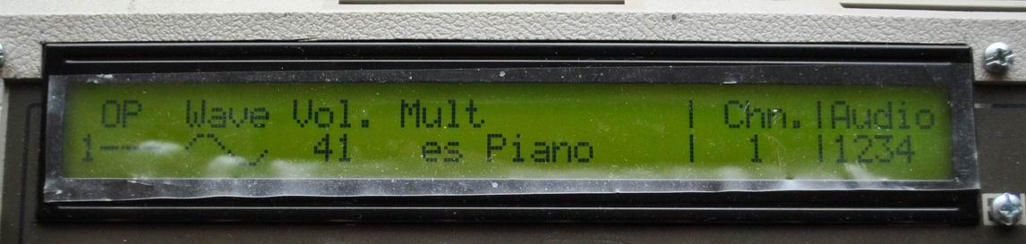
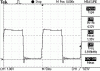
here some photos: as you can see just a part of the LCD get refreshed, then get stuck and I have to power off-on.
-
first I wired up the 8, then only 4 and D0-D3 from the LCD to ground and D0-03 from CORE open. The strange thing is it doesn't get stuck when I move the data dial, but when I use the selection matrix or the v-pots it gets stuck after 3 seconds ... I don't understand why, please any help? Thank you for your reply.
-
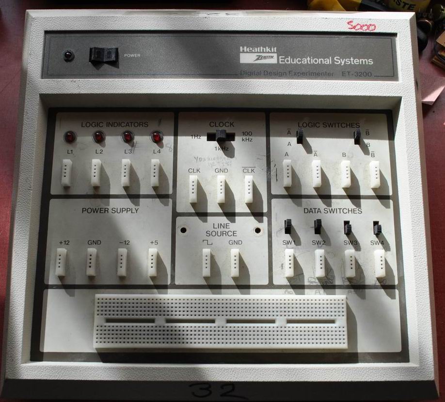
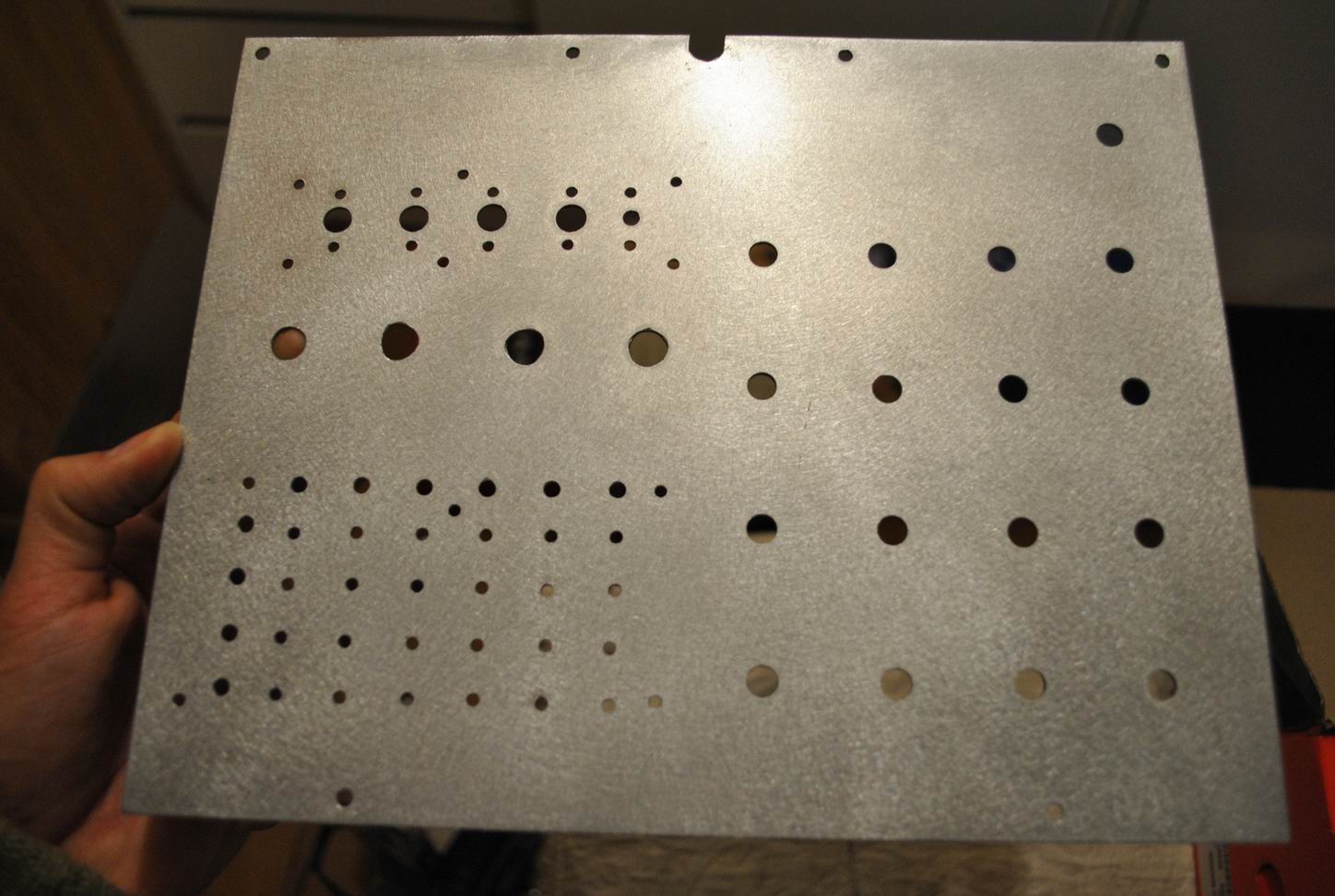
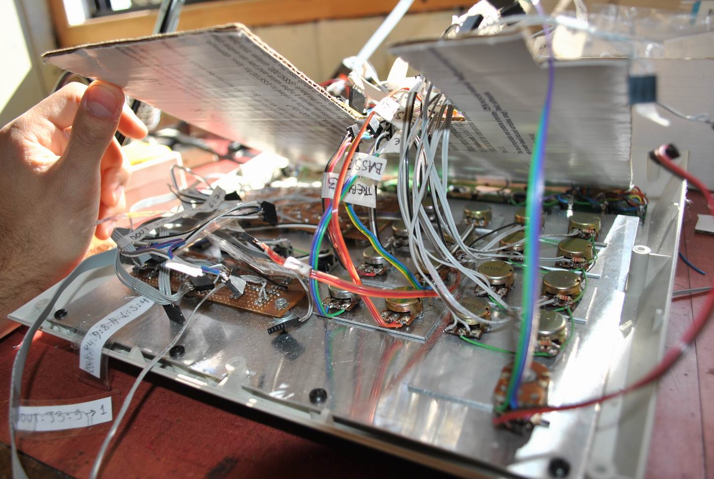
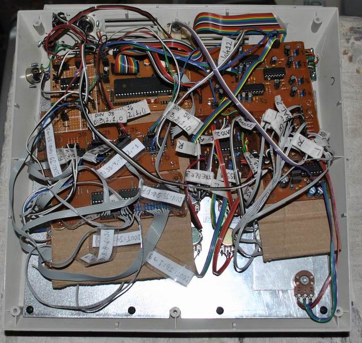
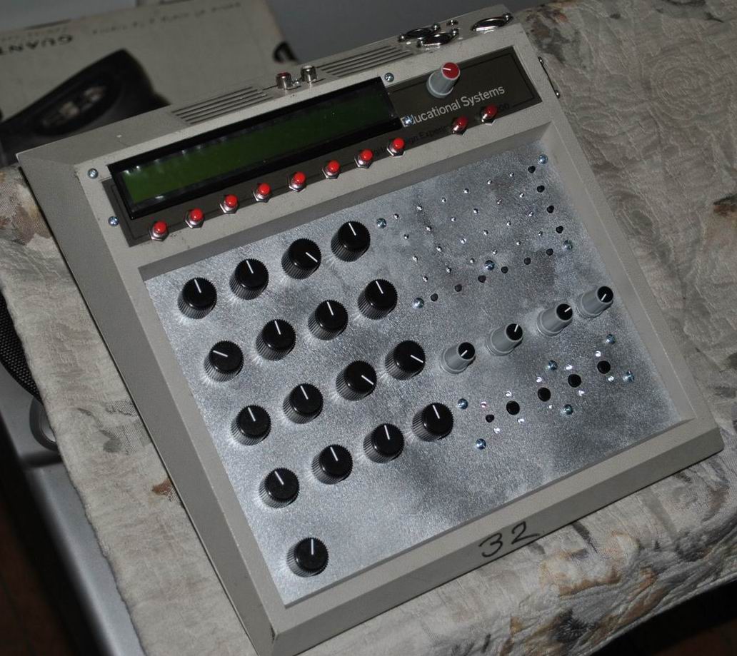
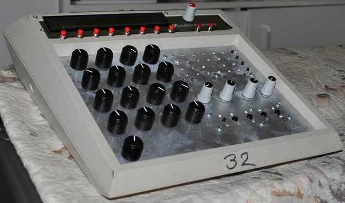
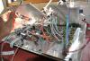
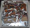
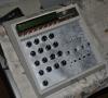
Hi everybody I finished my mbfm + built-in 4-channel stereo mixer + tone control. I built it around a heathkit ET-3200 case. The mixer has balance, volume, phone amp and RCA connectors. I used a dvd player power supply (+5/+12/-12) and works fine. Here some pictures. But I have a problem: with a 18F452 the LCD works fine, but when I use a 4685 it gets stuck after pressing/rotating a little bit here and there (but the rest still working, it plays notes and I can change parameters ...). I looked around and realize that 4865 works in 4-bit mode with the LCD, but still the problem after fixed that. I thought in a corrupted midi transfer but the 452 works fine. What can be the problem? Thank in advance for your comments.

-
Thanks for your reply Imp, fortunately I have a 18f452 and did the connection test with it and all OK ... :thumbsup:. Then I loaded setup_pic18f452_mbfm_tk.hex and the LCD showed me the mbfm menu ... :thumbsup:. Then I loaded the 1kHz test sound and it sounded in all the channels ... :thumbsup:. :laugh: :laugh: :laugh: :laugh: !!!! I don't understand why the LCD doesn't showed anything with the 18f4685 ... I used the latest .hex files: bootloader_v1_2b_pic18f4685.hex mios_v1_9g_pic18f4685.hex setup_pic18f4685_mbfm_tk.hex Maybe because of using the minimal requirements? Well I don't use ferric chloride, instead I use nitric acid and takes less than a minute and goes a long way ... in fact I have to water down a lot this thing or the PCB will end with no copper and all the toner floating in 3 seconds :rofl: Well I think for the momment is solve my problem but the 18f4685 thing. Thank you again for taking the time. Tom.
-
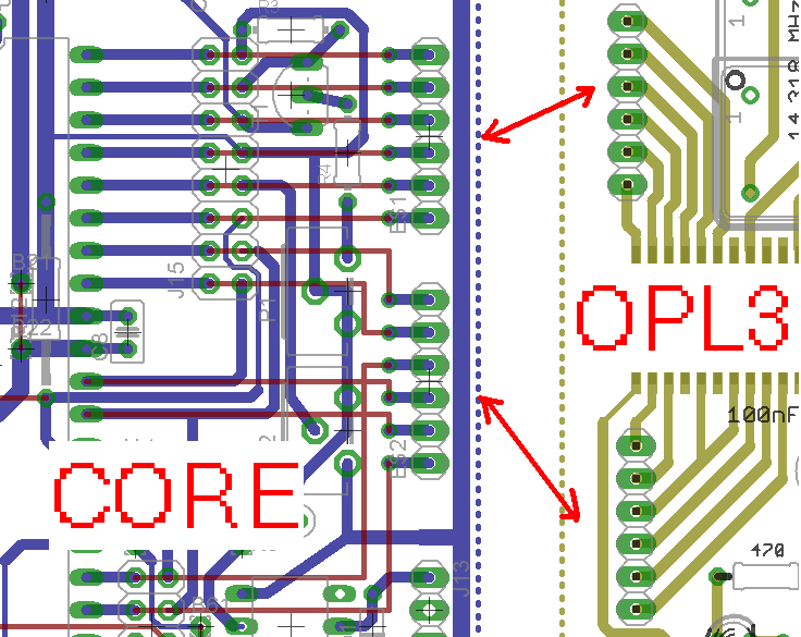
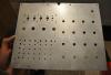
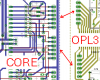
Hello, I'm making the MIDIBox FM and at this momment my system is like the minimal: CORE with PIC18f4685 + MBHP_OPL3 + LCD + bankstick. In this I posted that some pin of the YAC512 was unconnected to ground. Finally I finnished the MBHP_OPL3 without ground plane, so the ground of 5+ was unconnected to the ground of +12-12. When I tested the module for the first time the OPL3 chip got a little warm, I did the connection test (mbfm_interconnection_test_v2) and the D0, D1, D2 & D3 pins always reads 5V. The remaining pins works OK (the LCD worked OK too). After this I loaded setup_pic18f4685_mbfm_tk.hex with all my system interconnected hoping the LCD will shows me something but nothing happened (just the upper LCD line in black). Then I loaded the 1kHz triangle test and no sound :sad:. After 4 or 5 times the OPL3 chip doesn't got warm anymore :huh:. Then I realized that the oscillator's GND pin was connected to the +12-12's ground and not to the +5's ground so the oscillator never got power and the OPL3 chip never got the clock signal, now it's fixed. I did triple check both circuits. summarizing: CORE are working OK except D0, D1, D2 & D3 pins (I think). LCD working OK. MBHP_OPL3 PCB OK and all components correctly mounted, green led lighting. CORE & MBHP_OPL3 connection OK. Not soldered, but through ribbon cable connection (see pic). I'm afraid my attempt to save toner was the error (no ground plane). Could this damage the OPL3 chip :bye:?. Maybe the clock pin was floating because of that and that's why got warm I dunno... Thank you in advance for any reply.
-
I do understand it's upside down, in my case I have to connect the pin 2 to groud because I'm not making the PCB with ground plane (toner saving :wink:) and that's the only commponent (appears to be) is not physically connected to ground line. Thanks for your replies.
-
Hola MidiFos, recibà la confirmación el mismo dÃa que tú, se demoró un poco más de 3 semanas en llegar, tal vez serÃa útil preguntar en los correos de tu paÃs porque eso me han acosejado cuando hago compras por ebay cuando se demora mucho. Un saludo desde Chile y suerte en tus proyectos midi.
-
Hello everybody I realized that in the IC2 (upper YAC512) the VSS pin is not physically connected, however when using ratsnest appears connected. I'm not a specialist but how can IC2 work without a ground? Thank you in advance :smile:
-
Yesterday I've received my opl3 chipset thank you! :smile:
-
wow monokinetic! thanks that's a good page, I will try that circuit and follow the Janis1279's indications and post the result, if doesn't work I will follow the nILS's indications and hope for the good will of an midiboxer :D . Thank you everybody. TomCody
-
Hello everybody, I'm starting gathering the part to make an midibox fm and I realized the difference between a crystal and oscillator ... but too late :tongue: 'cuase I bought a bunch of crystal from ebay. I know there are a lot of webshops but the shipping to my country are very expensive compared to ebay. So I've found this page looking for a solution: http://www.gaby.de/z80/uexosc.htm I saw the scope pictures about the 74LS00 circuit and looks like a nice TTL pulse at the output :thumbsup: , so this may work, but the guy doesn't specify the max frec. this cicuit will work (the circuit uses a 4 MHz crystal), maybe a 74HC00, I don't know. The bad thing is if someone choose this solution needs to make a circuit apart for this or to know how to use the eagle to edit the schematic. Have anyone use something like this? What do you think? Thanks you. TomCody.
-
Hello, is this bulk order for 1xYMF262 and 1xYAC512 right?, so if I want 1xYMF262 and 2xYAC512 for 4 channels, Do I need to sign for 2 chipsets?. Thanks. Tomcody.
-
That worked out. I've looked the 24LC256 datasheet and says the operating range is: 2.5-5.5V. The reason why Vcc>4.5V is a clock speed issue? If so the 24C04 for the GM5 chip also need Vcc>4.5V? Thank you TK. TomCody.
-
Hi everybody, I need to feed the CORE with less than 5V, let's say 4.5V or even less (the microchip page says operating range is 2 to 5.5V). I did some tests with a adjustable power supply and a PIC with just the bootloader. When the voltaje gets lower than 4.60V (4.59V) the CORE stops sending the request message :shocked: , I looked the PIC18F452 datasheet and there are the Low Voltage Detect Control register, LVDCON thats defines a voltaje range in which PIC gets interrupted if some bit are set. I've done a fast look in the code but didn't find LVDCON. Do I have to do some modification to the code to get the PIC working with a voltage lower than 4.6V?. Thanks for any comment. :thumbsup: TomCody.
-
Received my parts today - the pcb is beautiful :D, thanks TK and good luck everybody soldering the chip ;)
-
En el post que puse en Design Concepts me avisaron que me equivoqué en el circuito, ahora está corregido. Además ahà mismo alguien posteó otro aún más simple. Saludos.
-
fixed it, now are correct - I tried before a simple circuit like yours, but it doesn't works, I'll try your circuit. Thanks.
-
he visto que hay gente que tiene problemas con el 6n138/139 que no lo encuentran, bueno encontré un circuito que usa otro optoacoplador el 4n26 y funciona de maravilla, también lo probé con el 4n36, incluso creo que funciona con otros que aparecen en la hoja de caracteristicas (datasheet) de fairchild. Les dejo el circuito: Es ideal para las personas que arman el CORE en esas placas perforadas. Lo otro es que es mucho más barato que el 6n139, al menos aca en mi paÃs. Espero esto les ayude. Saludos.
-
Hi everybody, in my country the 6n138/139 optocoupler is a little expensive and some times a hard to find component, and searching in the web I found an alternative circuit with the 4n26 or 4n36 (I tested it with both) - comes in PDIP-6 and this is the equivalent circuit for using instead of 6n138/139: I'm not sure but if you look at the fairchild datasheet appears a lot of others optocouplers - maybe those works too.
-
wich will be the pay options?
-
Hello everybody. Will you ship worldwide TK?
-
En realidad vi el post en www.todopic.com.ar y como pueden ver ya he posteado acá jeje Como le respondà a adolfo es verdad que he estado lucrando con este proyecto, pero más que ganar dinero estoy ganándome una reputación de buen trabajo jeje, eso es lo que me interesa, hacerme una buena reputación y que las personas que me compraron la midibox quedaran conformes con la resistencia del diseño, de algo me servirá esta reputación para cuando salga de la universidad. Aun asà no es justificación y lo se :) ... ya le mandé un PM a TK "confesándome" y espero su respuesta. SerÃa divertido fabricar las placas para los que estén interesados por estos lados en la midibox y que no tengan las herramientas para hacerlas ... bueno la verdad es que yo las hago artesanalmente (las corto, las plancho, las perforo todo a mano, etc ...), no como en Mike's que me imagino las fabrian con máquinas ... pero serÃa divertido e interesante :). Un saludo a todos. P.D.: le mandé un PM a Thorsten... deberÃa aparecer el mensaje en Outbox?? porque no me aparece nada. Gracias.