Jaicen
-
Posts
693 -
Joined
-
Last visited
Content Type
Profiles
Forums
Blogs
Gallery
Everything posted by Jaicen
-
I don't know if anybody's seen this thing before, but it's very cool. http://createdigitalmusic.com/2006/06/15/use-graphics-tablets-for-music-new-and-updated-software-free-tablet-theremin/
-
Cheers for the clarification, good to see you over here o' god of tone! ;D I didn't want to imply that my design was any better (far from it) than any other, just a comment. I really designed it to replace the Mobius Trip looper designed by Dean Hazelwanter (I'm fairly sure that's the right name ;) ) simply because I didn't want to order the 1020 all the way from America when my local rat-shack carries the 2560! I use the same analogue circuit as the Mobius with a few extra features thrown in. Using the internal pushswitch mode is very very easy with the ISD2560 especially if it's for a record once application so i'd look at that first.
-
I dig it! You're probably right about the comments, that's just an idea I had for user friendliness inspired by an old book of commodore BASIC programs I have. I do plan to go over and over the code until it hopefully starts to make sense. I'm away from my PC at the minute, but as soon as I get back i'm going to look over main.asm, hopefully that will make things a little clearer. I've pretty much decided not to go overboard with this project, i'll just re-use the features you've already implemented in your control surface, but in a less comprehensive fashion. In this way, i'll hopefully be able to show how the control surface can be configured from the step A (LCD + 5 buttons) through a 10 button LCD, to a minimal control surface (as already defined at the start of the thread. Because i'm re-using all the standard CS code, it would be possible, having built the minimal CS to add further DINx4/DOUT modules for more encoders/buttons until you reach the full CS. Does that all make sense? As I said before, i'm going to design a PCB to contain all my shift registers for both the DIN and DOUT's to save on wiring. I'll release this to the WIKI too, but it will be compatible with Smash's DINX4 modules so others can re-use my work to customise their own designs. I'd really like to see more people customising their SID's, that's what it's all about for me (that and the sound!).
-
I've designed a looper that uses an ISD 2560 sound recorder chip, and there are a couple of different designs using the same family. It's possible to record and play back different loops by addressing the chip, which can be done with logic IC's as well as simple switches. If you check out the Payback looper on Andrew coleman's site, you'll see how this is posssible. It might be overkill for your needs, but works really well. http://geocities.com/thetonegod/
-
I believe that the PIC can act as an oscillator, it can certainly generate pulse waves. There is a project called the AVR synth which has square wave oscillators and digitally controlled filters and envelopes. Google AVRSynth for more info.
-
Thanks for the hints TK, I think i'm getting towards being able to finalise my design criteria for the PCB. I was expecting some others to chime in here but it looks like we're alone in this ;) I fully understand that your time is limited. Obviously this is a large community, so you can't give one on one guidance to everyone. Since this is supposed to be an open source user configurable project, I just have a few comments which are not intended as criticism or in any way negative, merely my views specifically relating to the MBSID project. So far, i've not been able to find more than three or four MBSID's which have been created with any modifications at all. I suspect this is because the way in which the hardware platform has been created means that while it is hugely flexible and re-configurable for those in the know (ie, TK!), those that are on the outside of the project looking in find it very difficult to understand. I'm not saying that there should be a complete documentation, just more hints! For example, whilst re-designing for V2, whenever you add a piece of code like CS_SID_VOICEx_FINETUNE, put a little comment in saying what it does. I know there are a few already, but not really enough to be able to work out how to do something differently. I don't think you need to be taking into account the modifications made to your work by anybody but yourself. Your designs are already hugely flexible, if only we knew how!
-
Ah, brilliant! Can I assume that the OSC select button works in a similar way?? The one thing I haven't been able to find, is what the particular functions are actually doing. I understand that encoders are allocated by designating a 'function' such as CS_SID_VOICEx_FINETUNE. What this 'function' does is defined by another table, but I don't really understand how that code is applied to alter the parameter of fine tune. It would be nice to have some hints as to what the program is doing, so that we can better understand how to change that behaviour. As I said before, I don't want to re-invent the wheel if at all possible, but I would like to understand why it rolls ;)
-
I don't know if it will work in this particular application, but over on the DIY stompbox forum a solution has been devised which allows a psuedo variable capacitance for such things as treble boosters and fuzz face variants. This works by stuffing the lowest desired capacitor in the pcb, and in parallel, wiring a 1M pot and a larger value cap in series (usually more than twice the value of the first). As the pot is turned down (less resistance) the capacitance of the smaller cap is increased. This effectively gives you a variable capacitance with a fairly wide range. I don't think it works well with timing circuits, but for passing audio it usually works very nicely. I use it in all my Fuzz Face circuits to stop them being too mushy.
-
I think that i've got all the parameters that I need for this control surface. I've tried to fit everything onto a single DINX4 for compatibility, for instance if someone wants to use the code without one of the PCB's i'm going to design. I can't find the code for applying an encoder in place of the inc/dec buttons but i'm sure it's about somewhere. Are these all the changes that I need to make to use my custom control surface? I haven't had time to work on the DOUT yet, but I should have that done by next week. S_MENU_DIN_TABLE ;; Function name SR# Pin# DIN_ENTRY CS_MENU_BUTTON_Dec, 1, 0 ; only valid if rotary encoder not assigned to these pins DIN_ENTRY CS_MENU_BUTTON_Inc, 1, 1 ; (see mios_tables.inc) and CS_MENU_USE_INCDEC_BUTTONS == 1 DIN_ENTRY CS_MENU_BUTTON_Exec, 1, 2 DIN_ENTRY CS_MENU_BUTTON_Sel1, 1, 3 DIN_ENTRY CS_MENU_BUTTON_Sel2, 1, 4 DIN_ENTRY CS_MENU_BUTTON_Sel3, 1, 5 DIN_ENTRY CS_MENU_BUTTON_Sel4, 1, 6 DIN_ENTRY CS_MENU_BUTTON_Sel5, 1, 7 DIN_ENTRY CS_MENU_BUTTON_SID1, 2, 0 DIN_ENTRY CS_MENU_BUTTON_SID2, 2, 1 DIN_ENTRY CS_MENU_BUTTON_Osc_Sel, 2, 2 DIN_ENTRY CS_MENU_BUTTON_Osc_Wav, 2, 3 DIN_ENTRY CS_MENU_BUTTON_Env_Sel, 2, 4 DIN_ENTRY CS_MENU_BUTTON_Fil_Sel, 2, 5 DIN_ENTRY CS_MENU_BUTTON_Fil_Mod, 2, 6 DIN_ENTRY CS_MENU_ENC_CHANGE_OSC, CS_SID_VOICEx_FINETUNE, 2, 7 DIN_ENTRY CS_MENU_ENC_CHANGE_OSC, CS_SID_VOICEx_PORTAMENTO, 3, 0 DIN_ENTRY CS_MENU_ENC_CHANGE_SYS, CS_SID_FILTER_CUTOFF, 3, 2 DIN_ENTRY CS_MENU_ENC_CHANGE_SYS, CS_SID_FILTER_RESONANCE, 3, 4 DIN_ENTRY CS_MENU_ENC_CHANGE_OSC, CS_SID_VOICEx_DELAY, 3, 6 DIN_ENTRY CS_MENU_ENC_CHANGE_OSC, CS_SID_VOICEx_ATTACK, 4, 0 DIN_ENTRY CS_MENU_ENC_CHANGE_OSC, CS_SID_VOICEx_DECAY, 4, 2 DIN_ENTRY CS_MENU_ENC_CHANGE_OSC, CS_SID_VOICEx_SUSTAIN, 4, 4 DIN_ENTRY CS_MENU_ENC_CHANGE_OSC, CS_SID_VOICEx_RELEASE, 4, 6 DIN_ENTRY_EOT
-
TK, that's damn cool you should try and get that hosted in the WIKI or something. One thing that's puzzling me is how you turned on the two types of filter at the end, how is that achieved with just one button?? That'll save me a couple of pins if it's not just my imagination!
-
Is it possible to integrate that code into a sequencer or is that asking for too much! :-[ I'd love to sync a gameboy to the forthcoming TR style sequencer, or even to the MBSEQ itself, that would be brilliant.
-
OK, I think i've found the code I need to assign the encoders on my CS. I think it's something along these lines, unless i've missed something. ;; Filter section ;; Function name parameter menu offset cursor pos CSENC_ENTRY CS_MENU_ENC_CHANGE_SYS, CS_SID_FILTER_CUTOFF, CS_MENU_FIL, 0x00, 0x00 CSENC_ENTRY CS_MENU_ENC_CHANGE_SYS, CS_SID_FILTER_RESONANCE, CS_MENU_FIL, 0x00, 0x01 If i'm interpreting this correct, this will assign VCF cutoff to an encoder on the first two pins of shift register 1, and Resonance to the third and fourth pins of shift register 1. The remaining encoders are as follows (if i'm right), but here I haven't altered the SR allocations, they're the same as the standard CS. ;; OSC "Misc" Layer ;; Function name parameter menu offset cursor pos CSENC_ENTRY CS_MENU_ENC_CHANGE_OSC, CS_SID_VOICEx_FINETUNE, CS_MENU_OSC, 0x09, 0x0a CSENC_ENTRY CS_MENU_ENC_CHANGE_OSC, CS_SID_VOICEx_PORTAMENTO, CS_MENU_OSC, 0x09, 0x0b #endif CS_MENU_ENC_TABLE ;; OSC "Env" Layer ;; Function name parameter menu offset cursor pos CSENC_ENTRY CS_MENU_ENC_CHANGE_OSC, CS_SID_VOICEx_DELAY, CS_MENU_OSC, 0x03, 0x03 CSENC_ENTRY CS_MENU_ENC_CHANGE_OSC, CS_SID_VOICEx_ATTACK, CS_MENU_OSC, 0x03, 0x04 CSENC_ENTRY CS_MENU_ENC_CHANGE_OSC, CS_SID_VOICEx_DECAY, CS_MENU_OSC, 0x03, 0x05 CSENC_ENTRY CS_MENU_ENC_CHANGE_OSC, CS_SID_VOICEx_SUSTAIN, CS_MENU_OSC, 0x03, 0x06 #else CSENC_ENTRY CS_MENU_ENC_CHANGE_OSC, CS_SID_VOICEx_RELEASE, CS_MENU_OSC, 0x03, 0x07 #endif The reason I wanted this looked over is so that I can be sure i'll be able to get my CS running before I build it. I didn't want to build something I couldn't use, but i'm fairly confident tha this will work now. If I assign these 9 encoders and however many buttons to the first 32 pins on a DINX4, I don't need to modify the rest of the code, unless it's causing a conflict is that right? ie, if an encoder is assigned to a DIN Pin that doesn't exist, I don't need to take it out of the code do I? If this is pretty much all that I need to do, I can start drawing up a layout for my CS PCB which hopefully will incorporate shift registers for DIN and DOUT. There should be very little wiring involved in my SID (I HATE wiring things up!).
-
TK, you're a genius! That video really does make things much clearer. I think it would be brilliant to have a short video in the WIKI that shows you programming a patch from scratch. That would help enormously in understanding how all the buttons work and interact. For instance, If I have SID1 OSC1 selected, and I then push the BP button, will that assign the filter to that voice, or do I need to have assign buttons for it? With regards to modifying the two Env's, that's not too big a deal as long as the ADSR and DEPTH encoders can be switched between them. I think it would be nice to modify multiple LFO's, but wouldn't that be effectively the same as making 1 LFO modulate two destinations?? edit: The ninth post you've put up there was my original post in the SID forum ;)
-
Ok, I think i'm getting somewhere now! I've had a quick scan (not in depth, i'm off out now) of a few of the articles, and it seems that most of the functions are already coded, so i'll start by using them rather than having to re-invent the wheel. Although the buttons don't do exactly what I wanted, I guess it's not a big deal, for example, if I want to assign more than one filter type, I can use the dedicated button which will bring up the other types on the LCD menu, and I can choose another from there. Right, so this is the code for all the buttons I want which i've just copied and pasted from cs_menu_io. Pin's are not assigned yet as I don't have time but is this all I need? S_MENU_DIN_TABLE ;; Function name SR# Pin# DIN_ENTRY CS_MENU_BUTTON_Dec, 1, 0 ; only valid if rotary encoder not assigned to these pins DIN_ENTRY CS_MENU_BUTTON_Inc, 1, 1 ; (see mios_tables.inc) and CS_MENU_USE_INCDEC_BUTTONS == 1 DIN_ENTRY CS_MENU_BUTTON_Exec, 1, 2 DIN_ENTRY CS_MENU_BUTTON_Sel1, 1, 7 DIN_ENTRY CS_MENU_BUTTON_Sel2, 1, 6 DIN_ENTRY CS_MENU_BUTTON_Sel3, 1, 5 DIN_ENTRY CS_MENU_BUTTON_Sel4, 1, 4 DIN_ENTRY CS_MENU_BUTTON_Sel5, 1, 3 DIN_ENTRY CS_MENU_BUTTON_SID1, 2, 0 DIN_ENTRY CS_MENU_BUTTON_SID2, 2, 1 DIN_ENTRY CS_MENU_BUTTON_Link, 2, 4 DIN_ENTRY CS_MENU_BUTTON_Osc_Sel, 4, 2 DIN_ENTRY CS_MENU_BUTTON_Osc_Wav, 4, 4 DIN_ENTRY CS_MENU_BUTTON_Env_Sel, 7, 2 DIN_ENTRY CS_MENU_BUTTON_Fil_Sel, 7, 4 DIN_ENTRY CS_MENU_BUTTON_Fil_Mod, 0, 0 DIN_ENTRY_EOT So for example, SID1 & SID2 will select the SIDS individually, and pushing LINK will allow me to edit them both at the same time? Is that right? I want to be able to push buttons for OSC1-3, which will apply any changes made to the OSC's selected, is this how the OSC button works? If i'm correctly interpreting this, the code here will allow me direct access to: both envelopes (but not at the same time which i'd like), OSC1-3 and waveform, filter on/off and type (HP/BP/LP) and Both SIDs.
-
Thanks for that TK, looks like i've got plenty of reading to get done. I'm quite happy to document everything, i'm sure it's frustrating explaining things over and over to people who then either do nothing or disappear altogether. If I'm successful, i'll write a step by step tutorial explaining exactly how to modify the code for each 'module' (ie, the VCF section, the VCA etc). That way it's all broken down into easily digested chunks.
-
Ok, I made a post about customising the MBSID control surface in the SID part of the forum, but I now realise that it would probably be better off here. I'm trying to modify the code for the control surface to create a less comprehensive control surface using just one DINx4 and 2 DOUT shift registers. The idea is that I can mount all the components including buttons and encoders on a PCB with the shift registers, drastically reducing the amount of wiring that's needed. Now, what I need to know is how to assign the pins of the DIN to specific functions, for example I'd like SR 1 P 0 to assign VCF to OSC1 of the currently selected SID. I've looked at the code for the encoders table, but it doesn't make a whole heap of sense to me just yet. I'm not wanting someone to do this for me, I want to learn how the code works so I can do it myself. Stryd has been very helpful so far but I still need some handholding to find the info which i'm sure i here. Can anybody help? Oh I should mention that all the code I find and any layouts I create will be posted to the WIKI for public use.
-
Ok, I think I'm getting the hang of this. If I take the first shift register as an example. I want to assign the first three pins to buttons to edit: 1. SID 1 2. SID 2 3. SID 3 in cs_menu_io_tables, I need to make a table containing: DIN_ENTRY CS_MENU_BUTTON_SID1, 2, 0 DIN_ENTRY CS_MENU_BUTTON_SID2, 2, 1 DIN_ENTRY CS_MENU_BUTTON_SID3, 2, 2 Which means on the second Shift register, pins 0-2 call up SID 1-3. Is this correct? And correspondingly, I can use the following to add 3 LED's to show which SID is being edited: CS_MENU_DOUT_TABLE ;; Register and bit SR# Pin# Description DOUT_ENTRY CS_MENU_SELECTED_SID_FLAGS, 1, 0, 0 ; SID1 LED DOUT_ENTRY CS_MENU_SELECTED_SID_FLAGS, 1, 1, 1 ; SID2 LED DOUT_ENTRY CS_MENU_SELECTED_SID_FLAGS, 1, 2, 2 ; SID3 LED If I understand this correctly, this will turn on the first three pins of the first shift register when the SID1-3 buttons are pressed?? If so, how do I implement functions that aren't already in the cs tables such as 3x buttons for filter type, in order that the filters can be mixed (ie LP + HP).
-
Right, that's a step in the right direction! Thanks for that Stryd. Are there any tutorials on modifying the code available on the Wiki perhaps??
-
where are the source files? How do I look at the *.cs files? I've only found .hex files for v1.9. Imagine that I know nothing and just hold my hand a little ;)
-
If we're going to get pedantic about this then yeah, technically EMF is probably correct, but should be represented by a lower case e in an equation. However, EMF is not generally used in modern electronics except where induction is concerned, or where physisists are trying to look smart (no offence to anyone here of course!). As it happens, the symbol for induction is actually a lower case L not in fact an I which always stands for current because of some german bloke, don't ask me who!
-
Thanks Sinnsyk I didn't realise you could do that. How much trouble would that have saved me!?
-
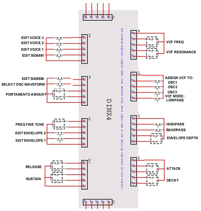
Ok, so I have to be different! I want to design a control surface that will fall somewhere between step B and step C, a CS Lite so to speak, which has dedicated controls for certain features but is less complex in terms of wiring. I am aware of the inherent lack of future proofing this entails, but i'm comfortable with that. If I ever want an expanded MBSID, i'll build another! OK, I plan to make a PCB to mount all the controls on, and then have a single DINX4 module 'plug' into it via the headers if that makes sense! To clarify, the encoders and buttons will mount on the board, and then a pair of 16-pin cables will be used to connect the DINX4 to the 'control surface lite' PCB. A similar style of connector could be used for the DOUT, although my design only requires around 17 DOUT pins, so i'm considering integrating that into the PCB. I think that would be a neat solution. The design i'm thinking of uses a single set of ADSR and envelope depth knobs, which can edit ENV1 and 2 individually or simultaneously using a pair of buttons.. It will also have VCF Freq & Q controls, and buttons to select one or more of the following: LP/BP/HP and Assign to OSC 1, 2 and 3 all of which can be selected simultaneously.There will be more buttons to select SID 1 & 2, to select which voices will be edited (3 more buttons). and to I also want a pair of encoders to adjust osc fine tune and portamento time, and a button to select oscillator waveform. An example of how i'd like this to work: Select SID 1, select all three voices, select a saw tooth wave and edit ADSR Assign all three voices to VCF Does that all make sense??? Right now, all the PCB design I can get my head around, the thing I need help with is the coding in MIOS. So far, i've been unsuccessful even getting MIOS open! I need some help, but I want to learn how to do this, i'm not asking for it to be done for me. I've got a picture of what I want to assign to the DINX4 pins but I can't upload it to Putfile for some reason. If it helps I can mail it. Right, what I need to know: 1: How to get into MIOS!! 2: Where to look for the info I need to do the code mods If anyone has done anything like this i'd like to hear from them. I don't think i've ever seen any control surface (with the exception of Der Brat, which is ace) which uses a custom config.

-
Yeah but what did he know?? ::)
-
I dig the idea of a clone, I'd love to own a real 808 for that matter as I find real boxes so inspiring. Plus the 808 just looks so fucking cool!! However, would I ever use the congas, or the dreaded cowbell? I think not! I like the more esoteric sounds that the early boxes made, like the CR8000 tambourine or the CR78 guiro for example. I'd like to clone them if I could find a nice enough schem. I too would like to combine the best sounds from the 909 and the 808 into one box to sit alongside my 55/110 voices. I think that i'd take the kick and snare from the 909 and two toms, kick, snare, clap and hats from the 808. That would be my perfect drum box I think. Of course, if it's all modular, then it should be a relative breeze to pick and choose.
-
By oscillator, I assume you mean the drum sound generator? If so that's the way i've laid out my DR-110 modules. Basically you have the Cymbal and hats on one PCB, snare on another, noise & 'Chime' on another etc... I put all the DR-55's on one board as they were so simple it would be silly to have multiple power connections. With regards to your 'weird example' I must confess that i've been thinking of something quite similiar, I guess great minds think alike! I was thinking i'd an MS-20 filter clone which has better self resonance and it's a bit more 'gritty' which works well with percussion.