ris8_allo_zen0
-
Posts
173 -
Joined
-
Last visited
Content Type
Profiles
Forums
Blogs
Gallery
Everything posted by ris8_allo_zen0
-
Sure I can... but not now, sorry! In the meanwhile, could you post the program's output (or even a graph like I did) so we can compare the results? I'm attaching the Openoffice spreadsheet to generate that graph on my post. Best regards Enrico plot.zip
-
Hello, as far as I know, the external control of the filter is made by re-routing the filter data from the internal SID's one to an analog output, so there are no new data to store in the patch. For other info, read the bottom part of the http://www.ucapps.de/mbhp_aout_lc.html page. Best regards, Enrico
-
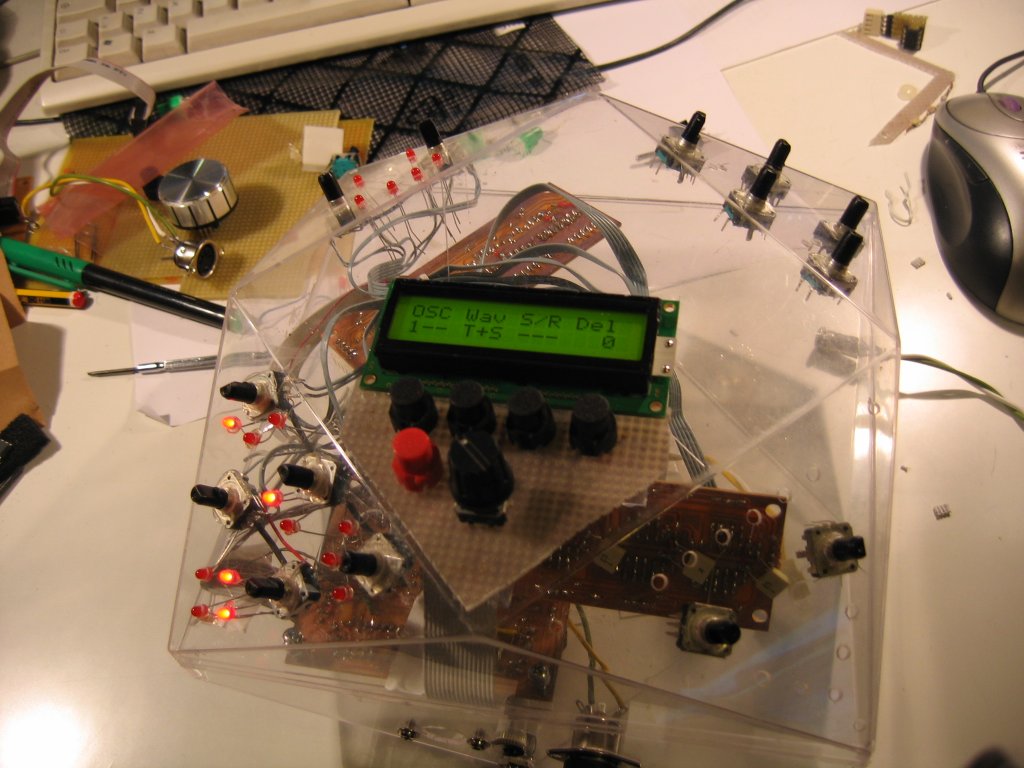
Here are some pics of the growing monster... I'm going to throw away almost all of the previous ideas because there's less "useful" space than I expected...
-
Summer of...
-
Maybe connecting the footswitches to DINs, then write a small function that sends a program change to the firmware itself? (using USER_MPROC_NotifyReceivedEvent...)
-
Maybe i haven't looked for it deeply enough in the menu options, maybe it's not quite interesting for who's slightly more experienced than me, but... I didn't find an option that forces the WT to sample the notes pressed (KEY1..KEY4) when the loop starts and to hold them during the entire loop, without stopping it if the keys are released. This way I'm not forced to change the chord I'm playing in my keyboard exactly when the loop is being finished, with the risk of making all out-of-sync (and annoying the conga-player next to me :P). I'm sure that this feature has a well-defined name which I don't know, however I hope I've explained well what I wish... Thank you very much!!
-
Sometimes it's time to get some power from our 2GHz+ beasts under the keyboard to solve everyday problems ;) Seeing that you appreciate it, I hope I can share any other solution of this kind. See you to the next creative moment!
-
I discovered that -e, -1 and -3 options were not working. They're fixed now. I also implemented a custom factor option if you still need to. Another option to implement is the possibility to output a tab- or comma-separated table: the latter is more handy with OpenOffice.org Calc (and maybe Excel too). Stay tuned! SidFilD-0.2.zip
-
Hi all, after messing with cables & pins in my Step C surface, I decided to write a simple tool to help myself writing the correct SR and Pin numbers in cs_io_tables.inc and mios_vectos.inc. It's an OpenOffice.org spreadsheet that generates the lines to be copy&paste'd to these config files. Here is what to do: 1) upload the ain64_din128_dout128_v1_3 program from the Download/Troubleshooting section of the ucapps site. 2) open the spreadsheet and choose the tab (Buttons or Encoders) you wish to work with. Notice the "DIN pin" column already filled with some numbers (it's my current configuration :) ). 3) for each button/encoder, press/rotate it and write the number displayed on the LCD (the one before the slash) to the respective row. 4) when finished, select the entire yellow box and click the Copy button. 5) open your favorite text editor, load the .inc file and go to the line specified in the cell just above the yellow box. 6) select from that point to DIN_ENTRY_EOT or ENC_EOT, included. Reference to the yellow box for an exact match. 7) do Ctrl-V in the text editor, the table should be overwritten with the new one. For safety, do some undo-redo's to check that everything is OK. 8) save, assemble and upload. 9) have fun with your custom configuration!! That's what I did for myself, however I hope it could be useful for someone building a Step C surface. I made a quick'n'dirty hack to the ain64_din128_dout128_v1_3 source to get rid of the random AIN messages. I simply inserted a return instruction just after the USER_AIN_NotifyChange label of main.asm. The source and resulting .hex are included in the zip file. DIN-ENC-config-builder.zip
-
Hi all, I've tested the filter response of my MBSID with a tool made by me (see this post: http://www.midibox.org/forum/index.php?topic=8548.0), using LP mode, no resonance and cutoff from 0 to 127. The results are in the PDF attached here. I have some doubts about the 1dB loss on all frequencies when the filter is active. Is it normal or it's a fault of my 6581R4 ? I can hear the difference and it's quite annoying for me... or at least for my unexperienced ears... I made that program just for these kind of tests on a simple PC, hoping it'll be useful to do some diagnostics to each own SIDs' filter... tell me what you think! Best regards Enrico plot_lp.pdf
-
Hi all, after two days of work I present something of interest for you. It's a little Java program that generates some typical sine waves, outputs them from the sound card, then gets the RMS level of the signal just coming from the line input. Then it presents the results in a tab-separated list to the standard output, so it can easily imported in a spreadsheet to get a graph or do some further analysis. Obviously it's a poorly-tested alpha version, written in a hurry to "see" more about the filter characteristics of my SID. However it's good to analyze the frequency response of any "black box" with an audio input and output. You can set start frequency, end frequency and the band width (1-octave or 1/3rd-octave). Before scanning frequencies, it checks for background noise RMS level (audio card & black box). You can also tell him to do just this task, if you need to. All these options are settable from the command line options (just use -h to see them). An important planned feature is the ability to control the cutoff/resonance value and filter type of a MIDIbox SID. ... and it's GPL'd :) Please try it and/or let me know what you think!! SidFilD-0.1.zip
-
I think it's the better thing to do now, because I'm new (but very fascinating about, especially for the morphing feature) to MBSEQ world... thanks a lot!!
-
If I understood correctly, you're asking why I'm so worried about robustness? If so, the answer is: encoders, leds, PCBs, screws and all sort of things are a bit heavier than a bunch of candies, and looks like this box was made to only carry the latter ones >:( Anyway, the zones near the edges seem to be quite more resistant... you can see I tried to exploit this feature as better as I can.
-
Yes, I can add some rubber blocks over the panel corners and a bigger wooden one on the side where the pivot is located. Buttons and knobs could be designed asymmetrically, without appearing "untidy" so they don't collide each other when closing the book. Indeed I never had to do with rackmounts (to tell the truth, even with step sequencers :P but a SEQ can be a good starting point, right?), but I probably will... so making a 9.5" tall book with rails can also be an idea! Yes, I was thinking about fitting the PHAT BOX (see my post in SID construction forum), a SEQ and the cables in a box 11.8" x 14.2" x 4.7" big, to use them easily at friend's homes or maybe in parties. Maybe it's a totally crazy idea but I keep dreaming until I'll pay any money...
-
Hi all, I was wondering wheter there are big problems in making a Seq like a book - splitted at half between the LCDs, and the parts joined with a pivot. It could become portable!!! Or am I reinventing the wheel?...
-
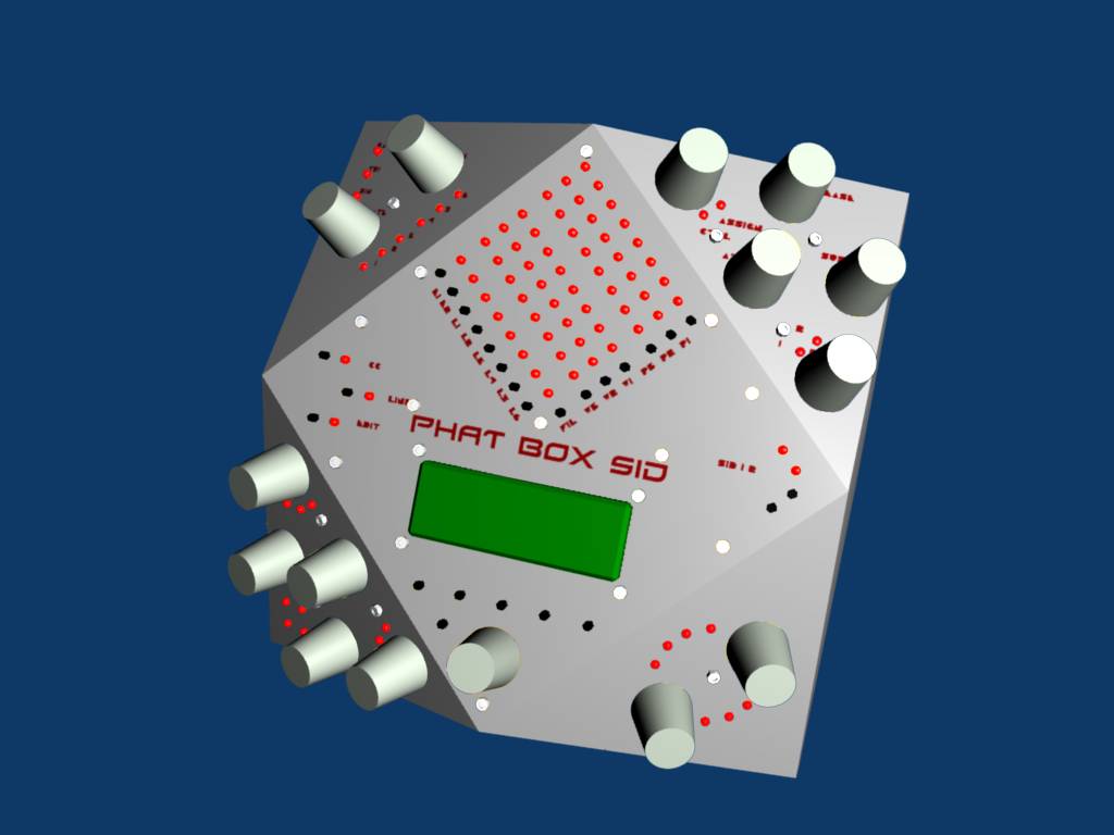
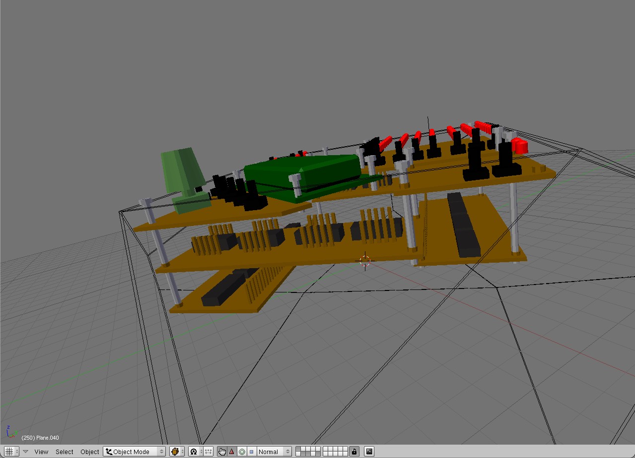
I know little about plastic matter in general, so I can't tell what type is it. It's 1mm thick and yes, I plan to paint the outside, maybe leaving some zones transparent for happyness of voyeurists :D. To reinforce the whole thing, I thought about placing a square wood or metal plate in the middle (there already was one in plastic 1.5mm thick, used to separate the candies among two levels :) ), then fix PCBs and the two valves to it with long screws. So I obtain an "endoskeleton" instead. Core and SID boards are obviously attached to it on the bottom space. Images explain it all better, compare plate.jpg with 3.jpg of my previous post. The other image shows the box name, inspired by MTE's reply :), and a painting/decal idea. I never tried UV texture painting before!! I think this will make everything more robust, but I don't know where & how much. I'm a sort-of-computer engineer, not a mechanical one ;) Uhm... I thought about putting leds inside if I find what zones to keep unpainted and transparent. My intent was to make the complete C surface, then make it a dual SID, then add the Moog VCF, then... ... yeah, MIDIbox is fun :P The candy box was produced by Ferrero, a famous Italian candy producer. I got this box two years ago for a gift, and I kept it while thinking "who knows it'll be useful later..." (I treated the original content in a much different way :D). I don't think they make similar boxes now, as you can see here: http://www.ferrero.it/main.php?w=O852GERU9GJKM6QLP3MT&path=IT/Prodotti&subpath=Prodotti/Praline/Ferrero+Rocher/Le+confezioni
-
Indeed the panels on the opposite side are less reachable and less visible, especially when the box is used in a desk while seated in front of it. But I assume I'll quickly learn the position of the knobs without visually searching for them. It's time to use the 3D sense of space of my brain :P
-
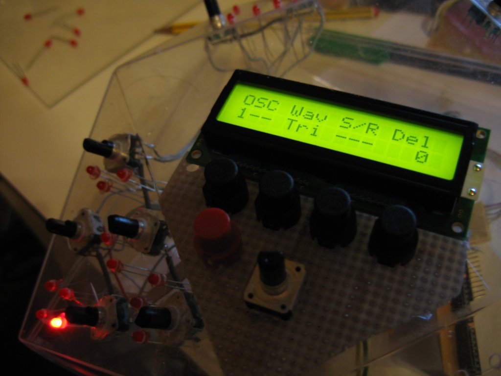
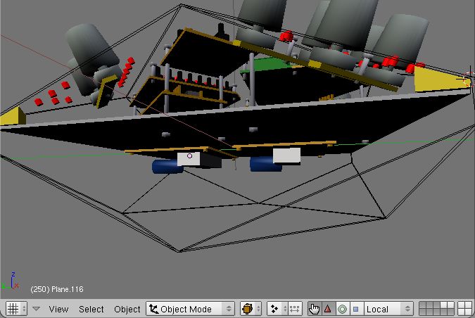
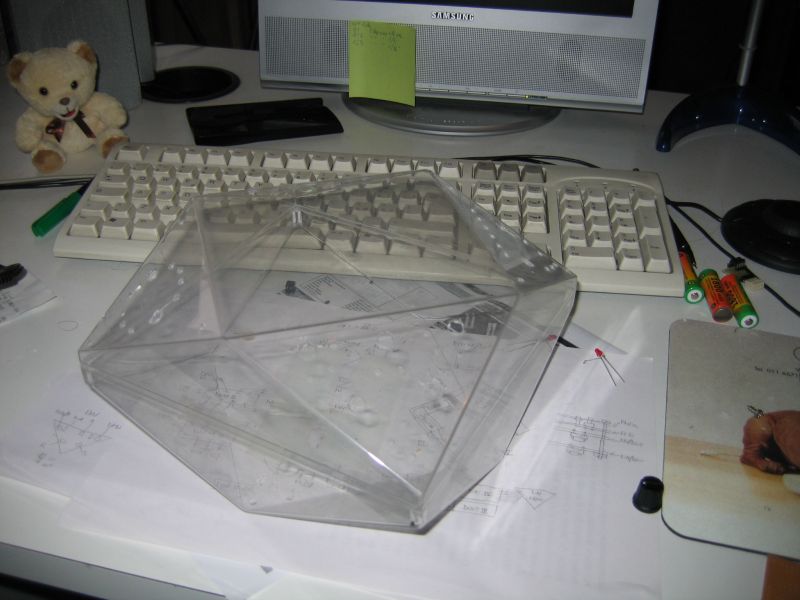
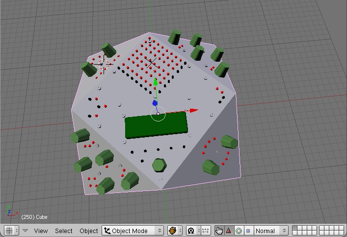
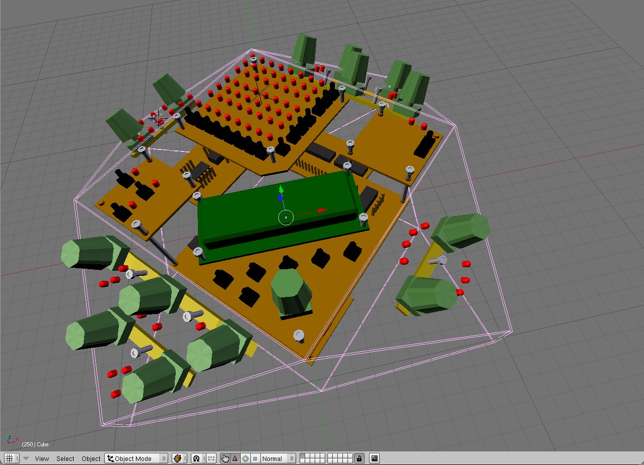
Hi all, after building a Step A MBSID inside a carton cd-walkman package (and bringing it to my university for the "audio engineering" exam - still waiting for the marks :P), I decided to go "a step beyond" - step C!! I found a very interesting casing - a plastic chocolate candy box, i.e. one of those used as a gift. It doesn't resemble any of the cases found in this forum or in the gallery, so I thought it would be of interest for you :) the first photo shows it with some holes already drilled. As you can see, it resembles a diamond - composed mainly by triangles and squares rotated by 45 degrees I think I can put in this space the complete CS in the upper half, and two cores (even four with stacking), PSU and maybe the Moog-like VCF in the lower half. The case is used as "exoskeleton" for all the boards inside, fixed through long screws to exploit the inner volume. I hope all this doesn't become too heavy to break the not-so-thick plastic!! (I'm afraid this will become a serious problem later...) I made a project using my favourite 3D modeler, Blender, used here as a CAD tool. I've attached some screenshots of it (just the upper half for now). I didn't work too much to define the position of switches/encoders/leds: i found many symmetries in the original Step C layout (e.g. two sections with 2 encoders and two with 5) so I exploited them as better as I could to have a well-balanced design. I'm quite satisfied with this result. Any comments? suggestions? ideas?
-
Dalla Germania: http://www.mikes-elektronikseite.de/shop_englisch/index.htm Dagli USA: http://www.avishowtech.com/mbhp/ I prezzi sono simili, ma suppongo che dal sito tedesco dovrai aspettare di meno per la consegna. Mentre dal sito americano i PCB sono serigrafati, il che potrebbe facilitarti il montaggio dei componenti. Insomma vedi tu :) Diciamo che x ora ho difficoltà a comprendere il concetto di "E' TARDI!" :D Enrico
-
Ciao, spero di non dirti delle stupidaggini colossali (sono un possessore di MBSID fresco di nemmeno due settimane!)... I kit che dici tu sono sicuramente le parti più importanti. Per quanto riguarda l'alimentazione, avendo il trasformatore originale del C64 devi trovarti anche i componenti relativi alla "optimized PSU" (http://www.ucapps.de/mbhp/mbhp_4xsid_c64_psu_optimized.pdf), comunque niente che tu non possa trovare in un negozio di elettronica. Non so cosa contengano esattamente i kit, ma è importante il cavetto che collega il CORE al SID... puoi cannibalizzare un cavo piatto e i relativi connettori di quelli degli hard disk IDE, sempre che il sito da cui ordini non abbia già questi pezzi pronti da montare. E non dimenticare ovviamente il PIC! ti consiglio il 18F452 che è della "matura" V2, oltretutto ha già il bootloader incluso. Poi ti suggerirei anche i cavi MIDI se non ne hai già . Ciao e buona costruzione ;) Enrico
-
SIDControl VST-plugin for MBSID V1 (not V2!) by S.M.
ris8_allo_zen0 replied to S.M.'s topic in MIDIbox SID
Hi! first of all, thank you for this great plugin! I hope I can quickly learn to use my MBSID like I wish... I have a strange problem: the plugin sends only CC messages but no notes (using Cubase)! I can hear this with the typical "pops" when I change the master SID volume, but pressing keyboard keys does anything. Midi-ox confirms all this. Where could be the problem? Many many thanks Enrico -
Why not replacing the pot with a VCA with ratio 0 to 1 driven by an AOUT? (just an idea - don't tell me how to do 8) )
-
Cannibalizing filter caps from a C64
ris8_allo_zen0 replied to ris8_allo_zen0's topic in MIDIbox SID
Thank you for all the answers. I didn't know the original C64 caps are ceramic too, I thought they were Styroflex as specified in the components orderlist. I just read about Styroflex, they "simply" have a better tolerance and quality. Fortunately, when i wrote "it looks like the filter on my mbsid isn't working" I was wrong... for some reasons I didn't update the patch parameters in JSynthlib, now I enjoy using the step A surface :P -
Hi all, I was wondering if would be possible to use the capacitors from the same C64 board where I took the SID, and if somebody already tried to do so. (this question arose because it looks like the filter on my mbsid isn't working... and I didn't find those "Styroflex" caps, only ceramic ones) I don't have a board here so I can't tell by myself... Many thanks! Enrico
-
Another working MBSID :D and some questions...
ris8_allo_zen0 replied to ris8_allo_zen0's topic in MIDIbox SID
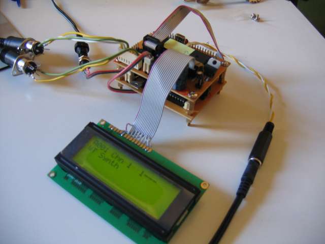
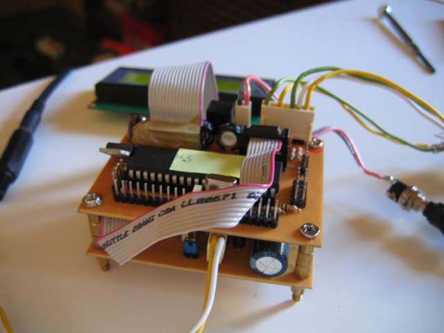
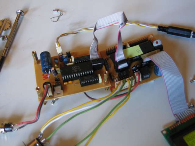
Sure! They're attached in the post. As you can see, I tried to stack the boards using those nuts-bolts used to mount PC motherboards... and I'm quite satisfied with the result. I had to lay down the 2200uF cap of the Sid module to reduce overall height: there's enough room on the board to do this, was it TK's intention?? I obtained the ribbon cables and IDC connectors by cutting and "sawing" from old IDE/floppy cables... I can easily make connectors the size I like, but they're not as robust as the original ones :( :o I think it's a good reason to look for another solution... The problem is that I don't have one here :-[ and I have some difficulties finding one among my friends... I also read something about it but I found no other docs... OK, I'll work on it sooner or later... Enrico