
julienvoirin
-
Posts
790 -
Joined
-
Last visited
-
Days Won
3
Content Type
Profiles
Forums
Blogs
Gallery
Posts posted by julienvoirin
-
-
here is the final applications
moreover i did a controller on arduino/ethernet/wifi and iPad/touchOSC for Roland Juno2
ARDUINO CODE for Juno2 sysex translator :
////////////////////////////////////////////////////////////////////// // OSCClass iOSC(iPhone App) test sketch // OSCClass version 1.0.1 (Arduino ver0014) // Copyright (c) recotana(http://recotana.com). All right reserved. ////////////////////////////////////////////////////////////////////// /* TouchOSC is OSCsend Application for iPad OSC setting example : OSCMessage type value on off button1 /Juno2/button_name float 1 0 :info-AlternateMode "ON" = toggle sw slider1 /Juno2/button_name float 1 0 Arduino setting IP address 192.168.1.10 , incoming port : 8000 (server) Arduino setting IP address 192.168.1.10 , outgoing port : 8008 iPad setting IP address 192.168.1.4 , incoming port : 8008 (client) iPad setting IP address 192.168.1.4 , outgoing port : 8000 Parameters on the Juno2 : I. First scroll through the MIDI menu and turn Exclusive Messages ON. II. These are the components of the system exclusive message: F0 [Exclusive] 41 [Roland ID#] 36 [Individual Tone Parameters] 0N [N=MIDI channel (N=0-F, Chan 1=00 Chan 16=0F)] 23 [Format type] 20 [unknown] 01 [unknown] XX [Parameter number (0-23)] see table below YY [Value (0-127)] Can be left at 00 F7 [End of Exclusive] III. Here is an example: A SysEx message for editing the VCF Resonance Parameter on MIDI channel 1: F0 41 36 00 23 20 01 11 00 F7 "11" Is the SysEx code for the VCF Resonance edit parameter. "00" Is the SysEx code for the variable start value of the current edit parameter. Parameter Numbers (XX) For The Alpha Juno Synths: 37 parameters (Parentheses indicated range of variable values 'YY' possible for the parameter.) CODE (XX) EDIT PARAMETER COMPLETE SYSEX CODE CC# 00 DCO Env. Mode (0=Normal, 1=Inverted, 2=Normal-Dynamic, 3=Inv.-Dynamic) F0 41 36 00 23 20 01 00 00 F7 84 01 VCF Env. Mode (0=Normal, 1=Inverted, 2=Normal-Dynamic, 3=Dynamic) F0 41 36 00 23 20 01 01 00 F7 85 02 VCA Env. Mode (0=Normal, 1=Gate, 2=Normal-Dynamic, 3=Gate-Dynamic) F0 41 36 00 23 20 01 02 00 F7 86 03 DCO Wave Pulse (0..3) F0 41 36 00 23 20 01 03 00 F7 87 04 DCO Wave Saw (0..5) F0 41 36 00 23 20 01 04 00 F7 88 05 DCO Wave Sub (0..5) F0 41 36 00 23 20 01 05 00 F7 89 06 DCO Range (0=4', 1=8', 2=16', 3=32') F0 41 36 00 23 20 01 06 00 F7 90 07 DCO Sub Level (0..3) F0 41 36 00 23 20 01 07 00 F7 91 08 DCO Noise (0..3) F0 41 36 00 23 20 01 08 00 F7 92 09 HPF Cutoff (0..3) F0 41 36 00 23 20 01 09 00 F7 93 0A Chorus Switch (0=Off, 1=On) F0 41 36 00 23 20 01 0A 00 F7 94 0B DCO LFO Mod. (0..7F) F0 41 36 00 23 20 01 0B 00 F7 95 0C DCO ENV Mod. (0..7F) F0 41 36 00 23 20 01 0C 00 F7 96 0D DCO After Mod. (0..7F) F0 41 36 00 23 20 01 0D 00 F7 97 0E DCO PWM Depth (0..7F) F0 41 36 00 23 20 01 0E 00 F7 98 0F DCO PWM Rate (0..7F) 0 = Pulse Width Manual 1..7F = PW LFO Rate F0 41 36 00 23 20 01 0F 00 F7 99 10 VCF Cutoff (0..7F) F0 41 36 00 23 20 01 10 00 F7 100 11 VCF Resonance (0..7F) F0 41 36 00 23 20 01 11 00 F7 101 12 VCF LFO Mod. (0..7F) F0 41 36 00 23 20 01 12 00 F7 102 13 VCF ENV Mod. (0..7F) F0 41 36 00 23 20 01 13 00 F7 103 14 VCF Key Follow (0..7F) F0 41 36 00 23 20 01 14 00 F7 104 15 VCF Aftertouch (0..7F) F0 41 36 00 23 20 01 15 00 F7 105 16 VCA Level (0..7F) F0 41 36 00 23 20 01 16 00 F7 106 17 VCA Aftertouch (0..7F) F0 41 36 00 23 20 01 17 00 F7 107 18 LFO Rate (0..7F) F0 41 36 00 23 20 01 18 00 F7 108 19 LFO Delay (0..7F) F0 41 36 00 23 20 01 19 00 F7 109 1A ENV T1 (0..7F) Attack Time F0 41 36 00 23 20 01 1A 00 F7 110 1B ENV L1 (0..7F) Attack Level F0 41 36 00 23 20 01 1B 00 F7 111 1C ENV T2 (0..7F) Break Time F0 41 36 00 23 20 01 1C 00 F7 112 1D ENV L2 (0..7F) Break Level F0 41 36 00 23 20 01 1D 00 F7 113 1E ENV T3 (0..7F) Decay Time F0 41 36 00 23 20 01 1E 00 F7 114 1F ENV L3 (0..7F) Sustain Level F0 41 36 00 23 20 01 1F 00 F7 115 20 ENV T4 (0..7F) Release Time F0 41 36 00 23 20 01 20 00 F7 116 21 ENV Key Follow (0..78) F0 41 36 00 23 20 01 21 00 F7 117 22 Chorus Rate (0..7F) F0 41 36 00 23 20 01 22 00 F7 118 23 Bender Range (0..C) F0 41 36 00 23 20 01 23 00 F7 119 */ #include "Ethernet.h" #include <OSCClass_018.h> #include "MIDI.h" #define _POT_DEBUG_ 0 // set to 1 to debug with pot #define LED_PWM 6 // red led of midi shield #define POT_PIN 0 #define SW_PIN 3 #define note_offset 36 #define midi_channel 1 OSCMessage recMes; OSCMessage sendMes; OSCClass osc(&recMes); // server cfg (arduino) byte serverMac[] = { 0xDE, 0xAD, 0xBE, 0xEF, 0xFE, 0xED }; byte serverIp[] = { // arduino IP 192, 168, 0, 13 }; int serverPort = 8000; // outgoing from iPad, incoming to arduino // byte gateway[] = { 192, 168, 1, 2 }; // byte subnet[] = { 255, 255, 255, 0 }; // client cfg byte destIp[] = { 192, 168, 0, 19}; // iPad IP int destPort = 8008; // outgoing from arduino, incoming to iPad char *Juno2_OSC_name[3] = { "/jun", "/note", "/ctrl" }; char *Juno2_OSC_param_name[37] = { // 36 parameters "/DCO_Env_Mode", // $00 "/VCF_Env_Mode", // $01 "/VCA_Env_Mode", // $02 "/DCO_Wave_Pulse", // $03 "/DCO_Wave_Saw", // $04 "/DCO_Wave_Sub", // $05 "/DCO_Range", // $06 "/DCO_Sub_Level", // $07 "/DCO_Noise_Level",// $08 "/HPF_CutOff", // $09 "/Chorus_Switch", // $0a "/DCO_Lfo_Mod", // $0b "/DCO_Env_Mod", // $0c "/DCO_After_Mod", // $0d "/DCO_Pwm_Depth", // $0e "/DCO_Pwm_Rate", // $0f "/VCF_CutOff", // $10 d16 "/VCF_Resonance", // $11 "/VCF_Lfo_Mod", // $12 "/VCF_Env_Mod", // $13 "/VCF_Key_Follow", // $14 "/VCF_Aftertouch", // $15 "/VCA_Level", // $16 "/VCA_Aftertouch", // $17 "/LFO_Rate", // $18 "/LFO_Delay", // $19 "/ENV_T1", // $1a "/ENV_L1", // $1b "/ENV_T2", // $1c "/ENV_L2", // $1d "/ENV_T3", // $1e "/ENV_L3", // $1f "/ENV_T4", // $20 "/ENV_Key_Follow", // $21 "/Chorus_Rate", // $22 "/Bender_Range", // $23 }; // Arrays of patch parameters values byte Juno2_SysEx_Patch_APR[54]; // whole patch byte Juno2_SysEx_Patch_IPR[10]; // single parameter char *midi_note[12] = { "/key_0", "/key_1", "/key_2", "/key_3", "/key_4", "/key_5", "/key_6", "/key_7", "/key_8", "/key_9", "/key_10", "/key_11",/* "/key_12", "/key_13", "/key_14", "/key_15", "/key_16", "/key_17", "/key_18", "/key_19", "/key_20", "/key_21", "/key_22", "/key_23", "/key_24", "/key_25", "/key_26", "/key_27", "/key_28", "/key_29", "/key_30", "/key_31", "/key_32", "/key_33", "/key_34", "/key_35", "/key_36", "/key_37", "/key_38", "/key_39", "/key_40", "/key_41", "/key_42", "/key_43", "/key_44", "/key_45", "/key_46", "/key_47", "/key_48", "/key_49", */ }; // pot, led & switch flags boolean ledFlag; boolean swFlag; long oldPotValue; ////////////////////////////////////////////////// // Init ////////////////////////////////////////////////// void setup() { // set midi baudsrate // Serial.begin(31250); // old method without midi.h --> don't use // Serial.print("reset"); // Initiate MIDI communications, listen to all channels MIDI.begin(MIDI_CHANNEL_OMNI); // Connect the HandleSysex function to the library, so it is called upon reception of a sysex. MIDI.setHandleSystemExclusive(HandleSystemExclusive); // Put only the name of the function Ethernet.begin(serverMac ,serverIp); // Ethernet.begin(serverMac ,serverIp ,gateway ,subnet); // setting osc recieve server osc.begin(serverPort); // init osc send < --- pose pb si logMessage est compilé sendMes.setIp( destIp ); sendMes.setPort( destPort ); // LED OFF pinMode(LED_PWM, OUTPUT); digitalWrite(LED_PWM, HIGH); // switch and pot pinMode(SW_PIN, INPUT); ledFlag = false; swFlag = false; analogReference(DEFAULT); oldPotValue = (long)analogRead(POT_PIN); // osc message buffer clear osc.flush(); } ///////////////////////////////////////////////////// // Mainloop ///////////////////////////////////////////////////// void loop() { // osc arrive check if ( osc.available() ){ OSC_SYSEX(); OSC_NOTE(recMes); } else{ // } // midi arrive check if (MIDI.read()) { // Is there a MIDI message incoming ? switch(MIDI.getType()) { // Get the type of the message we caught case SystemExclusive: // If it is a sysex SYSEX_OSC( MIDI.getData1(), MIDI.getSysExArray() ); // call SYSEX_OSC function break; // See the online reference for other message types default: break; } } #ifdef _POT_DEBUG_ // pot active send VCF CutOff POT_OSC(); #endif } ///////////////////////////////////////////////////////// // ///////////////////////////////////////////////////////// void HandleSystemExclusive(byte *array, byte size) { } /////////////////////////////////////////////////////// // Convert OSC to Sysex /////////////////////////////////////////////////////// void OSC_SYSEX(void) { // toplevel address matching if( !strcmp( recMes.getAddress(0) , Juno2_OSC_name[0] ) ){ // "/jun" // second level address matching if( !strcmp( recMes.getAddress(1) , Juno2_OSC_param_name[0] ) ){ MIDI_SEND_IPR(0, recMes.getArgFloat(0)); } else if(!strcmp( recMes.getAddress(1) , Juno2_OSC_param_name[1])){ MIDI_SEND_IPR(1, recMes.getArgFloat(0)); } else if(!strcmp( recMes.getAddress(1) , Juno2_OSC_param_name[2])){ MIDI_SEND_IPR(2, recMes.getArgFloat(0)); } else if(!strcmp( recMes.getAddress(1) , Juno2_OSC_param_name[3])){ MIDI_SEND_IPR(3, recMes.getArgFloat(0)); } else if(!strcmp( recMes.getAddress(1) , Juno2_OSC_param_name[4])){ MIDI_SEND_IPR(4, recMes.getArgFloat(0)); } else if(!strcmp( recMes.getAddress(1) , Juno2_OSC_param_name[5])){ MIDI_SEND_IPR(5, recMes.getArgFloat(0)); } else if(!strcmp( recMes.getAddress(1) , Juno2_OSC_param_name[6])){ MIDI_SEND_IPR(6, recMes.getArgFloat(0)); } else if(!strcmp( recMes.getAddress(1) , Juno2_OSC_param_name[7])){ MIDI_SEND_IPR(7, recMes.getArgFloat(0)); } else if(!strcmp( recMes.getAddress(1) , Juno2_OSC_param_name[8])){ MIDI_SEND_IPR(8, recMes.getArgFloat(0)); } else if(!strcmp( recMes.getAddress(1) , Juno2_OSC_param_name[9])){ MIDI_SEND_IPR(9, recMes.getArgFloat(0)); } else if(!strcmp( recMes.getAddress(1) , Juno2_OSC_param_name[10])){ MIDI_SEND_IPR(10, recMes.getArgFloat(0)); } else if(!strcmp( recMes.getAddress(1) , Juno2_OSC_param_name[11])){ MIDI_SEND_IPR(11, recMes.getArgFloat(0)); } else if(!strcmp( recMes.getAddress(1) , Juno2_OSC_param_name[12])){ MIDI_SEND_IPR(12, recMes.getArgFloat(0)); } else if(!strcmp( recMes.getAddress(1) , Juno2_OSC_param_name[13])){ MIDI_SEND_IPR(13, recMes.getArgFloat(0)); } else if(!strcmp( recMes.getAddress(1) , Juno2_OSC_param_name[14])){ MIDI_SEND_IPR(14, recMes.getArgFloat(0)); } else if(!strcmp( recMes.getAddress(1) , Juno2_OSC_param_name[15])){ MIDI_SEND_IPR(15, recMes.getArgFloat(0)); } else if(!strcmp( recMes.getAddress(1) , Juno2_OSC_param_name[16])){ MIDI_SEND_IPR(16, recMes.getArgFloat(0)); } else if(!strcmp( recMes.getAddress(1) , Juno2_OSC_param_name[17])){ MIDI_SEND_IPR(17, recMes.getArgFloat(0)); } else if(!strcmp( recMes.getAddress(1) , Juno2_OSC_param_name[18])){ MIDI_SEND_IPR(18, recMes.getArgFloat(0)); } else if(!strcmp( recMes.getAddress(1) , Juno2_OSC_param_name[19])){ MIDI_SEND_IPR(19, recMes.getArgFloat(0)); } else if(!strcmp( recMes.getAddress(1) , Juno2_OSC_param_name[20])){ MIDI_SEND_IPR(20, recMes.getArgFloat(0)); } else if(!strcmp( recMes.getAddress(1) , Juno2_OSC_param_name[21])){ MIDI_SEND_IPR(21, recMes.getArgFloat(0)); } else if(!strcmp( recMes.getAddress(1) , Juno2_OSC_param_name[22])){ MIDI_SEND_IPR(22, recMes.getArgFloat(0)); } else if(!strcmp( recMes.getAddress(1) , Juno2_OSC_param_name[23])){ MIDI_SEND_IPR(23, recMes.getArgFloat(0)); } else if(!strcmp( recMes.getAddress(1) , Juno2_OSC_param_name[24])){ MIDI_SEND_IPR(24, recMes.getArgFloat(0)); } else if(!strcmp( recMes.getAddress(1) , Juno2_OSC_param_name[25])){ MIDI_SEND_IPR(25, recMes.getArgFloat(0)); } else if(!strcmp( recMes.getAddress(1) , Juno2_OSC_param_name[26])){ MIDI_SEND_IPR(26, recMes.getArgFloat(0)); } else if(!strcmp( recMes.getAddress(1) , Juno2_OSC_param_name[27])){ MIDI_SEND_IPR(27, recMes.getArgFloat(0)); } else if(!strcmp( recMes.getAddress(1) , Juno2_OSC_param_name[28])){ MIDI_SEND_IPR(28, recMes.getArgFloat(0)); } else if(!strcmp( recMes.getAddress(1) , Juno2_OSC_param_name[29])){ MIDI_SEND_IPR(29, recMes.getArgFloat(0)); } else if(!strcmp( recMes.getAddress(1) , Juno2_OSC_param_name[30])){ MIDI_SEND_IPR(30, recMes.getArgFloat(0)); } else if(!strcmp( recMes.getAddress(1) , Juno2_OSC_param_name[31])){ MIDI_SEND_IPR(31, recMes.getArgFloat(0)); } else if(!strcmp( recMes.getAddress(1) , Juno2_OSC_param_name[32])){ MIDI_SEND_IPR(32, recMes.getArgFloat(0)); } else if(!strcmp( recMes.getAddress(1) , Juno2_OSC_param_name[33])){ MIDI_SEND_IPR(33, recMes.getArgFloat(0)); } else if(!strcmp( recMes.getAddress(1) , Juno2_OSC_param_name[34])){ MIDI_SEND_IPR(34, recMes.getArgFloat(0)); } else if(!strcmp( recMes.getAddress(1) , Juno2_OSC_param_name[35])){ MIDI_SEND_IPR(35, recMes.getArgFloat(0)); } else if(!strcmp( recMes.getAddress(1) , Juno2_OSC_param_name[36])){ MIDI_SEND_IPR(36, recMes.getArgFloat(0)); } else if(!strcmp( recMes.getAddress(1) , Juno2_OSC_param_name[37])){ MIDI_SEND_IPR(37, recMes.getArgFloat(0)); } else if(!strcmp( recMes.getAddress(1) , Juno2_OSC_param_name[37])){ MIDI_SEND_IPR(37, recMes.getArgFloat(0)); } else{ // rien } } else if( !strcmp( recMes.getAddress(0) , Juno2_OSC_name[1] ) ){ // Note On OSC message } else{ // to complete } } ////////////////////////////////////////////////////////////// // Send Juno2 SysEx string ////////////////////////////////////////////////////////////// void MIDI_SEND_IPR( char osc_param_name, double osc_param_value) { //byte sysex_param_value = (byte)osc_param_value; // transform that shit ! // visual feedback LED analogWrite(LED_PWM, floor(255 - osc_param_value)); // set IPR sysex bytes : F0 41 36 00 23 20 01 name value F7 Juno2_SysEx_Patch_IPR[0] = 0xf0; Juno2_SysEx_Patch_IPR[1] = 0x41; Juno2_SysEx_Patch_IPR[2] = 0x36; Juno2_SysEx_Patch_IPR[3] = 0x00; Juno2_SysEx_Patch_IPR[4] = 0x23; Juno2_SysEx_Patch_IPR[5] = 0x20; Juno2_SysEx_Patch_IPR[6] = 0x01; Juno2_SysEx_Patch_IPR[7] = (byte)osc_param_name; Juno2_SysEx_Patch_IPR[8] = (byte)osc_param_value; // sysex_param_value Juno2_SysEx_Patch_IPR[9] = 0xf7; // send 10 bytes sysex array, including F0 & F7 (true) MIDI.sendSysEx( 10, Juno2_SysEx_Patch_IPR, true ); // ça marche :) } /////////////////////////////////////////////////////// // convert SYSEX in OSC /////////////////////////////////////////////////////// void SYSEX_OSC( byte size, byte *sysex_array ) { // if it is a 54 bytes sysex string = APR if (size == 54){ for (char i=0; i<55; i++) Juno2_SysEx_Patch_APR[i] = sysex_array[i]; // extract param values from sysex // convert APR to 38xIPR message for (char p=0; p<39; p++){ sendMes.setTopAddress(Juno2_OSC_name[0]); // "/jun" sendMes.setSubAddress( (char*)Juno2_OSC_param_name[p] ); // e.g "/VCF_CutOff" float f = sysex_array[ 7 + p ] + 0.000; // transform to float shit sendMes.setArgs( "f", &(f) ); osc.sendOsc( &sendMes ); delay(10); // small delay to see faders moving ;) } } // if it is a 38 bytes sysex string = not implemented else if (size == 38){ // do stuff } // if it is a 10 bytes sysex string = IPR else if (size == 10){ // transform array for (char j=0; j<11; j++) Juno2_SysEx_Patch_IPR[j] = sysex_array[j]; //OSC send IPR sendMes.setTopAddress(Juno2_OSC_name[0]); // "/jun" sendMes.setSubAddress( (char*)Juno2_OSC_param_name[Juno2_SysEx_Patch_IPR[7]] ); // e.g "//VCF_CutOff" float f = Juno2_SysEx_Patch_IPR[8] + 0.000; // convert in float sendMes.setArgs( "f", &(f) ); // e.g "120." osc.sendOsc( &sendMes ); } } #ifdef _POT_DEBUG_ //////////////////////////////////////////////////// // Convert POT to OSC VCF_CutOff message ///////////////////////////////////////////////////// void POT_OSC(void) { int pot=analogRead(POT_PIN); //adc data = 10bit data long value = (long)(pot >> 3); // 1024 -> 127 if( oldPotValue != value ){ sendMes.setTopAddress(Juno2_OSC_name[0]); sendMes.setSubAddress(Juno2_OSC_param_name[16] ); // "/jun/VCF_CutOff" sendMes.setArgs( "i", &value ); osc.sendOsc( &sendMes ); // Serial.print("pot:"); // Serial.println(value); } oldPotValue = value; } #endif //////////////////////////////////////////////////// // Convert OSC Note message ///////////////////////////////////////////////////// void OSC_NOTE(OSCMessage recMes) { // toplevel address matching if( !strcmp( recMes.getAddress(0) , Juno2_OSC_name[1] ) ){ // "/note" // second level address matching for(char k=0; k<12; k++){ if( !strcmp( recMes.getAddress(1) , midi_note[k] ) ){ MIDI.sendNoteOn((byte)( k + note_offset), (byte)recMes.getArgFloat(0), midi_channel); //MIDI.sendNoteOn((byte)(i + 60), (byte)recMes.getArgFloat(0), 1); } } } } ////////////////////////////////////////////////////// //// Send Note from OSC /////////////////////////////////////////////////////// //void MIDI_SEND_NOTE(long note, double velocity) //{ // MIDI.sendNoteOn((byte)note, (byte)velocity, 1); //} -
a performance from my own band
classe !
-
-
that's what is expected ! you also need too see the right pin ?? i had understood that you only needed the right CC on midi OUTfor A5 A6 and A7 the LCD looks buggy,
of course ! it displays the midi messages SENT TO the midi box (midi in)5 - DOUT part of the LCD is not showing events (not very important)change the value of HIGH and LOW in main.h for (HIGH = 1, LOW = 0)
change this :
/////////////////////////////////////////////////////////////////////////////

// This function is called by MIOS when an button has been toggled

// pin_value is 1 when button released, and 0 when button pressed

/////////////////////////////////////////////////////////////////////////////

void DIN_NotifyToggle(unsigned char pin, unsigned char pin_value) __wparam

{

        // http://www.arduino.cc/en/Tutorial/Switch

        // if the input just went from LOW and HIGH, toggle the output pin


        reading = pin_value;


        if ( reading == HIGH && previous == LOW) { // buttons are high-active

                if (state == HIGH){

                        state = LOW;

                }

                else{

                        state = HIGH;

                }

        }


        // digitalWrite(outPin, state);

        MIOS_MIDI_BeginStream();

        MIOS_MIDI_TxBufferPut(0x90); // Note at channel 1

        MIOS_MIDI_TxBufferPut(pin);  // pin number corresponds to note number

        MIOS_MIDI_TxBufferPut(state *127);  //  to multiply x127

        MIOS_MIDI_EndStream();


        // toggle LED corresponding to pin

        MIOS_DOUT_PinSet( pin, state);


         previous = reading;


  // notify display handler in DISPLAY_Tick() that DIN value has changed

  last_din_pin = pin;

  app_flags.DISPLAY_UPDATE_REQ = 1;

}
put this in initialise data section :///////////////////////////////////////////////////////////////////////////// // Local variables ///////////////////////////////////////////////////////////////////////////// // last ain/din/dout unsigned char last_ain_pin; unsigned char last_din_pin; unsigned char last_dout_pin; int state = HIGH; // the current state of the output pin int reading; // the current reading from the input pin int previous = LOW; // the previous reading from the input pinand recompile the app of course
-
the pin A7 of j5B gives nothing (it should expect 48 isn't it ?)
the pin A6 of j5B gives 48 (it should expect 40 isn't it ?)
the pin A5 of j5B gives 40 (it should expect 32 isn't it )?
OK my fault. we count from A0 so ... (i count from A1 like a stupid boy)
         case 31: // 32nd pot

                case 40: // pin A5

                case 48: // pin A6

                case 56: // pin A7

                        // a pot has been moved, send CC#<pin-number> at channel 1

                        MIOS_MIDI_BeginStream();

                        MIOS_MIDI_TxBufferPut(0xb0); // CC at channel 1

                        MIOS_MIDI_TxBufferPut(pin);  // pin number corresponds to CC number

                        MIOS_MIDI_TxBufferPut(MIOS_AIN_Pin7bitGet(pin)); // don't send 10bit pin_value, but 7bit value

                        MIOS_MIDI_EndStream();

                        break;
parenthesis problem modified code2 - Leds are light ... 3 - the LCD don't show events///////////////////////////////////////////////////////////////////////////// // This function is called by MIOS when an button has been toggled // pin_value is 1 when button released, and 0 when button pressed ///////////////////////////////////////////////////////////////////////////// void DIN_NotifyToggle(unsigned char pin, unsigned char pin_value) __wparam { // http://www.arduino.cc/en/Tutorial/Switch // if the input just went from LOW and HIGH, toggle the output pin int state = HIGH; // the current state of the output pin int reading; // the current reading from the input pin int previous = LOW; // the previous reading from the input pin reading = pin_value; if ( reading == HIGH && previous == LOW) { // buttons are high-active if (state == HIGH){ state = LOW; } else{ state = HIGH; } } // digitalWrite(outPin, state); MIOS_MIDI_BeginStream(); MIOS_MIDI_TxBufferPut(0x90); // Note at channel 1 MIOS_MIDI_TxBufferPut(pin); // pin number corresponds to note number MIOS_MIDI_TxBufferPut(state << 3); // bitshifting to multiply x127 MIOS_MIDI_EndStream(); previous = reading; // toggle LED corresponding to pin MIOS_DOUT_PinSet( pin, state); // notify display handler in DISPLAY_Tick() that DIN value has changed last_din_pin = pin; app_flags.DISPLAY_UPDATE_REQ = 1; } ///////////////////////////////////////////////////////////////////////////// // This function is called by MIOS when an encoder has been moved // incrementer is positive when encoder has been turned clockwise, else // it is negative ///////////////////////////////////////////////////////////////////////////// void ENC_NotifyChange(unsigned char encoder, char incrementer) __wparam { } ///////////////////////////////////////////////////////////////////////////// // This function is called by MIOS when a pot has been moved ///////////////////////////////////////////////////////////////////////////// void AIN_NotifyChange(unsigned char pin, unsigned int pin_value) __wparam { switch (pin){ case 0: // = 1st pot ^^ case 1: case 2: case 3: case 4: case 5: case 6: case 7: case 8: case 9: case 10: case 11: case 12: case 13: case 14: case 15: case 16: case 17: case 18: case 19: case 20: case 21: case 22: case 23: case 24: case 25: case 26: case 27: case 28: case 29: case 30: case 31: // 32nd pot case 40: // pin A5 case 48: // pin A6 case 56: // pin A7 // a pot has been moved, send CC#<pin-number> at channel 1 MIOS_MIDI_BeginStream(); MIOS_MIDI_TxBufferPut(0xb0); // CC at channel 1 MIOS_MIDI_TxBufferPut(pin); // pin number corresponds to CC number MIOS_MIDI_TxBufferPut(MIOS_AIN_Pin7bitGet(pin)); // don't send 10bit pin_value, but 7bit value MIOS_MIDI_EndStream(); break; default: // all other pots and ain // do nothing break; } // notify display handler in DISPLAY_Tick() that AIN value has changed last_ain_pin = pin; app_flags.DISPLAY_UPDATE_REQ = 1; } -
I think it is parenthesis problems. i will check later
-
Here is my idea
1 - pin A5 to A7 each should gives only one CC : I don't guess where to put the switch/cases you suggest julienvoirin///////////////////////////////////////////////////////////////////////////// // This function is called by MIOS when a pot has been moved ///////////////////////////////////////////////////////////////////////////// void AIN_NotifyChange(unsigned char pin, unsigned int pin_value) __wparam { switch (pin){ case 0: // = 1st pot ^^ case 1: case 2: case 3: case 4: case 5: case 6: case 7: case 8: case 9: case 10: case 11: case 12: case 13: case 14: case 15: case 16: case 17: case 18: case 19: case 20: case 21: case 22: case 23: case 24: case 25: case 26: case 27: case 28: case 29: case 30: case 31: // 32nd pot case 32: // pin A5 case 40: // pin A6 case 48: // pin A7 // a pot has been moved, send CC#<pin-number> at channel 1 MIOS_MIDI_BeginStream(); MIOS_MIDI_TxBufferPut(0xb0); // CC at channel 1 MIOS_MIDI_TxBufferPut(pin); // pin number corresponds to CC number MIOS_MIDI_TxBufferPut(MIOS_AIN_Pin7bitGet(pin)); // don't send 10bit pin_value, but 7bit value MIOS_MIDI_EndStream(); break; default: // all other pots and ain // do nothing break; // notify display handler in DISPLAY_Tick() that AIN value has changed last_ain_pin = pin; app_flags.DISPLAY_UPDATE_REQ = 1; } }2 - Buttons set to the toogle mode : is there a solution to set this directly in the app code ?///////////////////////////////////////////////////////////////////////////// // This function is called by MIOS when an button has been toggled // pin_value is 1 when button released, and 0 when button pressed ///////////////////////////////////////////////////////////////////////////// void DIN_NotifyToggle(unsigned char pin, unsigned char pin_value) __wparam { // http://www.arduino.cc/en/Tutorial/Switch // if the input just went from LOW and HIGH, toggle the output pin int state = HIGH; // the current state of the output pin int reading; // the current reading from the input pin int previous = LOW; // the previous reading from the input pin reading = pin_value; if ( reading == HIGH && previous == LOW) { // buttons are high-active if (state == HIGH){ state = LOW; } else{ state = HIGH; } // digitalWrite(outPin, state); MIOS_MIDI_BeginStream(); MIOS_MIDI_TxBufferPut(0x90); // Note at channel 1 MIOS_MIDI_TxBufferPut(pin); // pin number corresponds to note number MIOS_MIDI_TxBufferPut(state << 3); // bitshifting to multiply x127 MIOS_MIDI_EndStream(); previous = reading; } // toggle LED corresponding to pin MIOS_DOUT_PinSet( pin, state); // notify display handler in DISPLAY_Tick() that DIN value has changed last_din_pin = pin; app_flags.DISPLAY_UPDATE_REQ = 1; }3 - associate DIN pins 17 to 24 to the DOUT pins 17 to 24 : I admit that// toggle LED corresponding to pin MIOS_DOUT_PinSet( pin, state);
please try the .hex and tell me if it does what expected
-
to associate the DIN and DOUT pins to light up the leds when I press the buttons
easy ! use an array if neccessary for cpxe routines
-
maybe he can switch to the ain64din128dout128 app ... that's the only solution I see
best regards
-
edit C code area of AIN and use a switch/case routine. for Case 0 -> Case 31, leave the code,
for case 32 : this is your first pot
for case 32+8 = 40 : this is your second pot
for case 32+8 +8 = 48 : this is your third pot
for "default" type a return code string
-
that's clearly an awesome job ; unfortunatly I can't use it as I've a Powermac G5 and ctrlr app seems made for Intel with 10.6. If someone has a trick, it is welcome :thumbsup:
-
AOUT NG design is buggy in dual mod. you can't have +/- 5V but only the half : it's mentioned in the forum somewhere but i can't find
-
a detent pot has a switch at the very low end
e.g : a cheap radio receiver - volume is controlled by the pot and at the very low end, it is the power on/off switch
6 pins pot = 2 pots in parallel. usage : stereo or dual circuit
-
thanks for your prompt answer Gilesjuk :)
If i well undertand, you call "pad" what i call electrodes : yes there are still is place, there are 3 groups of electrod on 3 sides so that you can cut the EL foil to fit your design
-
Dear Boxers
I need your help, really, as i am not familiar with the electroluminescent (EL) technology
I have a Yamaha REV7 with a very old LCD (Hitachi 44780 driver). The backlight is dead. It is not a LED backlight but a sheet of EL material.
So i bought a EL sheet on ebay to replace it. When the sheet arrived i tested it by connecting it to the inverter and it has glowed. But the sheet was too big, so I cut it to the good dimensions.
But after, the EL was no more glowing (??? wtf !!).
I measured the output of the inverter : a pseudo sinusal 150V AC @ 222 Hz
1 - is the inverter dead ? (it transforms 5V DC in 150 AC)
2 - is he EL foil dead ? i cut it with scissors
the sheet is similar to this one :
http://www.elec2go.com.au/images/el%20cuttbale%20panel%201.jpg
inverter is NEL-D32-46
Thanks for your help
Cheers :)
-
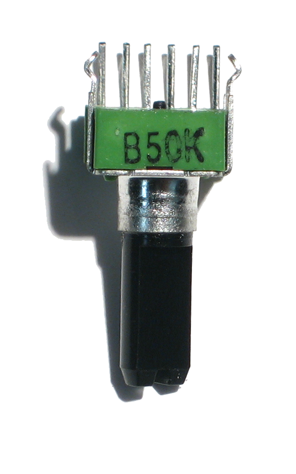
x0xb0x dual lin pot part @50k
http://www.ladyada.net/images/parts/50K-B.jpg
BTW pots turn at 270°, encoders are endless
-
-64+64 : ableton va automatiquement mapper ton potard et le CC et la valeur 63 sera reconnu comme 0dB. pour info les CC midi vont de 0 à 127, le fait de marquer -64 est une interprétation du midi pour coller à la représentation humaine de la chose, en fait c'est 0)
pour utiliser la meme surface de controle sur chaque tranche de console, il suffit de faire plusieurs mémoires dans ta MB64, les assignations de control change étant différentes entre mémoires
(ex :
tranche Bassdrum -> réglage de compression sur le CC24 canal midi 1,
tranche Snare -> ce même potard de compression sur CC24 mais canal midi 2)
et bien entendu mémoire1 = tranche1, mémoire 2= tranche2, etc
il existe un editeur de mb64 dans mios studio pour faire ça "plus" vite qu'avec le petit écran LCD (et donc ça te dispense de l'écran LCD ^^)
par ailleurs je te conseille plutot des potentiometres que des encodeurs car l'index te permettra de savoir ta position sans avoir à regarder un écran annexe, ni des LED, sans parler du toucher qui est un million de fois plus sympa ; y a une case à cocher dans un des menus pour que le mouvement du potard ne soit effectif que lorsque tu repasses par la position "d'origine".
dans ce cas, pas besoin de passer par les circuits tout fait : tu achètes de la plaque pastillée et tu fais toi meme les pistes des circuits avec de la soudure. t'as juste besoin d'un PIC ! (je peux meme t'en filer un) et des analog multiplexeur (ça coute 0,5€ le composant et tu peux en mettre 4 pour 64 potards !)
par ailleurs il existe une version mackie control/logic control de la midi box. Ã creuser
je possède une mackie control et son C4 sur Logic et franchement, le fait que Logic gère automatiquement ces surfaces est un pur plaisir. dommage qu'ableton ne gère pas le C4.
-
-
Doug, please, give us some news.
No update on your site since december..
Have you received PCB's? what is the status of this very long project?
+1
-
spare ETH and SD card PCB
flip, If no one answer, I advise you to look at eBay, there are cheap ready-to-go products, search for "arduino ethernet" & "arduino SD Card" :thumbsup:
-
contacte moi par message perso
un ancien de Louis Lumière ;)
-
IIC MIDI Module
yep. very good idea. aIalso though to very minimalistic schem on vero board : pics and crystals only. supply , octocoupler taken directly on the juno, the whole stuff being inside the Juno 106.
my project is on standby as i am currently focusing on OSC, Midi and Arduino. The idea is to use the iPad as a CS.
-
Elektron Monomachine ?
-
there are 2 rows so that you can chain DOUT and DIN (notice So Si), a single DIN or DOUT being connected to the Core
LED's on MIDI in/out on the CORE32
in MIDIbox SEQ
Posted
you have to do something similar to the GM5X5X5 board designed by nILS, using 74HCxx chip. this is NOT included in the Core32 PCB.
another trick is to put a LED in the current loop of the MIDI connector :
http://ogloton.free.fr/realisations_minutes/test_midi.html