

jrp
-
Posts
225 -
Joined
-
Last visited
-
Days Won
1
Content Type
Profiles
Forums
Blogs
Gallery
Everything posted by jrp
-
 The way i am using this my functions are actually all in a list called MIOS_SYSEX_COMMAND_FUNCTIONS[ID] so in this example : MIOS_SYSEX_COMMAND_FUNCTIONS = { MyFunction = function(numbers) print(numbers[1] .. numbers[2]) end, }
 -
if you place this in your root script in TouchOSC, the text element will display the last messages from MIOS32. I included a little parser that can be used to trigger functions and transmit data - like "Start MyFunction 4 35 2334 4 End" that will call MyFunction({4,35,2334,4})
-
-- Display MIOS32_MIDI_SendDebugMessage() messages and transmit data/trigger functions -- this prints to the Touchosc Log window, as well as to a text element called "text" local MIOS_MSG = root.children.text -- <- this text element must be in root, or simply change this adress function log(msg) print(msg) text = msg.. "\n" .. text --text = text .. "\n" .. msg local count = 0 MIOS_msg_lines = {} for line in text:gmatch("([^\n]*)\n?") do if line == "" then break end table.insert(MIOS_msg_lines, line) count = count + 1 if count >= maxLines then break end end text = table.concat(MIOS_msg_lines, "\n") MIOS_MSG.values.text = text end -- messages in the form of "Start .. ID .. list of numbers seperated by spaces .. End" can be used to transmit data to TouchOSC and call functions local MIOS_SYSEX_COMMAND_FUNCTIONS = { -- numbers from mios are 0 based! MyFunction = function(numbers) print(#numbers) end } function Do_MIOS_Sysex_Command(ID, numbers) local fn = MIOS_SYSEX_COMMAND_FUNCTIONS[ID] if fn then fn(numbers) end end -- sysex message handling local sysex_buffer = {} local last_sysex_time = 0 local sysex_timeout = 200 -- ms (adjust if needed) function flush_sysex_buffer() if #sysex_buffer > 0 then local msg = table.concat(sysex_buffer) sysex_buffer = {} log("MIOS32 (timeout flush): " .. msg) Log("[TIMEOUT] " .. msg) end end function onReceiveMIDI(sysExMessage) local now = os.clock() * 1000 -- ms resolution -- if too much time passed since last byte -> flush old buffer if now - last_sysex_time > sysex_timeout then flush_sysex_buffer() end last_sysex_time = now local headerLen = 8 for i = headerLen + 1, #sysExMessage do local b = sysExMessage[i] if b == 0xF7 then -- end of SysEx, flush buffer as a complete message local msg = table.concat(sysex_buffer) sysex_buffer = {} local ID = msg:match("^Start%s+(%a+).-%d+.-End$") if ID then local numbers = {} for num in msg:gmatch("(%d+)") do table.insert(numbers, tonumber(num)) end Do_MIOS_Sysex_Command(ID, numbers) else log("MIOS32: " .. msg) end else if b ~= 0 then table.insert(sysex_buffer, string.char(b)) end end end end
-
I have a function that does some heavy floating point math (calibrating solenoids to a nice midi velocity response). It works, but is slow. The STM32 does seem to have an FPU. Is it enabled in MIOS32? If not, how can i enable it in my application and make the compiler use it? Thanks!
-
scan all inputs once after start of mios 32, send out via midi
jrp replied to ranger930's topic in MIOS programming (C)
i jst saw that tk answered the same question regarding mios8. The same should apply here. It works alsmost like the code i suggested above, with one big difference: I was suggesting a global variable. That does work, but is usually a good idea to avoid. The neat thing i just learned, and since we are both learning i like to share this:: What is a static variable? It is a variable that will be created once and not change over function calls. So if the code below would read "unsigned char ain_sent = 0;" without the static keyword, the variable would be recreated every tick and midi would be sent every ms. With static, this variable will be created once inside the function block (so it is not polluting the global namespace). Next time it will be 1 and the condition in the if statement will fail. ///////////////////////////////////////////////////////////////////////////// // This function is called by MIOS in the mainloop when nothing else is to do ///////////////////////////////////////////////////////////////////////////// void Tick(void) __wparam { static unsigned char ain_sent = 0; if( ain_sent == 0 ) { unsigned char pin; unsigned char num_ain = MIOS_AIN_NumberGet(); ain_sent = 1; // only sent once after startup for(pin=0; pin < num_ain; ++pin) { MIOS_MIDI_TxBufferPut(0xb0); // CC at channel 1 MIOS_MIDI_TxBufferPut(pin); // pin number corresponds to CC number MIOS_MIDI_TxBufferPut(MIOS_AIN_Pin7bitGet(pin)); } } } -
scan all inputs once after start of mios 32, send out via midi
jrp replied to ranger930's topic in MIOS programming (C)
it´s in the manual under din http://midibox.org/mios32/manual/ I cannot try this right now, but i would assume something like int my_button = MIOS32_DIN-PinGet(0); will save 1 or 0 to the variable my_button. But again, if you have a normal "digital" push button this will only work while the button is actually pressed. -
scan all inputs once after start of mios 32, send out via midi
jrp replied to ranger930's topic in MIOS programming (C)
s32 MIOS32_DIN_PinGet (u32 pin) With this function you gen poll the state of a din pin, eg when using switches in your setup. -
scan all inputs once after start of mios 32, send out via midi
jrp replied to ranger930's topic in MIOS programming (C)
The thing is: With all digital inputs you cannot get any state UNLESS a button is pressed. It would be different with actual switches that hold their state low or high. But a button or encoder has no permanent state. When you press or turn it you get a pulse that will trigger the mios callback routine. Thats it. So the direction you should be looking is to save the last state of all buttons and encoders in your code, and load it on startup. Unfortunately i am still a noob, so i cannot really tell you how to do that. But there is some example code for sd cards and bancsticks. -
scan all inputs once after start of mios 32, send out via midi
jrp replied to ranger930's topic in MIOS programming (C)
i am also wondering about running a function once. I was under the impression that this could be done within the init function, but that does not seem to work. What does work (please tell us if this is not the way to do this) is defining a variable like: u8 has_run = 0; then in the background task you can check for has run == 0, do your stuff, set has_run to something different than 0. Your code inside the if statement will never run again... if (has_run==0){ do everything you want; has_run = 1; } -
Dear Forum, like the titel suggests. The TLC5947 can be bought in ready soldered modules and was suggested to me for dynamically driving solenoids, as an alternative to dac channels i proposed in my other thread. Reason is the parts count, so before i build 24 ladders with analog shaping and drivers i thought i should maybe look into pwm once more. So the question is if from within an mios32 application, i can use the SPI interface. If so i would try to code some form of "hello world" example with the pwm module first and then go from there. Also is it fast enough? I need a pulse of less than 5ms to minimize the on time of the solenoids and give good response with pecussive instruments. Has anyone done something similar? Thanks!
-
pyBLM - Headless Python-based Novation Launchpad BLM implementation [BETA]
jrp replied to borfo's topic in MIDIbox BLM
i think it´s super cool that you post this after three years - we all know how fast a project can be on halt and never be returned to... I woul love to try this! Go midibox 2025! -
If anyone is interested, this sort of works, turning off the pins/updating the lcd after a specified time. It works as in the J5 debounce tutorial 006_rtos_task. Thanks for all the great tutorials, they really provide a good starting point for people like me!
-
// $Id$ /* * MIOS32 Tutorial #020: LCD Output * see README.txt for details * * ========================================================================== * * Copyright (C) 2009 Thorsten Klose (tk@midibox.org) * Licensed for personal non-commercial use only. * All other rights reserved. * * ========================================================================== */ ///////////////////////////////////////////////////////////////////////////// // Include files ///////////////////////////////////////////////////////////////////////////// #include <mios32.h> #include "app.h" #include <stdbool.h> const char* bool_to_string(bool value) { return value ? "1" : "0"; //u8 velocity_dependent_timings[16]={20,18,17,16,14,13,10,10,10,10,10,10,10,10,10,10}; } u8 note_off_timers[24]; ///////////////////////////////////////////////////////////////////////////// // This hook is called after startup to initialize the application ///////////////////////////////////////////////////////////////////////////// void APP_Init(void) { // initialize all LEDs MIOS32_BOARD_LED_Init(0xffffffff); // initialize all pins of J5A, J5B and J5C as outputs in Push-Pull Mode int pin; for(pin=0; pin<12; ++pin) MIOS32_BOARD_J5_PinInit(pin, MIOS32_BOARD_PIN_MODE_OUTPUT_PP); int i; for(i=0; i<24; ++i) { note_off_timers[i]=0; } } ///////////////////////////////////////////////////////////////////////////// // This task is running endless in background ///////////////////////////////////////////////////////////////////////////// void APP_Background(void) { // clear LCD // MIOS32_LCD_Clear(); } ///////////////////////////////////////////////////////////////////////////// // This hook is called each mS from the main task which also handles DIN, ENC // and AIN events. You could add more jobs here, but they shouldn't consume // more than 300 uS to ensure the responsiveness of buttons, encoders, pots. // Alternatively you could create a dedicated task for application specific // jobs as explained in $MIOS32_PATH/apps/tutorials/006_rtos_tasks ///////////////////////////////////////////////////////////////////////////// void APP_Tick(void) { // PWM modulate the status LED (this is a sign of life) u32 timestamp = MIOS32_TIMESTAMP_Get(); MIOS32_BOARD_LED_Set(1, (timestamp % 20) <= ((timestamp / 100) % 10)); int i; for(i=0; i<24; ++i) { if( note_off_timers[i]>0) { --note_off_timers[i]; } else { int j = i*4; MIOS32_BOARD_J5_PinSet(j, 0); MIOS32_BOARD_J5_PinSet(j+1,0); MIOS32_BOARD_J5_PinSet(j+2,0); MIOS32_BOARD_J5_PinSet(j+3,0); MIOS32_LCD_CursorSet(j, 0); // X, Y MIOS32_LCD_PrintString(" "); } } } ///////////////////////////////////////////////////////////////////////////// // This hook is called each mS from the MIDI task which checks for incoming // MIDI events. You could add more MIDI related jobs here, but they shouldn't // consume more than 300 uS to ensure the responsiveness of incoming MIDI. ///////////////////////////////////////////////////////////////////////////// void APP_MIDI_Tick(void) { } u8 start=0; // to clear the lcd... int velocity_4bit; ///////////////////////////////////////////////////////////////////////////// // This hook is called when a MIDI package has been received ///////////////////////////////////////////////////////////////////////////// void APP_MIDI_NotifyPackage(mios32_midi_port_t port, mios32_midi_package_t midi_package) { // toggle Status LED on each incoming MIDI package MIOS32_BOARD_LED_Set(0x0001, ~MIOS32_BOARD_LED_Get()); // no idea how and where else i can clear the lcd if( start == 0 ) { MIOS32_LCD_Clear(); start=1; } if( midi_package.type == NoteOn && midi_package.velocity > 0 ) { u8 note_number = (midi_package.note % 12); u8 dout_pin = note_number * 4; velocity_4bit = midi_package.velocity >> 3; //note_off_timers[note_number] = velocity_dependant_timings[velocity_4bit]; MIOS32_BOARD_J5_PinSet(dout_pin, !((velocity_4bit >> 3)) & 1); MIOS32_BOARD_J5_PinSet(dout_pin+1, !((velocity_4bit >> 2)) & 1); MIOS32_BOARD_J5_PinSet(dout_pin+2, !((velocity_4bit >> 1)) & 1); MIOS32_BOARD_J5_PinSet(dout_pin+3, !((velocity_4bit >> 0)) & 1); // Just for testing: Print to lcd: MIOS32_LCD_CursorSet(dout_pin, 0); // X, Y MIOS32_LCD_PrintString(bool_to_string((velocity_4bit >> 3) & 1)); MIOS32_LCD_CursorSet(dout_pin+1, 0); // X, Y MIOS32_LCD_PrintString(bool_to_string((velocity_4bit >> 2) & 1)); MIOS32_LCD_CursorSet(dout_pin+2, 0); // X, Y MIOS32_LCD_PrintString(bool_to_string((velocity_4bit >> 1) & 1)); MIOS32_LCD_CursorSet(dout_pin+3, 0); // X, Y MIOS32_LCD_PrintString(bool_to_string((velocity_4bit >> 0) & 1)); note_off_timers[note_number] = 3000/(velocity_4bit*2); // just for testing, this has to be tested and maybe we want longer gate for low velocity MIOS32_LCD_CursorSet(0, 1); MIOS32_LCD_PrintFormattedString("%02d:%02d:%02d", midi_package.velocity,velocity_4bit,note_off_timers[note_number]); } else if( (midi_package.type == NoteOff) || (midi_package.type == NoteOn && midi_package.velocity == 0) ) { u8 dout_pin = (midi_package.note % 12)*4; MIOS32_BOARD_J5_PinSet(dout_pin, 0); MIOS32_BOARD_J5_PinSet(dout_pin+1,0); MIOS32_BOARD_J5_PinSet(dout_pin+2,0); MIOS32_BOARD_J5_PinSet(dout_pin+3,0); //MIOS32_LCD_CursorSet(dout_pin, 0); // X, Y //MIOS32_LCD_PrintString(" "); } } ///////////////////////////////////////////////////////////////////////////// // This hook is called before the shift register chain is scanned ///////////////////////////////////////////////////////////////////////////// void APP_SRIO_ServicePrepare(void) { } ///////////////////////////////////////////////////////////////////////////// // This hook is called after the shift register chain has been scanned ///////////////////////////////////////////////////////////////////////////// void APP_SRIO_ServiceFinish(void) { } ///////////////////////////////////////////////////////////////////////////// // This hook is called when a button has been toggled // pin_value is 1 when button released, and 0 when button pressed ///////////////////////////////////////////////////////////////////////////// void APP_DIN_NotifyToggle(u32 pin, u32 pin_value) { } ///////////////////////////////////////////////////////////////////////////// // This hook is called when an encoder has been moved // incrementer is positive when encoder has been turned clockwise, else // it is negative ///////////////////////////////////////////////////////////////////////////// void APP_ENC_NotifyChange(u32 encoder, s32 incrementer) { } ///////////////////////////////////////////////////////////////////////////// // This hook is called when a pot has been moved ///////////////////////////////////////////////////////////////////////////// void APP_AIN_NotifyChange(u32 pin, u32 pin_value) { }
-
///////////////////////////////////////////////////////////////////////////// // Include files ///////////////////////////////////////////////////////////////////////////// #include <mios32.h> #include "app.h" #include <stdbool.h> const char* bool_to_string(bool value) { return value ? "1" : "0"; }
-
now i have to look into timers to get some way of resetting my pins after some ms. Solenoids don´t like to be "on" for long, and the glockenspiel needs only a short percussive hit.
-
that was easier to code than i thought. I really enjoyed learning about this. I dont have my scope, my douts or any leds here, so i added some code to print the output pattern to the lcd. I noticed that if i put the clear_lcd command outside any of the function blocks, i get an error during compilation. No sure how this should be done. I found a workaround though... #include <stdbool.h> is needed at the top of main.c for the display of the boolean values on the lcd u8 start=0; // to clear the lcd... int velocity_4bit; ///////////////////////////////////////////////////////////////////////////// // This hook is called when a MIDI package has been received ///////////////////////////////////////////////////////////////////////////// void APP_MIDI_NotifyPackage(mios32_midi_port_t port, mios32_midi_package_t midi_package) { // toggle Status LED on each incoming MIDI package MIOS32_BOARD_LED_Set(0x0001, ~MIOS32_BOARD_LED_Get()); // no idea how and where else i can clear the lcd if( start == 0 ) { MIOS32_LCD_Clear(); start=1; } if( midi_package.type == NoteOn && midi_package.velocity > 0 ) { u8 dout_pin = (midi_package.note % 12)*4; velocity_4bit = midi_package.velocity >> 3; MIOS32_BOARD_J5_PinSet(dout_pin, !((velocity_4bit >> 3)) & 1); MIOS32_BOARD_J5_PinSet(dout_pin+1, !((velocity_4bit >> 2)) & 1); MIOS32_BOARD_J5_PinSet(dout_pin+2, !((velocity_4bit >> 1)) & 1); MIOS32_BOARD_J5_PinSet(dout_pin+3, !((velocity_4bit >> 0)) & 1); // Just for testing: Print to lcd: MIOS32_LCD_CursorSet(dout_pin, 0); // X, Y MIOS32_LCD_PrintString(bool_to_string((velocity_4bit >> 3) & 1)); MIOS32_LCD_CursorSet(dout_pin+1, 0); // X, Y MIOS32_LCD_PrintString(bool_to_string((velocity_4bit >> 2) & 1)); MIOS32_LCD_CursorSet(dout_pin+2, 0); // X, Y MIOS32_LCD_PrintString(bool_to_string((velocity_4bit >> 1) & 1)); MIOS32_LCD_CursorSet(dout_pin+3, 0); // X, Y MIOS32_LCD_PrintString(bool_to_string((velocity_4bit >> 0) & 1)); MIOS32_LCD_CursorSet(0, 1); MIOS32_LCD_PrintFormattedString("%02d:%02d", midi_package.velocity,velocity_4bit); } else if( (midi_package.type == NoteOff) || (midi_package.type == NoteOn && midi_package.velocity == 0) ) { u8 dout_pin = (midi_package.note % 12)*4; MIOS32_BOARD_J5_PinSet(dout_pin, 0); MIOS32_BOARD_J5_PinSet(dout_pin+1,0); MIOS32_BOARD_J5_PinSet(dout_pin+2,0); MIOS32_BOARD_J5_PinSet(dout_pin+3,0); //MIOS32_LCD_CursorSet(dout_pin, 0); // X, Y //MIOS32_LCD_PrintString(" "); } }
-
i looked through the analog toolbox code, there it appears that a timer is set to produce a tick every 1ms. So i will try to got that route in mios32.
-
This looks amazing! With some of the older chips like vintage vca, filter or delay chips you really have to be careful regarding heat and also (or even more so) static discharge. Nowadays with most ics these issues have long been solved by modern manufacturing processes and built in safety measures. I had to lear the hard way that this is not the case with chips from the 80s... So the heatsink is probably a good idea, as would be any way to allow for some airflow. On the other hand, i have removed the fans from some of my gear with no issues at all, as commercial units have to consider every worst case scenario (crowded rack in hot environment). So if you know how you use your gear you can get away with things that could not be allowed for every scenario.
-
Thanks! Since i need two octaves the resistor ladder cv-lc will not get me far. Using three Midibox_CV_NG would do the trick, but i consider this really overkill since i am pretty sure that i will not get more than 8, maybe 16 different amplitude levels with the solenoids and Glockenspiel. So 3 or 4 bit resolution should be ideal. I have since been looking once more into the dout example in the mios32 programming section. The code to adress 4 dout pins for every note to get 16 voltage levels should be very straight forward. I am sure to get something running over the weekend. I will see if there are any general design problems with this idea.
-
Dear forum, i would love to designa midibox that gives me up to 32 custom velocity sensitive envelopes with some special shapes (i want two attack phases) That makes me think: How do you program the timing of an envelope? I would love to learn about this :) In Mios32 there are timers, ticks, delay, freeRTOS tasks.... Where would you built an simple envelope generator? The finished apps like midiboxCV2 are so complex that i could not really find the answer in the code myself. Btw, midiboxCV2 would fit my usecase perfectly, but it is limited to one AOUT module. Thank you very much!
-
i have not tried this, but from what i understand most parameters of the sid are controllable from cc or sysex. MidiboxNG could be used to enhance the midibox Sid control suface. Or maybe(!) MidiboxNG could function as a complete programmer for the MB_SID, also handling saving of patches. Not sure though, if i remember correctly not all parameters are available as sysex... If you have any findings please let us know, i am also interested in this. A midibox Sid with an extended control suface, led-rings, maybe with motorfaders, oled displays, BL-Matrix....
-
Dear Forum, to drive electro magnetic actuators with some velocity sensitivity i am thinking about -instead of using 4 expensive Aout modules with the need of bipolar power: - mapping midi note on and velocity to 3 or 4 dio pins with a resistor ladder to get 8 or 16 voltage levels. I would tune the resistors to get a custom curve because solenoids need a minimum impulse to get moving (initial lowest level around 50%, then linear to 100% from there). Is this a reasonable idea? What Midibox App is a good starting point? Can this be done with MidiboxNG? From reading through the Manual i assume yes, but is it reasonable and fast enough for 24 3 or 4 bit outs? (Midifying a 2 octave Glockenspiel) Or should i start from scratch with a new mios32 app? I know a little C and i have worked through most of the tutorials.... but not much more. The documentation is superb, but still i feel a little lost... My solution is sure to have a lot of if statements, propably hard coding every velocity of every note value by hand... Or is it necessary to program a driver for a new "Midibox Aout_4Bit" module? (<- would be the thing i feel least confident about, no idea where to start...) As an alternative i tried using the pwm signal from dimmed LEDs in MidiboxNG, but that did not work very well bacause the pwm frequency is rather low (around 4 pulses in 10ms), to slow for very short trigger impulses. I am really excited to getting started with 32 bit Midibox - my last build was the MB Sid, quite some years ago :) Thanks for any comments!
-
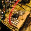
Thank you! Didn´t think of mouser! Even on Amazon they are only listed as smd. My next step would have been to solder them using little wires on every second pin... like with the mb-cv dac on my avatar photo. At Reichelt it can be found as 74HC 541 in dip, but i assume this will not work with the logic level coming from the controller. 75HCT541 is only available as SO20.
-
I have the same problem... where has it been answered?
-
No USB-Midi: Is this the correct bootloader blinking?
jrp replied to jrp's topic in Testing/Troubleshooting
Hi Thorsten, thanks so much! I tried everything suggested in that other thread, with no result. Then i managed to get my hands on a few more micro-usb cables. Guess what, i had been switching between two faulty cables. Everything is running fine now, core is detected in Mios-Studio. PS.: I am happy to be back with this stuff :) Back at ucapps.de Didn´t find the time for a long while. Now i got a job at the HfM Nürnberg to (among other stuff) build robotic percussion... If all goes to plan they will be powered by midibox :)
