

jrp
-
Posts
225 -
Joined
-
Last visited
-
Days Won
1
Content Type
Profiles
Forums
Blogs
Gallery
Everything posted by jrp
-
from the cc implemention chart (sid manual): The CC implementation covers the most important parameters at 7bit resolution, so that they can be easily accessed from a DAW or a common MIDI controller. CC changes are non-destructive and won't affect the edit buffer. This isn't a bug, but a feature! Means: your edits on the Control Surface won't be overwritten by incoming CCs, but as an effect they won't be displayed on the LCD, and you won't be able to store changes made via CC as a new patch. I still have a lot of old pics here, so if anyone has a hint how to make it send NRPN on pot movement that would be great! In 8bit programming section there is an example for sending cc on pot movement (first example in the list). It is propably necessary to make it look what sid is currently active (simply by looking at the dout pins driving the sid 1-4 LEDs), so that data can be sent to each connected core. Not sure how this has to be implemented. Propably hard if different ensambles with different midi channel mapping will be used... In this case it´s propably best to have the controll pic handle midi mapping and use just a single ensamble on the master sid. What i am thinking of is a box that will controll around 10 to 16 parameters from analog pots in full resolution. I was nevery happy with the feel of encoders for tweaking the synth. I am a studio user, so i wouldn´t mind the parameter jumps. And there is still the option to use encoders alongside.
-
i found this in the documention somewhere: CC will not alter the edit buffer or something like that. I think it will work if you are in edit mode? Can´t find where i read this right now. Or you have to use sysex ot Nrpn. I am interested in the same as i wish to add a lot of analog pots to my sid (for envelopes and filter, maybe also some lfos). I guess this can be done with MB_NG, i think MB_64e can only send cc (?).
-
All can be done, it depends on your needs. My sid has independant outs with stereo volume controll on each voice. Voices 2 to 4 have a little switch that mixes them with voice 1. I used a simple inverting opamp mixer as can be found using google.
-
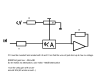
in fact the osc-envelopes are independant from the main volume that is forwardet to aout. So yes and no. If you activate GSA the oscs will always be "on", playing at their sustain value. So in fact if A=0 D=0 you can set the osc-volume with S=1 to 15. It is also possible to use without GSA, then you should just adjust the release so that the osc wont be turned off before your vca modulation has fadet out the note. I built my ssm vca on veroboard and never bothered to draw a detailed schematic. I would recoment having a look into the datasheet, in the meentime i try a little drawing... I am working on a complete analog channel with some effects right now, but that´ll take some time... The schematic you linked will work, but it´s more than you need. Since the cv(aout) can be inverted in the ensamble you only need a trimmer to scale it down when driving the vca directly. Note that complete Aout module is not needed. I drive mine directly with the DAC connected to the core. i attached a little drawing.
-
Using a vca is a very good idea! You want a log responce VCA in combination with the MB_SIDs envelopes. All of the VCAs i tried required a small cap on the cv line to tame the initial click. I tried this LM13700 design http://www.musicfromouterspace.com/analogsynth_new/DUALVCA/DLLVCA001.html Note that both sides should be log! Several versions of these on the net. It sounds good and gives a nice decay! SSM2164 is also an very good candidate. I settled on using these as there are 4 vcas in a chip, easy to use. If you invert the aout-channel in the ensamble menu just a trimmer is needed to interface to this vca. Also good sounding. The VCA included in my CEM3379 filters was not working that nice due to it´s uncommon cv responce. From 0-200mv it´s log - crowding the whole range of -100db to -20db into this little cv. the ramaining 20db get controlled linear with cv from 200mv to 5v. The effect of this: it sounds less dynamic. Decay and release is much longer and somehow squashed. Still it´s useful for some other tasks around my sid(...)...
-
do you know if lcd displays in larger physical sizes are available anywhere? All the displays i can find share the same standard layout. First reason: I have bad eyes Second reason: I would like to fit 10 encoders under a 40*2 lcd. thanks!
-
could somebody confirm this works? In my case it did nothing :(
-
The title says it all... I´m back designing my take on the midibox sid and i just noticed that lcds with 40*4 are available, . Would be nice to have 10 parameters on screen and the parameter bar and title from the 20*4 configuration (even if the bar only fills half the display). Can MIOS handle it and ill the sid application do it by setting #define CS_MENU_DISPLAYED_ITEMS 10 #define DEFAULT_LCD_LINES 4 ? Thank you very much!
-
Thanks for your thoughts! The resonance on the cem works really good, the level stays very solid. Good for the sound but also for a couple of other things. I tried FM and AM (sid output pre VCF applied to the CV ins). Gives you some very interesting sounds, especially with higher resonance settings. For Highpass operation (LP-dry signal=HP) the small gain variation from increased resonace can be easily compensated with one side of the paning VCA. Relly useful chip, a shame they are dicontinued. Days of the analog dinosours are gone... Rather on the clean side soundwise i would say. Like the big polysynths it was invented for maybe. I think with a selfmade VCF a lot more mojo can be had. Build a moog once and started a steiner. The moog is definitly a beast compared to the cem. The Polivoks VCF i never build, but i looked at the schematic a couple of times. You know this page? Good info on the Polivoks. http://modularsynthesis.com/kuzmin/polivoks/polivoks_vcf.htm
-
Hello, just wondering, how does the SSM filter differ soundwise from the CEM chip? The CEM has extra building blocks that are useful and i like it´s sound. Haven´t heard a SSM, but i could imagine they are similar?
-
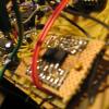
i can see that, absolutley! You have created a pice of art here and i wouldn´t expect for anything. I spend every free minute for the last three weeks building and playing with my sid and i absolutley love it. It´s in a cardboard box and has wires all over and i am testing analog effects and filters to go along with it. I expect to finish it not very soon, so who knows, maybe i´ll learn some asembler :) I was just hoping there might be an easy way to have those 4 bits printed out a dout shiftregister.
-
Hello, Propably this idea is just too complex to implement, but i´ll ask anyhow... Sorry, can´t help it. MBSid is a fascination and i think about it all the time... Any chance to output CS_MENU_GetScaledParam through the dout chain in any form? I am designing my own cs with some dedicated extra encoders i managed to implement (for Aout, envelopes, 8 menu encoders). I am using a 40*2 display. I really like the menu structure, but for editing a synth with many knobs it is nice if you don´t have to look at the display. Also it would be possible to adjust menu order and cursor offset so that, for example, if you tweak the envelope encoders the display will flip to the env screen but show different parameters than those assigned to the env encoders, ready to be tweaked as well with the menu encoders. For this some kind of visual feedback of the tweaked parameter would be great. The 20*4 display option shows a bargraph on the lower line. I looked at the code in the cs_menu.inc and i see there are quite a few steps going on to get a value and print it. Do you see any chance to output this value in any form over the dout chain? Driving a BCD display or a LED bar comes to mind (many pins). If i undestand the basics a BCD value can be transformed to a analog voltage with a resistor ladder. So even a LM3914 driven LED bar would be an option. I certainly wouldn´t mind the extra soldering.
-
I thought so (after writing my post). I also had a look at the datasheet of the sid, explains it as well. Well, would have been nice, but on the other hand having envelopes for each voice is great as it is. And limitations can be worked around. If i want the effect of a single voice fading in that can be done with long attack times. Especially in the studio when you can tweak the patch to match the notelength of a part. It interests me how you programmers are working. Am i on the right track that (if it were possible) you would make your code do something like this? max attack level = 0F or: max attack level = sustain level I only toyed a little bit with some of your code and i am really fascinated how these things work together. Only logic (and smart use of it) makes things happen. Not that i know any more about code than a little GW-Basic from when i was a child. Still logic can be very comforting...
-
One of the greatest features i overlooked at first is the envelope each oscilator has. For static operation i set Atck and Dec to 0 and control volume with Sustain to balance the sound. With Attack it is possible to fade in each individual oscilator. Very cool! The osc will fade in to maximum level and then decay to sustain. Also very cool effects! But often i would find it very useful if the osc could fade in to sustain-level without rising to maximum amplitude first. So that the voice would fade in softly to a defined level and blend in with the others. Like you have a Triangle wave and want to fade in just a bit of saw. With the ADSR function it will go "WHEII" first and then settle. Very nice with arpegiators... I definitly like having both options! In the analog world of an envelope generator i can flip one resistor on an comparator. Then it compares the charging of the capacitor with the sustain voltage instead of a (max level) reference and stops the charging as soon as sustain is reached. I call that ASR In the ADSR the comparator will let the cap charge to that max level and then release it to discharge down to sustain. Attack and Decay (and Release) are simple variable resistors, acting as a bottleneck for the current, making the charging and discharging take some time. I wonder, in code, will this be much more complicated than that? Simply wiring in a switch to change a constant for a variable max attack level = 0F or: max attack level = sustain level Or is this simply impossible because the osc-envelopes are inside the sid and not generated by the software?
-
Added some encoders to dial through waveforms etc. only works with env-layer
jrp replied to jrp's topic in MIDIbox SID
when i place everything on the end of the list, not inbetween LFO and Filter, it works with ENV-Ctrl set to assign. While in the env layer it doesn´t. I could actually live with that, assign layer is great and if i tap on the env_select button i got my Depth, A D2 S R as the first 5 items on the screen anyhow. Being a code noob i would propably replace the env_ctrl button with an rc network to set the pin high just after loading. It will set Ctrl to Assign after power on. But hey, maybe i could learn how to add some controlls the way it´s supposed to be done. Without messing stuff up... -
i got it all by myself :) thanks to the perfectly organiced code i was able to discover that the env encoders are linked to a menu position in the file cs_menu_enc_table.inc I changed the cursor and page offset. ;; Env "Env" Layer ;; menu offset cursor pos ;; CSENC_ENTRY CS_MENU_L_ENV, 0x01, 0x01 ; Depth ;; CSENC_ENTRY CS_MENU_L_ENV, 0x02, 0x03 ; Attack ;; CSENC_ENTRY CS_MENU_L_ENV, 0x06, 0x08 ; Decay ;; CSENC_ENTRY CS_MENU_L_ENV, 0x09, 0x09 ; Sustain ;; CSENC_ENTRY CS_MENU_L_ENV, 0x09, 0x0a ; Release CSENC_ENTRY CS_MENU_L_ENV, 0x00, 0x00 ; Depth CSENC_ENTRY CS_MENU_L_ENV, 0x00, 0x01 ; Attack CSENC_ENTRY CS_MENU_L_ENV, 0x00, 0x02 ; Decay CSENC_ENTRY CS_MENU_L_ENV, 0x00, 0x03 ; Sustain CSENC_ENTRY CS_MENU_L_ENV, 0x00, 0x04 ; Release After that, all was fine, but now my Env select button wasn´t working anymore. Aha - it must be pointing to position 0 of the menu where the parameter used to be.... In menu_buttons.inc i found the right lines of code CS_MENU_BUTTON_Env_Sel_L ;; increment ENV setting movlw 0x05 ; cursor pos movwf MIOS_PARAMETER1 movlw 0x00 ; page offset movwf MIOS_PARAMETER2 call CS_MENU_GetMenuID_ENV ; menu page goto CS_MENU_ButtonInc ;; movlw 0x00 ; cursor pos ;; movlw 0x00 ; page offset ;; movwf MIOS_PARAMETER2 ;; call CS_MENU_GetMenuID_ENV ; menu page ;; goto CS_MENU_ButtonInc ;; ;; now it´s fine! I´ll try to get into this some more. i could find it useful to select the envelope page with the env select button - then controll the envelope with the ecoders in assign mode (now fitting depth,a,d,s,r) -and then maybe redirecting the encoders on the env layer to do something alltogether different like controlling the depth of 5 lfos or analog outs, etc.
-
Hello, I wanted to get rid of the fact that the display will scroll left and right while editing the envelope on the cs. After doing the rearrengement in the CS_Menue_Tables.inc the lcd is now starting with Depth, Attack, Decay, Sustain, Release. But now the 5 Encoders of the envelope section control wrong parameters. Seems like they are linked to a menu position rather than a dedicated function. Is there a fix i could do? Maybe another topic: Is there any chance to make the screen return to the last menu after an encoder has been turned? When i am editing a wavetable and turn a knob on the cs the display will jump to the associated menu and stay there. Good feature. It just would be nice if one could just jump to the last menu somehow
-
I just tried this and changed btfss to btfsc. After compiling and uploading nothing changed. I edited some menu orders and other things at the same time, these changes worked, so my upload was succesfull. In cs_menu.inc i see two lines with CS_MENU_MODE, CS_MENU_MODE_SHIFT_PRESSED maybe they both need to be edited? one in this block (already edited) CS_MENU_EncSpeedSet_ModVal_GT1F ;; max value > 0x1f: set fast speed movf CS_MENU_PARAMETER_MAX_H, W movwf TMP2 rlf TMP1, F rlf TMP2, F movlw 0x05 ; saturate if value >= 5 cpfsgt TMP2, ACCESS ; (IFLEQ) movf TMP2, W ;; increase speed if shift button pressed btfsc CS_MENU_MODE, CS_MENU_MODE_SHIFT_PRESSED addlw 2 and another one a bit above in the code: CS_MENU_EncSpeedSet_Main movlw 2 ; this speed value is taken when ENC_SPEED_FAST is selected movwf MIOS_PARAMETER2 movlw MIOS_ENC_SPEED_FAST ; FAST or NORMAL mode depending on state of shift button btfsc CS_MENU_MODE, CS_MENU_MODE_SHIFT_PRESSED movlw MIOS_ENC_SPEED_NORMAL movwf MIOS_PARAMETER1 movf PRODL, W ; encoder number goto MIOS_ENC_SpeedSet
-
I edited (deleated) an old thread with no answers since i was able to answer myself and i don´t want to open too many new threads... Midibox sid has a great fascination on me. After toying with the cs for some time i have come to realize that i want to implement some changes. Already re-arranged some menues and was able to find out how to edit the CS_MENU_ENC_TABLE.inc so that the controllers will point to the right (new) menu entries. This was useful especially for renaming entries but also re-arranging the envelope to my taste. AD2SR with D1min and DLev max. Classic ADSR Then i found out that i can implement new encoders by adding lines to CS_MENU_ENC_TABLE.inc and the SETUP_6581.asm All trial and error, i never learned programming. I was very surprised that it sort of works. Really got me excited:-) I can now define a encoder to dial (up and down) through OSC select OSC Wave LFO select LFO wave Filter source (osc) Filter Type (lp,bp,etc) Like the feel better than using the buttons from the original cs (maybe also couse the cheap buttons from pollin are trash). Also i included two more encoders: Edit menue item #6 Edit AOut ch 7 (overdrive in my sid) LFO select and wave always work, the others only work if env ctrl is set to env. When set to assign layer my new additions don´t work as expected, they seem to controll all sorts of stuff then. release, menu item 2, menu item 1, resonance... If it was the other way around i could live with it, always working in ENV-Ctrl set to assign, since my env menue represents the 5 encoders anyhow... So somehow my entries are affected by the env ctrl button. I know my code is not as it should be, i was getting allerts while compiling. column 1 pointing to makro, something like that. Also the CS_MENU_ENC_TABLE.inc says in the beginning that CS_MENU_ENC.inc has to be configured as well. No idea how. Here is my code added to CS_MENU_ENC_TABLE.inc ;; LFO section ;; menu offset cursor pos CSENC_ENTRY CS_MENU_L_LFO, 0x02, 0x02 ; Rate CSENC_ENTRY CS_MENU_L_LFO, 0x02, 0x04 ; Depth ;;;;;;;___New Lines: CSENC_ENTRY CS_MENU_L_LFO, 0x00, 0x00 ; lfo select CSENC_ENTRY CS_MENU_L_LFO, 0x00, 0x01 ; wave CSENC_ENTRY CS_MENU_L_OSC, 0x00, 0x01 ; osc wave CSENC_ENTRY CS_MENU_L_OSC, 0x00, 0x00 ; osc select CSENC_ENTRY CS_MENU_L_FIL, 0x00, 0x01 ; osc-filter select CSENC_ENTRY CS_MENU_L_FIL, 0x00, 0x04 ; filter type CSENC_ENTRY 0xff, 0x05, 0x00 ; Menu item #6 CSENC_ENTRY CS_MENU_L_EXT, 0x00, 0x06 ; aout7 My entries in the setup.asm: ENC_ENTRY 6, 6, MIOS_ENC_MODE_DETENTED3 ; LFO rate 2,6 ENC_ENTRY 6, 4, MIOS_ENC_MODE_DETENTED3 ; LFO depth 1,4 ENC_ENTRY 5, 6, MIOS_ENC_MODE_DETENTED3 ; LFO select ENC_ENTRY 5, 4, MIOS_ENC_MODE_DETENTED3 ; LFO wave ENC_ENTRY 2, 6, MIOS_ENC_MODE_DETENTED3 ; osc wave ENC_ENTRY 1, 4, MIOS_ENC_MODE_DETENTED3 ; osc select ENC_ENTRY 3, 6, MIOS_ENC_MODE_DETENTED3 ; osd-filter select ENC_ENTRY 3, 4, MIOS_ENC_MODE_DETENTED3 ; filter type ENC_ENTRY 5, 2, MIOS_ENC_MODE_DETENTED3 ; menu 6 ENC_ENTRY 5, 0, MIOS_ENC_MODE_DETENTED3 ; analog out 7 ENC_ENTRY 0, 6, MIOS_ENC_MODE_DETENTED3 ; Filter CutOff
-
That´s great! Thank you! So i activate this feature and forward "Volume" target from the mod matrix to AOut? Or will that mod target still controll the volume of the sid?
-
Ah, i see! Most have overlooked the info. And i thought i have discovered something new ;) Happy it´s running now, really great project!
-
since you already have the c64 psu (building your own is really easy) you should trace out where to take 12v (or 9v), 5v and ground from. I don´t know the c64 psu, but it propably has some connectors or points that you can easily solder on. To bring power to the gear i like to use 3 pin jacks and connectors like 3 pin din or xlr. I don´t see any nead for a pcb.
-
Sorry, no help from me on the topic, but mayby if you flip the chips back again it will continue working....electronics can be surprising/confusing sometimes
-
I just solved this strange issue by connecting a lcd (in 4 bit mode) and a pullup resistor to pin 36. That was it. Everything seems to work now. Still i find it strange that this only troubled the pic when running any of the sid applications. There were no problems with interconection test, testtone or anything else i uploaded. So if this is a new bug nobody ever saw since everyone oses a lcd from the start - then now we know :) Being confident about my build and soldering I came to the conclusion that the only difference between my cores is in the lcd connected. The core i had the thing running on already had the lcd in 8 bit mode, but since i´m happy to solder less pins i looked at the 4 bit configuration and saw the pullup on pin 36.
-
I was thinking of adding an external vca to my sid to get rid of the sound feedthrough. This is as an alternative to a noisegate and should be controlled by the amplitude modulation from the sid engine. I know this is possible, but would lead to the signal being amplitude modulated two times. First by the sid itself, then by the external vca. Would it be possible to deactivate the vca inside the sid chip? So that it will always output sound at full blast just like the vcos in an analog synth?
