

jrp
-
Posts
225 -
Joined
-
Last visited
-
Days Won
1
Content Type
Profiles
Forums
Blogs
Gallery
Everything posted by jrp
-
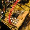
Dear Midibox-Forum, i just was trying to use a core32 for the first time. I flashed the ST-Link firmware, installed the driver and uploaded the bootloader on my STM32F4Discovery following the described methode using my win11 Laptop. Unfortunately, when i connect the micro-usb port neither my windows, nor my m2 mac computers detect any midi interface. When i look at the system-info under usb, i see the st-link, but nothing else. I tried both micro-usb cables i could find around the house. Of course they could both be faulty, i have no other device to test them with. I attached a short video of me pressing the reset button. Is this the correct light pattern on the board? In other words, is my bootloader running? Thanks, Jens IMG_2901.MOV
-
pitch, external switches and cvs sometimes not working as expected
jrp replied to jrp's topic in MIDIbox SID
anyone using all their gates at J5? -
i cannot recomend this. Linear regulators will be very unhappy in such a case. It is not that the regeulator can adapt in a mannor: "Ok, i need to drop 3V, so i just adjust myself to 8.5V." The Voltage will drop, yes, and the regulator will be fighting and sweating, not being able to do what it´s supposed to do: Stabilize voltage and get rid of any ripple. It will lead to hum and possible failure. For non demanding circuits (not this one!) it would then be better to go without a regulator altogether. Don´t try this with your sid though. Also, to be safe it is common practice to account for 10% mains variations. If you measure voltage and the regulator is a little of, just check the voltage at it´s input. These Parts have tolerances, so you might be getting 8.7V from 12v. That would be fine.
-
Any news on this? I also noticed that with some patches it can happen that the AOUT or triggers aren´t working as expected. Sume other functions as well, seems rather strange and hard to repeat. I have another thread about this, but i just saw yours. Propably it has to do with new assignments in the setup file in conjunction with older patches. Problem is i always noticed this late, so i cannot say what changes exactly made this happen. In my case Trigger 1 and 8 are not working on my slave core, on my master core i had the same problem with triggers falling back to 0. Maybe someone else besides TK can check on this or confirm it is working for them... Someone with a MB_SID using all triggers, or with an "exposed" core module so they don´t need to take stuff appart. Then at least we know it´s not a bug (what i actually doubt) but some mistake at our side (although i carefully inspected solder joints a thousand times). Thank you!
-
Am i allowed to sell stuff containing a midibox ?
jrp replied to chapelier fou's topic in Miscellaneous
Old thread but i just saw this. Beautiful work and idea! I bet the kids love this. I work at a school also, got to show this to my boss! Is it running ableton live? -
pitch, external switches and cvs sometimes not working as expected
jrp replied to jrp's topic in MIDIbox SID
Setting up a DOut shift register works for the master core, but unfortunately not on the slave module. Is this even supported? I used SR#1 for this. The three data lines coming from the pic are all low. So maybe J5 is the only way for slave cores to axcess external switches? -
pitch, external switches and cvs sometimes not working as expected
jrp replied to jrp's topic in MIDIbox SID
even stranger: on my master core Trigger 1 is high, activating the trigger on the cs flips it low for half a second. Trigger 2, 3, 4, 6 are acting the oppostite way. When turned on they fall back to low after half a second. Trigger 5, 7, 8 are functioning normal. Again, all trigger assignments in the setup.hex are turned off, J5_Function = 3 -
pitch, external switches and cvs sometimes not working as expected
jrp replied to jrp's topic in MIDIbox SID
i did a fresh install using the unmodded version downloaded from ucapps. All flags controlling external triggers were set to 0, #define DEFAULT_J5_FUNCTION 3 #define AOUT_INTERFACE_TYPE 3 #define DEFAULT_EXT_SWITCH_DOUT 0 I also disabled all shiftregister pins except for my exec button to clone this firmware to my slave core. I then reinstalled my own version setup for my hardware to the master core. It doesn´t change a thing unfortunately. Ext trig 1 is always high, 8 is always low, 2-7 are working fine. Is this a bug? Can someone confirm this is working? Propably i´ll solder in a single dout register to my slave module and try to use that one. -
I use both and think they are both great. With the 6581 (and actually the 8580 as well) an external VCA is very very nice. That way you have no more bleedthrough and you can controll the volume with the high resolution software envelope (and modmatrix). Works and sounds perfect. Oh, i like the 6581 Filter!!! But true, it is not as effective as the 8580. But it has a very nice character. My advice: Use both! Somewhere in the manual or the documentation there is an audio example comparing the two chips. Sorry, can´t find it right now.
-
pitch, external switches and cvs sometimes not working as expected
jrp posted a topic in MIDIbox SID
Hello, I wonder if anyone else has encountered strange behavior on their MB_SIDs. I belive this has to do with firmware updates as whenever something like this happenes it affects older patches. When starting with the init patch erverything seems to be working (exept for my trigger-outs 1 and 8). Symptoms: (these are all on my Core #2, Master Core seems to be working flawless) One Sid being out of tune - you have to transpose it to +50 to get into the range that should be +0. Happened only once so far. Can be solved by switching patch. One CV-Channel not working or ommiting the first half of it´s range (from 0 to 800 it outputs 0V, then output raises to 2.5v) Only CV7 is affected. Nothing is assigned in the matrix. This problem disappears when a new patch is selected. External Trigger 1 is always on, trigger 8 is always off. Nothing assigned in the setup asm, other triggers working fine. I am using J5. The external trigger 1 never worked (found no soldering issue), trigger 8 just recently stopped working. I really hope to fix this. I was doing a lot of uploads, mainly changing buttons, etc. The firmware i am using has some new buttons and encoders added, i cannot imagine that this is causing this behavior, but on the ther hand, if no one ever experiences stuff like this.... -
Did you really experiance audible distortion when AC coupling the signal? Should be very doable with a low enough Lowcut around 5Hz. Eg 330nf into a 100k load. Using a sineshaper is in fact nice as you can morph from tri to sine to square, or from saw to rounded saw to pulse. I found this sounds even more useful compared to the tri to saw fading as it provides a nice range of morphing overtones, really altering the spectrum (compared to just fading in the upper overtones with a tri to saw fade. Of course the fading from tri to saw is nice as well! What would be cool: real morphing of the up and down portion of the ramps at a given frequency. Seems like this is rather a complex task in an analog circuit though... Some digital synths do it, sounds very nice.
-
Very interesting project! Seems like you have already come a long way. I was only briefly reading across the post on the other forum. Are you blending from saw to tri, or are you actually altering the slope of the signal (like pwm for triange: "very fast ramp up, slow ramp down" to "medium ramp up and down" to " slow ramp up, very fast ramp down)? I couldn´t really make that out on the scope shots. My circuit unfortunately only acts as a blend from one wave to the other, doesn´t sound as cool, but still very nice. Quite some time ago i built a similar waveshaper and i would like to share some of the findings i had. If i understand correctly you are having trouble with volume compensation (?) while morphing through the waveshapes. What i did: - Use the saw to tri converter of a common VCO design (ray willson) and put it under voltage controll. (The trimmer in these circuits alrady acts as a variable voltage source to blend from saw to tri, so it´s quite simple). Signal was simply ac coupled afterwards if i remember correctly, maybe i also used the very same cv to provide an variable offset, balancing the signal around 0v. - Used the sineshaper of the same design, but with a vca before it. This allows to blend form tri to square with a second CV. The first CV will then act as a PWM controll. - I compensated the volume changes using a simple optical limiter circuit in feedback configuration. Instant attack, release tuned for minimum distortion at low frequ. I think i went through the trouble of precission full wave rectifying the signal first, then integrating and controlling the brightness of an LED. LDR is in the feedback of the output driver. Nowadays i would propably use a vca instead, but on the other hand, the optical cell worked very well. It´s a lot of trimmers though... but it holds the signal at 10vpp very nicely Sorry i never did any schematics....
-
that wasn´t what i meant. It´s just a thought (and slightly off topic anyhow): If one wants ledrings this might be possible with MB_NG or a c written Mios32 app that: controlls the whole list of parameters - organiced the way you design it acts as a patch manager - patches are no longer stored on the sid-core8. shows parameters anyway you want it. It´s not a Sid V3 but a "MB_Sid programmer", realiced with mios32 as a frontend; talking sysex to the Mios8 core running the engine. I have no clue really, but i think the logic that applies when designing a cs can even be managed by a C beginner...
-
this subject interests me as well. While i am still buissy building my hardware and am using a cs prototype untill now, the remote options via sysex are an interesting alternative for those who wish to adapt the synth-engine to personal workflow. I am pretty sure i will stick to the options the SID application provides, but i also see MB_NG as really powerful alternative. Optical feedback, other LCD options would be phantastic in terms of "bling". After all the reading i did, i am wondering if it might be straight forward to have the MB_NG handle the CS encoders AND patch management - so that parameter values are available for display. As, i said, i am happy with the synth, very happy so i´ll just build it. But still, MB_NG seems so powerful this topic sounds very interesting. Sid with LED rings....
-
should be pin 9 if you are using an AOut NG. Mybroken channel sits at a voltage a little bit above 0v no matter what i send to that output. If it´s the same for you you should check if there is a short somewhere around that pin, JP2 or IC4. Removing any jumpers on JP2 would be my first action. Around JP2 it is also possible to connect CH8 to one of the other output circuits (CH1-7) to check if it´s working then.
-
Is the DAC outputting your CV (measured directly at the DAC-chip)? If not the chip might be bad (had this once - one ch not working). If the DAC measures finde the problem is somewhere around the opamp buffers or trimmers.
-
I am also surprised! On my build i use a lot of cs encoders, but currently not all. When i define an encoder to SR0 everything else is working as expected, although i never tried setting all SR to 0 glad it´s working now
-
From a look at you setup i can´t tell what should be wrong... I´m a bit lost and hope someone else has an idea. It´s such a great synth, everyone should have one. Ok, one thing is mostly for sure now, it shouldn´t be related to your hardware. So something goes wrong in the software? The only thing that´s a bit uncommon maybe is that you are using 6 menu items. Not that i see a reason it shouldn´t work. But personally i only ever used 5 or 10. Could be worth a test. Have you tried recompiling and uploading a new hex? Also just guessing... maybe a hex can turn out ... slightly off sometimes...
-
Sounds to me like you are doing it right. If you press the first-menu-parameter button and it brings you to the osc menu that sounds like you are triggering the exec button as well. In the root menu that button is supposed to open the OSC-Page. Have you tried the other buttons? can you select A#2 or A#5? If not, where does this take you? Also the OSC Menu? You could install MIDIO128 V2 to check your buttons. They should all be sending a single note-on.
-
Thank you and have a nice trip!
-
good morning, what a quick answer! I already noticed when adding new encoders... works in one engine, messes up the others. Not the subject now though... Seems like assembly is one of the hardest languages, especially for big projects. From reading about it i understand it is also the most efficient. Of course i donot want to stress your free time, i am very sure you have better things to do ;-) As i said, this is more about toying, experimenting and none of it is really needed. Even if it was it wouldn´t make sense having you do any work for something that is not an official version. The effort you spent on this whole project is already amazing! When i started writing questions like this i was expecting other users had it all figured out and would chime in. Doesn´t seem to be the case. So there is a MIOS32 version written in C... Called MB_SID_V3! Wow, i didn´t know about that! I have no Core32 yet, but i definitly will check this out! Is this running on the LPC17 based core or on the STM32F4 as well? Is there a doc explaining the hardware of this? How do SID modules connect? Via slaved Core8´s? Maybe this is obvious and i am doing something wrong, but is it possible to download the complete application folder? I can only open subfolders and look at single files. I´m on Snow Leopard with Firefox 30.0
-
Hello, For me, velocity is great to play a synth expressively. My keyboard has no aftertouch (would be interested to try this though), and being a piano player velocity just feels natural. I am a bit confused on the different solutions the firmware provides for assigning velocity to different targets. As modulation source from within the matrix and within the knob menu where we have two targets available. In general i would say two (or even three) targets should be configured to give a sound that certain "expressive-piano-feel". Typically Volume and Cutoff come to mind, but of course this would be the most conservative setup. I went to the knob menu and configured K#V to controll Modulation Path 1 deepth. This path has Env1+Env1 assigned to Volume (ext. VCAs). With the minimum range setting of the knob i can adjust how much lower velocity will make the sound softer. -PERFECT!!! Is there a trick that lets me use Velocity on a second (or even third) target with an range independant of the assignment described above? Unfortunately, just assigning to two targets does not always work since different min/max ranges would be required for usefull playability. So for example mostly volume is controlled, but also a touch of cutoff is affected and maybe the speed of an LFO is just slightly dependant on velocity. Maybe this must/could be done with constant values, the right operator and multiple chained modulation paths? I am sure this works, but modulation paths are not available in infinite number... Maybe K#A can be configured to forward velocity values instead of Aftertouch? Then a second scalable path would be available. Or a midi processor on an extra core that translates velocity to afertouch (and even some CCs maybe...) Or i should get keys with aftertouch couse i am completly missing out on something great there? I would love to hear how you people use these features as well as your findings on what makes a sound react expressive.
-
Thanks and sorry for being a bit unclear. Your answer is of course correct and i know it works like this. So everything is running perfectly and this is not a real issue! I am just toying with your code. This is exciting - just scratching the surface of what´s really going on - your code provides a lot of possibilities for custom solutions even for the non programmer. This is just fun for me. So i wouldn´t ask anyone to put any work into this if it´s more than just giving me the right keyword! Idea i had was this: Adaption of direct modulation targets considering the way i most often will use this synth. I can configure it all using soft targets - but i want the shining lights and the handling of the cool Matrix buttons... Direct modulation targets configured in sid_se_l.inc: OSC123 L/R (not available as target?) PWM 1 L/R LFO 1 rate/ LFO 2 rate (SID_MOD_TARG_LR1_L, SID_MOD_TARG_LR2_L) Ext 7 (SID_MOD_TARG_EXT7_L) Ext 8 (SID_MOD_TARG_EXT8_L) Resonance L/R (not available as target?) Cutoff L/R Volume L/R So please note, i am simply asking about this out of interest and while trying to configure a very personal adaption of your firmware. For me it´s fun searching through the code, trying to taylor towards my own hardware and usage. Since i might be the only one interested, and since MB_Sid is perfect as it is, i can let this be with no real drawbacks! The only reason i am repeatedly asking about stuff like this when i am stuck is because i cannot predict if it´s a larger code change (in that case not for me and i am sorry for even asking - feels a bit unpolite since the app is already so great), or if it is just a single line doing the trick. I have come to learn that with assembly it is most often more involved than just "a line". I still can´t even imagine how deep this all is...
-
Thanks Torsten! Actually i was hoping to find a target to mod the code that would modulate all three oscs as a single target (freeing up two matrix points for other targets). Changing the code for a target listed in the app_defines.h was easy, just there are only targets for single oscs listed. In the knobs menue and with sysex it is, however, possible to assign all oscs at once.
-
1 and 2. This is depending on your design targets. As far as i remember the SSM2164 can give you 20db of gain with negative cv. The gain constant is -33mv/dB. It is the easiest to use a cv in the range of 0v to about 3,3v for a -100db to 0db range. That´s the voltasge on the controll pin. If your CV is ranging to 12v (not really possible if your supply is +-12v) it needs to be divided by 4 to give a usefull range. It is common practice in modular synth, but also when designing a sid channel, to settle for a given cv range and use trimmers on circuit blocks to adapt for those cv ranges. If you look at my other post about my analog channel you can see a schematic that works with an inverted cv (ensemble setting). A trimmer is used to set the maximum attenuation by ear. -80db is propably sufficient. 3. The sice of the capacitor is depending on the impedance of the cv signal. Note that the trimmer will already present a series resistance, forming a lowpass together with the cap. This is exactly what we want here. If you imagine a fast raising spike on your cv, it will be smoothed out by the lowpass. I adjusted the trimmer for max attenuation first, then selected a cap that gives enough smoothing to eliminate any clicks, but still enables very fast attack times. Make the cap too big and your notes will fade in slowly although attack is set to minimum. The pf caps on the signal input and the buffering amp are necessary to prevent oscillation. Very important i had to notice!