

jrp
-
Posts
221 -
Joined
-
Last visited
-
Days Won
1
Content Type
Profiles
Forums
Blogs
Gallery
Posts posted by jrp
-
-
Setting up a DOut shift register works for the master core, but unfortunately not on the slave module. Is this even supported?
I used SR#1 for this. The three data lines coming from the pic are all low. So maybe J5 is the only way for slave cores to axcess external switches?
-
even stranger:
on my master core
Trigger 1 is high, activating the trigger on the cs flips it low for half a second.
Trigger 2, 3, 4, 6 are acting the oppostite way. When turned on they fall back to low after half a second.
Trigger 5, 7, 8 are functioning normal.
Again, all trigger assignments in the setup.hex are turned off, J5_Function = 3
-
i did a fresh install using the unmodded version downloaded from ucapps. All flags controlling external triggers were set to 0,
#define DEFAULT_J5_FUNCTION 3
#define AOUT_INTERFACE_TYPE 3
#define DEFAULT_EXT_SWITCH_DOUT 0
I also disabled all shiftregister pins except for my exec button to clone this firmware to my slave core.
I then reinstalled my own version setup for my hardware to the master core.
It doesn´t change a thing unfortunately. Ext trig 1 is always high, 8 is always low, 2-7 are working fine.
Is this a bug? Can someone confirm this is working?
Propably i´ll solder in a single dout register to my slave module and try to use that one.
-
I use both and think they are both great. With the 6581 (and actually the 8580 as well) an external VCA is very very nice. That way you have no more bleedthrough and you can controll the volume with the high resolution software envelope (and modmatrix). Works and sounds perfect.
Oh, i like the 6581 Filter!!! But true, it is not as effective as the 8580. But it has a very nice character. My advice: Use both!
Somewhere in the manual or the documentation there is an audio example comparing the two chips. Sorry, can´t find it right now.
-
Hello,
I wonder if anyone else has encountered strange behavior on their MB_SIDs.
I belive this has to do with firmware updates as whenever something like this happenes it affects older patches. When starting with the init patch erverything seems to be working (exept for my trigger-outs 1 and 8).
Symptoms: (these are all on my Core #2, Master Core seems to be working flawless)
One Sid being out of tune - you have to transpose it to +50 to get into the range that should be +0. Happened only once so far. Can be solved by switching patch.
One CV-Channel not working or ommiting the first half of it´s range (from 0 to 800 it outputs 0V, then output raises to 2.5v) Only CV7 is affected. Nothing is assigned in the matrix. This problem disappears when a new patch is selected.
External Trigger 1 is always on, trigger 8 is always off. Nothing assigned in the setup asm, other triggers working fine. I am using J5.
The external trigger 1 never worked (found no soldering issue), trigger 8 just recently stopped working. I really hope to fix this.
I was doing a lot of uploads, mainly changing buttons, etc. The firmware i am using has some new buttons and encoders added, i cannot imagine that this is causing this behavior, but on the ther hand, if no one ever experiences stuff like this....
-
Did you really experiance audible distortion when AC coupling the signal? Should be very doable with a low enough Lowcut around 5Hz. Eg 330nf into a 100k load.
Using a sineshaper is in fact nice as you can morph from tri to sine to square, or from saw to rounded saw to pulse.
I found this sounds even more useful compared to the tri to saw fading as it provides a nice range of morphing overtones, really altering the spectrum (compared to just fading in the upper overtones with a tri to saw fade.
Of course the fading from tri to saw is nice as well! What would be cool: real morphing of the up and down portion of the ramps at a given frequency. Seems like this is rather a complex task in an analog circuit though... Some digital synths do it, sounds very nice.
-
Very interesting project! Seems like you have already come a long way.
I was only briefly reading across the post on the other forum.
Are you blending from saw to tri, or are you actually altering the slope of the signal (like pwm for triange: "very fast ramp up, slow ramp down" to "medium ramp up and down" to " slow ramp up, very fast ramp down)?
I couldn´t really make that out on the scope shots. My circuit unfortunately only acts as a blend from one wave to the other, doesn´t sound as cool, but still very nice.
Quite some time ago i built a similar waveshaper and i would like to share some of the findings i had.
If i understand correctly you are having trouble with volume compensation (?) while morphing through the waveshapes.
What i did:
- Use the saw to tri converter of a common VCO design (ray willson) and put it under voltage controll. (The trimmer in these circuits alrady acts as a variable voltage source to blend from saw to tri, so it´s quite simple). Signal was simply ac coupled afterwards if i remember correctly, maybe i also used the very same cv to provide an variable offset, balancing the signal around 0v.
- Used the sineshaper of the same design, but with a vca before it. This allows to blend form tri to square with a second CV. The first CV will then act as a PWM controll.
- I compensated the volume changes using a simple optical limiter circuit in feedback configuration. Instant attack, release tuned for minimum distortion at low frequ.
I think i went through the trouble of precission full wave rectifying the signal first, then integrating and controlling the brightness of an LED. LDR is in the feedback of the output driver.
Nowadays i would propably use a vca instead, but on the other hand, the optical cell worked very well. It´s a lot of trimmers though... but it holds the signal at 10vpp very nicely
Sorry i never did any schematics....
-
that wasn´t what i meant. It´s just a thought (and slightly off topic anyhow):
If one wants ledrings this might be possible with MB_NG or a c written Mios32 app that:
controlls the whole list of parameters - organiced the way you design it
acts as a patch manager - patches are no longer stored on the sid-core8.
shows parameters anyway you want it.
It´s not a Sid V3 but a "MB_Sid programmer", realiced with mios32 as a frontend; talking sysex to the Mios8 core running the engine.
I have no clue really, but i think the logic that applies when designing a cs can even be managed by a C beginner...
-
this subject interests me as well.
While i am still buissy building my hardware and am using a cs prototype untill now, the remote options via sysex are an interesting alternative for those who wish to adapt the synth-engine to personal workflow.
I am pretty sure i will stick to the options the SID application provides, but i also see MB_NG as really powerful alternative.
Optical feedback, other LCD options would be phantastic in terms of "bling".
After all the reading i did, i am wondering if it might be straight forward to have the MB_NG handle the CS encoders AND patch management - so that parameter values are available for display.
As, i said, i am happy with the synth, very happy so i´ll just build it. But still, MB_NG seems so powerful this topic sounds very interesting. Sid with LED rings....
-
should be pin 9 if you are using an AOut NG. Mybroken channel sits at a voltage a little bit above 0v no matter what i send to that output.
If it´s the same for you you should check if there is a short somewhere around that pin, JP2 or IC4. Removing any jumpers on JP2 would be my first action.
Around JP2 it is also possible to connect CH8 to one of the other output circuits (CH1-7) to check if it´s working then.
-
Is the DAC outputting your CV (measured directly at the DAC-chip)?
If not the chip might be bad (had this once - one ch not working).
If the DAC measures finde the problem is somewhere around the opamp buffers or trimmers.
-
I am also surprised! On my build i use a lot of cs encoders, but currently not all. When i define an encoder to SR0 everything else is working as expected, although i never tried setting all SR to 0
glad it´s working now
-
From a look at you setup i can´t tell what should be wrong... I´m a bit lost and hope someone else has an idea. It´s such a great synth, everyone should have one.
Ok, one thing is mostly for sure now, it shouldn´t be related to your hardware. So something goes wrong in the software?
The only thing that´s a bit uncommon maybe is that you are using 6 menu items.
Not that i see a reason it shouldn´t work. But personally i only ever used 5 or 10.
Could be worth a test.
Have you tried recompiling and uploading a new hex? Also just guessing... maybe a hex can turn out ... slightly off sometimes...
-
Sounds to me like you are doing it right.
If you press the first-menu-parameter button and it brings you to the osc menu that sounds like you are triggering the exec button as well. In the root menu that button is supposed to open the OSC-Page.
Have you tried the other buttons? can you select A#2 or A#5?
If not, where does this take you? Also the OSC Menu?
You could install MIDIO128 V2 to check your buttons. They should all be sending a single note-on.
-
Thank you and have a nice trip!
-
good morning, what a quick answer!
there are many places which need to be changed and dependencies which need to be consideredI already noticed when adding new encoders... works in one engine, messes up the others. Not the subject now though...
Seems like assembly is one of the hardest languages, especially for big projects. From reading about it i understand it is also the most efficient.
Of course i donot want to stress your free time, i am very sure you have better things to do ;-)
As i said, this is more about toying, experimenting and none of it is really needed. Even if it was it wouldn´t make sense having you do any work for something that is not an official version. The effort you spent on this whole project is already amazing!
When i started writing questions like this i was expecting other users had it all figured out and would chime in. Doesn´t seem to be the case.
So there is a MIOS32 version written in C... Called MB_SID_V3!
Wow, i didn´t know about that!
I have no Core32 yet, but i definitly will check this out!
Is this running on the LPC17 based core or on the STM32F4 as well?
Is there a doc explaining the hardware of this? How do SID modules connect? Via slaved Core8´s?
Maybe this is obvious and i am doing something wrong, but is it possible to download the complete application folder? I can only open subfolders and look at single files. I´m on Snow Leopard with Firefox 30.0
-
Hello,
For me, velocity is great to play a synth expressively. My keyboard has no aftertouch (would be interested to try this though), and being a piano player velocity just feels natural.
I am a bit confused on the different solutions the firmware provides for assigning velocity to different targets. As modulation source from within the matrix and within the knob menu where we have two targets available.
In general i would say two (or even three) targets should be configured to give a sound that certain "expressive-piano-feel".
Typically Volume and Cutoff come to mind, but of course this would be the most conservative setup.
I went to the knob menu and configured K#V to controll Modulation Path 1 deepth. This path has Env1+Env1 assigned to Volume (ext. VCAs).
With the minimum range setting of the knob i can adjust how much lower velocity will make the sound softer. -PERFECT!!!
Is there a trick that lets me use Velocity on a second (or even third) target with an range independant of the assignment described above?
Unfortunately, just assigning to two targets does not always work since different min/max ranges would be required for usefull playability.
So for example mostly volume is controlled, but also a touch of cutoff is affected and maybe the speed of an LFO is just slightly dependant on velocity.
Maybe this must/could be done with constant values, the right operator and multiple chained modulation paths? I am sure this works, but modulation paths are not available in infinite number...
Maybe K#A can be configured to forward velocity values instead of Aftertouch? Then a second scalable path would be available.
Or a midi processor on an extra core that translates velocity to afertouch (and even some CCs maybe...)
Or i should get keys with aftertouch couse i am completly missing out on something great there?
I would love to hear how you people use these features as well as your findings on what makes a sound react expressive.
-
Thanks and sorry for being a bit unclear. Your answer is of course correct and i know it works like this.
So everything is running perfectly and this is not a real issue!
I am just toying with your code. This is exciting - just scratching the surface of what´s really going on - your code provides a lot of possibilities for custom solutions even for the non programmer.
This is just fun for me. So i wouldn´t ask anyone to put any work into this if it´s more than just giving me the right keyword!
Idea i had was this: Adaption of direct modulation targets considering the way i most often will use this synth. I can configure it all using soft targets - but i want the shining lights and the handling of the cool Matrix buttons...
Direct modulation targets configured in sid_se_l.inc:
OSC123 L/R (not available as target?)
PWM 1 L/R
LFO 1 rate/ LFO 2 rate (SID_MOD_TARG_LR1_L, SID_MOD_TARG_LR2_L)
Ext 7 (SID_MOD_TARG_EXT7_L)
Ext 8 (SID_MOD_TARG_EXT8_L)
Resonance L/R (not available as target?)
Cutoff L/R
Volume L/R
So please note, i am simply asking about this out of interest and while trying to configure a very personal adaption of your firmware. For me it´s fun searching through the code, trying to taylor towards my own hardware and usage.
Since i might be the only one interested, and since MB_Sid is perfect as it is, i can let this be with no real drawbacks!
The only reason i am repeatedly asking about stuff like this when i am stuck is because i cannot predict if it´s a larger code change (in that case not for me and i am sorry for even asking - feels a bit unpolite since the app is already so great), or if it is just a single line doing the trick.
I have come to learn that with assembly it is most often more involved than just "a line". I still can´t even imagine how deep this all is...
-
Thanks Torsten!
Actually i was hoping to find a target to mod the code that would modulate all three oscs as a single target (freeing up two matrix points for other targets).
Changing the code for a target listed in the app_defines.h was easy, just there are only targets for single oscs listed.
In the knobs menue and with sysex it is, however, possible to assign all oscs at once.
-
1 and 2. This is depending on your design targets. As far as i remember the SSM2164 can give you 20db of gain with negative cv.
The gain constant is -33mv/dB.
It is the easiest to use a cv in the range of 0v to about 3,3v for a -100db to 0db range.
That´s the voltasge on the controll pin. If your CV is ranging to 12v (not really possible if your supply is +-12v) it needs to be divided by 4 to give a usefull range.
It is common practice in modular synth, but also when designing a sid channel, to settle for a given cv range and use trimmers on circuit blocks to adapt for those cv ranges.
If you look at my other post about my analog channel you can see a schematic that works with an inverted cv (ensemble setting). A trimmer is used to set the maximum attenuation by ear. -80db is propably sufficient.
3. The sice of the capacitor is depending on the impedance of the cv signal. Note that the trimmer will already present a series resistance, forming a lowpass together with the cap. This is exactly what we want here.
If you imagine a fast raising spike on your cv, it will be smoothed out by the lowpass.
I adjusted the trimmer for max attenuation first, then selected a cap that gives enough smoothing to eliminate any clicks, but still enables very fast attack times.
Make the cap too big and your notes will fade in slowly although attack is set to minimum.
The pf caps on the signal input and the buffering amp are necessary to prevent oscillation. Very important i had to notice!
-
Hello again,
As my synth is slowly growing and i am getting more and more impressed with the engine i now want to turn towards my CS. With a open source, diy project i can´t resist searching the code - adjusting stuff for my hardware.
I did a few experiments messing with the Targets in the Modulation Matrix. Turned out to be very easy.
only one question:
Is there a definition for all three oscillators as a single modulation target?
This is only cosmetic. Of course the modmatrix gives you a nice selection of targets already, and everything not preassigned can be selected using the two target entries.
But i have found that i use OSC1,2,3 only rarely, while i always like to have EXT7 and EXT8 available, as well as LFO1 depth.
All can be done as is, i just want my matrix to show me something... so the idea to rearrange this a little.Btw, i was really surprised that it was so easy to find the right code.
Unfortunately there is no available target that will affect the pitch of all three oscillators. Is that correct?
So the only way to do vibrato/pitch mod effects on all oscs is by selecting target 1-3 on the matrix, right?
The lines i found were in
sid_se_l.inc
From line 1991 on you find entries for the left targets, from line 2002 for the right targets.
For example,
(line 1991) SIDSE_L_MOD_COPYTARG_MACRO SIDSE_L_MOD_Hlp_AddTarget1, SID_MOD_TARG_PITCH1_L, 0
toSIDSE_L_MOD_COPYTARG_MACRO SIDSE_L_MOD_Hlp_AddTarget1, SID_MOD_TARG_EXT7_L, 0
Available Targets are listed in app_defines.h from line 441 on. Seems like they are case sensitive, SID_MOD_TARG_ext7_L will not compile.
In menu_tables.inc the names of the colums can be changed from line 717 on. -
does anyone know if it´s possible to put audio examples in the forum post as miniplayers instead of downloads?
-
Hello, yes! It feels very nice now! Thank you for doing this, now a lot of people will have even more fun with their sid!
Seems like i should get different Encoders though. They do work, but when i turn slowly i get solid one step increments for a few clicks - and then a sudden jump of about 20 steps. There is no difference when using the main encoder.
But besides from that, tweaking really has a better feel now. :smile:
-
edit june 6 - more sound examples
-----------------------------------------
The Midibox-Project has been an inspiration to me for quite some time. While the most simple controller is possible, i normally cannot resist going big...
Over the last years i have mainly been designing compressors and preamps for studio use.
Before that i was working on a modular synth. That´s what i started with, that´s how i learned electronics. Mostly thanks to electro-music.com, music from outer space and some other places.
CMOS was the only thing digital i could work with untill i discovered ucapps.
This post is to discuss and present my take on an analog signal chain for the Midibox Sid.
I composed this like i always design - using building blocks from datasheets, standard opamp circuitry, "known" designs, blocks borrowed from other people, well, sometimes i even invent something (sortof).
It features
- CEM3379 Filters (but these circuits could be implemented with any vcf)
- voltage controlled Filter FM:
fm sequence-.mp3
fm 1-.mp3 These two clips use Filter FM controlled by LFO, tweaking the pitch of the modulating OSC.
- voltage controlled Overdrive with volume compensation (needs improvement!):
drive.mp3
- a wavefolder, designed by Ken Stone with some minor adaptions. http://www.cgs.synth.net/modules/cgs52_folder.html
waveshaper.mp3 there is a short bit of an clean sound and a bassline, then they are both shaped. At the end the bassline is doubled by the same patch, 1 octave up and with a saw instead of tri.
folder single triangle lfo fade.mp3 This clip fades in an LFO controlling the folding of a single triangle osc. The folder is turned on after 4 bars
folder 3oscs lfo mod.mp3 Here three detuned OSCs are used. OSC3 is a saw one octave above the other two tri OSCs. Sustain was turned down a bit to get a good responce from the Folder. Again first 4 bars are clean.
fm fade and folder.mp3 Single Tri OSC playing. Right side is tuned up 2 octaves and used as FM mod source. FM is controlled by envelope, depth is faded in over the first 12 bars. Then the folder controlled by an LFO on the other cv channel is switched in
- fading from LP to HP of external filter
Of course Sid already has a HP Filter mode, but this was just so easy to add... see schematic below.
HP SAW 0-12-24.mp3 Saw OSCs pitched 0, -12, -24. High cutoff, HP is slowly faded in
HP pulse +12-12-24.mp3 Same, but Pulse with PWM tuned +12, -12, -24
- external ins
examples are a bit noisy couse i haven´t build the line reciever yet, so it´s just a signal hooked in with alligator clips...
ext pad mod filter vca fm.mp3 A Drumloop is tweaked with the SID engine. OSC FM is used in the second half. Note that there is some bleedthrough of the modulation osc.
ext pad mod filter vca fm.mp3 This time a pad sound was used.
- additional noise + vca
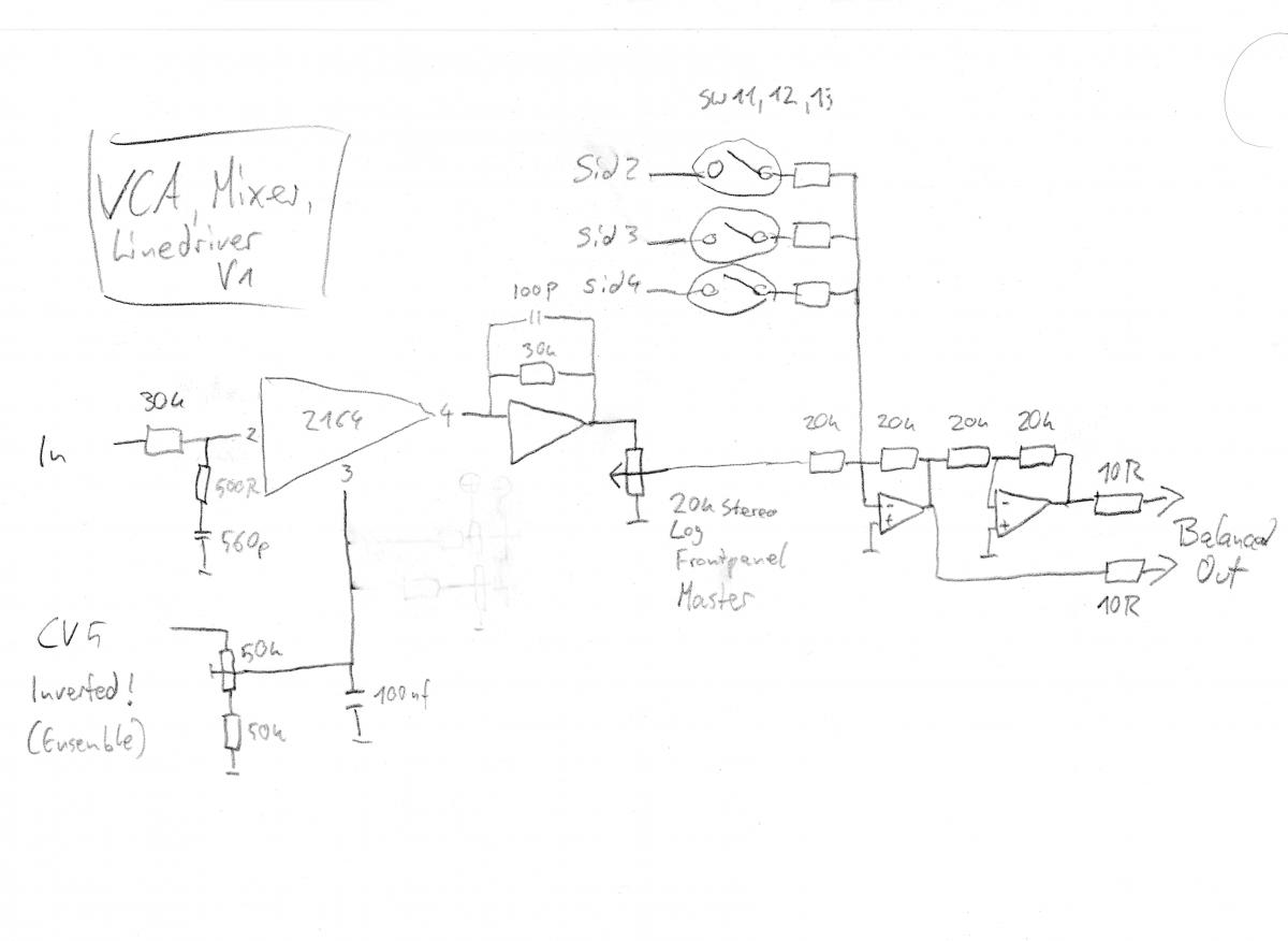
- Main VCAs, mixer and balanced line drivers
Here are some basic waveforms. You hear three short clips with modulated wavefolding. Then there is a short sweep of distortion and then a couple of FM waveforms. All were generated using a single triangle oscillator.
--sorry, file was to big, have to bounce it again----
Although this is still a work in progress i already have a bunch of schematics with tested values so i thought it´s about time to share a little.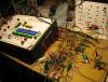
Soon after i hooked up my first Sid-Chip to a core module i was hooked up myself. I spend a lot of sparetime over the last 6 month, thinking what could be possible, what could be usefull, what could be fitted into the MB_SID concept.
The analog CV-options and triggers are perfect. Thanks TK.
I use analog filters and VCAs, they eat up 6 CV channels.
Leaving 2 CVs and 8 triggers.
Not much if you are used to modular synths. But that was part of the job- selecting the right blocks to get the most out of what is available. And i soon realiced that you would rarely need any more.
Oh - and everything is saved with the patch!!!!!!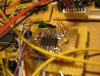
I tried a bunch of circuits and ideas and came up with this collection of building blocks.
Among the design goals were:
Usefull addition soundwise (very subjective)
Low parts count (more or less)
Effective controll with one CV per stero side.
All CVs are 0-5v, the DAC can drive 2k load so i dodn´t use any buffers. Of course a complete AOut Module can be used if you like to try any of these circuits, but if it is calibrated to 10,xx volts the cv inputs should be adapted. If you know what a voltage divider is this should be no problem. I use trimmers anyhow, but with series resistance to taylor the trimmer to a more precise action. Lowering or raising the coresponding resistor does the trick.
Effects can be switched in individually, but share the same CV so the same modulation will be applied. Can sound very cool, but normally one at a time is enough for a certain sound.
There is also a mode that controlls two sets of effects - in mono.
Have i said i love the modulation matrix?
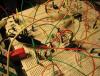
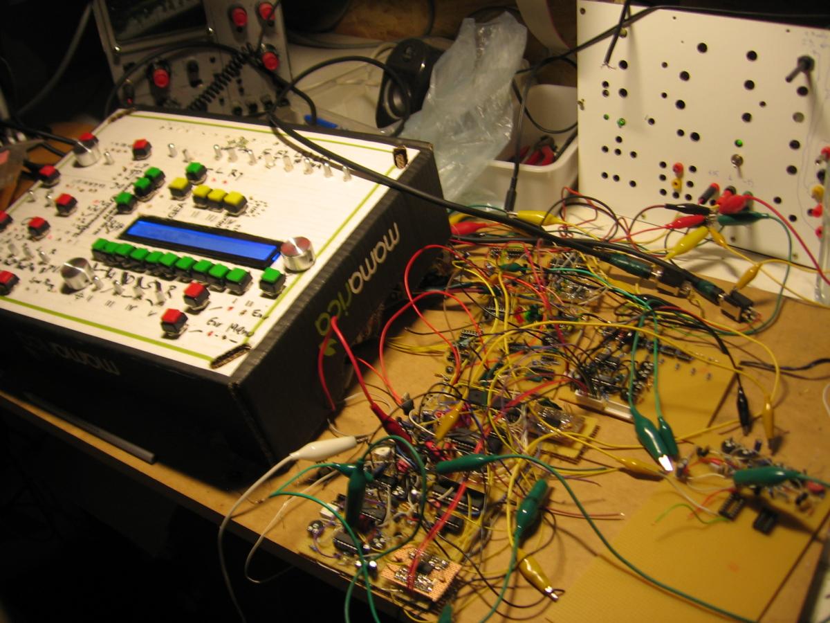
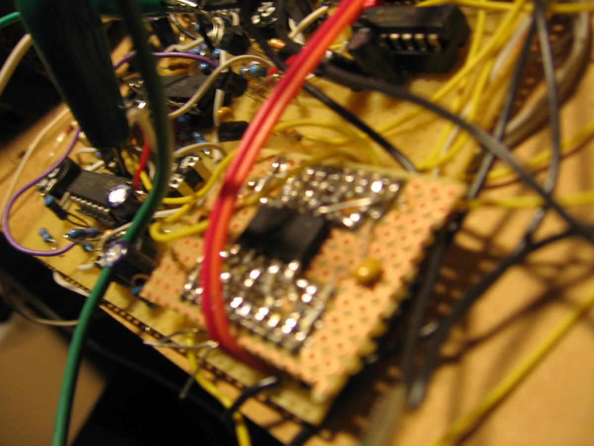
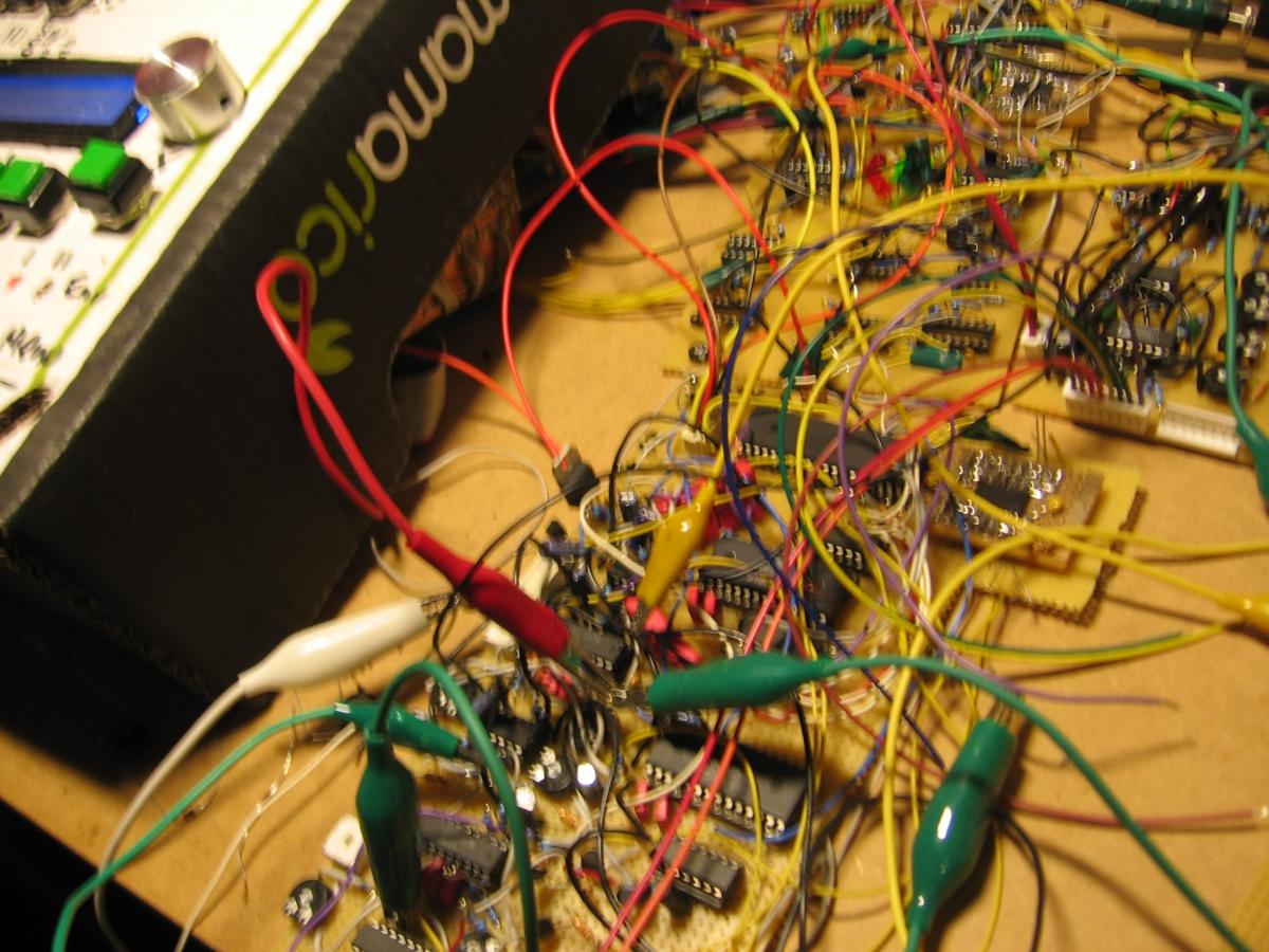
Sorry, i have schematics, but no board layout. I am a veroboard guy... I refuse to learn any layout software...
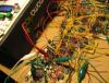
I am happy i found a good way to solder SMD. I carefully bend every second leg upwards. The remaining pins can be soldered nicely to a veroboard. The bend pins will be soldered using short bridges (cut resistor legs). I use this a lot to perform crossings (like multilayer) or connect ic pins, etc. Quite sturdy, of course you musn´t apply preasure, so whatch out when changing chips. It´s definitly quick compared to strapping wire.
Anyways, i like working like this when there is a good audio book around. Kind of fun looking for the shortest signal path as you go along filling the board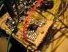 .
.
In the current state i have implemented and build (in stereo):
- CGS Simple Wavefolder with some adaptions
- Filter FM
- Highpass blend for external LP-Filters using same VCA as Filter FM
- Voltage controlled Overdrive with volume compensation. Needs improvement.
- Switching of modulation Signal for FM sounds. Making Sid L the source for both signal channels, Sid R the modulation source for Filter FM.
- Stereo/dual mono CV mode
Only checked out, under construction:
- Noise for external Filter
Todo:
- Tweak the overdrive for less noise and better Bass-responce
- build signal switching circuitry
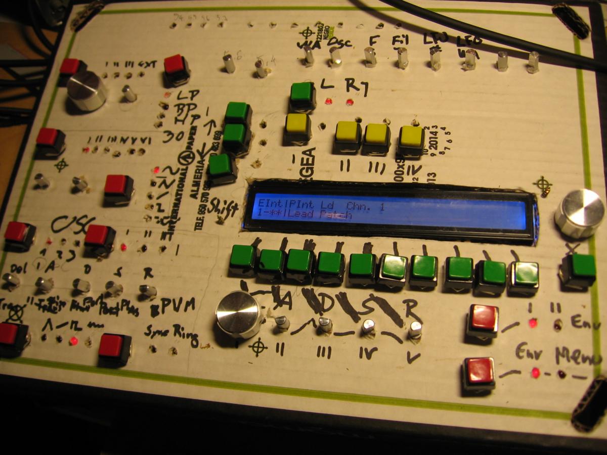
- design frontpannel and CS
- decide if F2A should be used. This is a problem in conjunction with the 8580 requiring calibrated log mode. Alternative would be to include independent controll for CV 1 and 3
- put everything in a box with psus
- decide what could be ommitted
- Build Stereo Sid 2,3,4....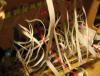
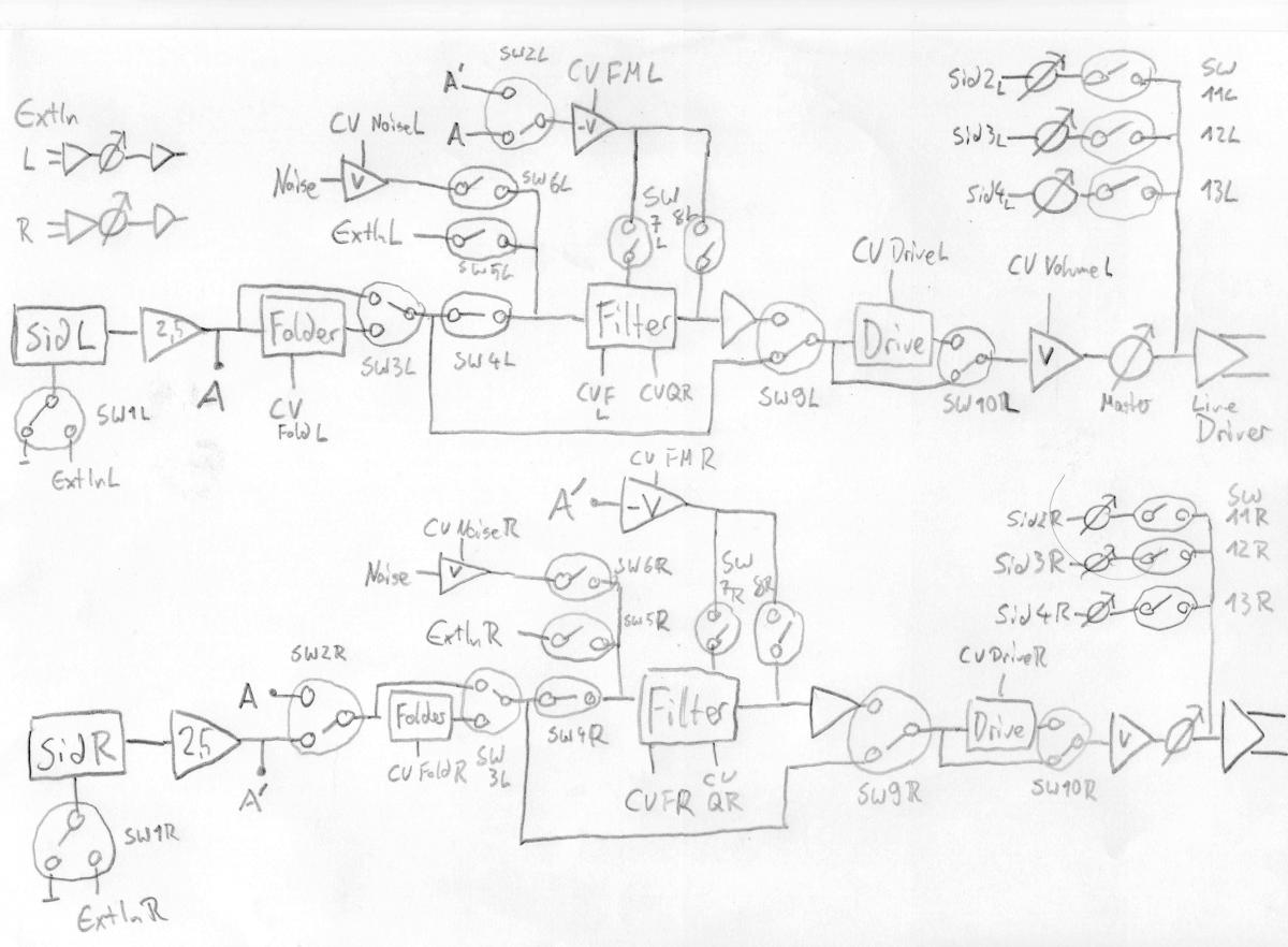
Here you see a block diagramm of the signal flow.
-A buffering amplifier brings the sid output to a more roboust level.
-Folder, Filter and Overdrive are chained and can be switched in and out (see extra diagram below).
- FM and Highpass are part of the Filter-schematic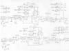
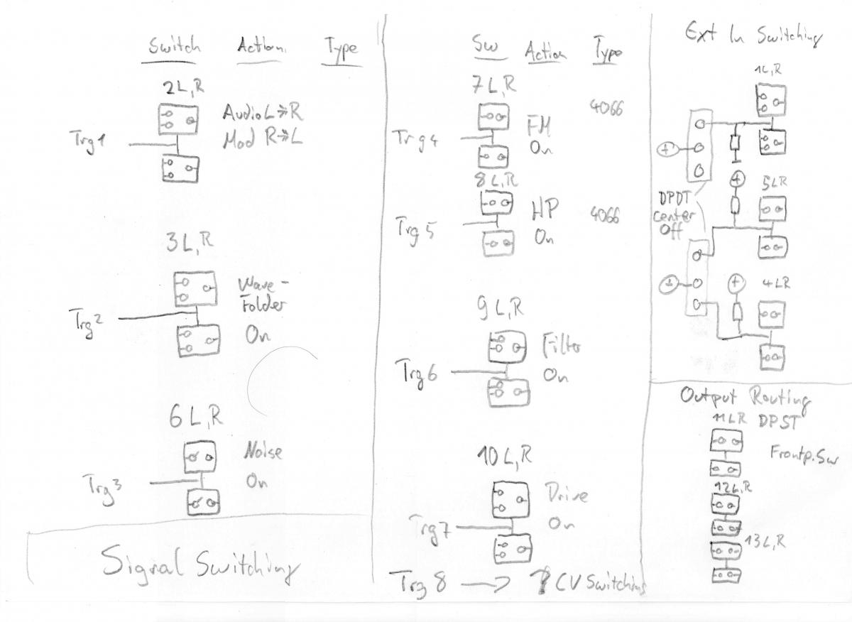
Signal and CV switching
Most of this is propably self explaining. Switches controlled by the Gates from MB_SID. Stored with the patch. Very nice!
Switches are not selected yet, but i´ll propably go CMOS 4066 or 4053 for CVs and some Maxim Chip for Audio-Signals. Max 333 ACPP might be the choice. For 5.20 € at reichelt you get 4 SPDT switches that can be powered with up to 30v. For a compressor i would always use a relay, but this is a synth...
Maybe powering the 4000 series cmos chips from +-7,5v would be smart. makes the PSU more complex though.
I still have to test how they perform with AC-coupled signals when powered from 12v single rail.
SW 2 is different for L and R channel.
This will route the left Sid to both audio channels, making the right Sid the MOD source for FIlter FM of both channels.
SW 1,4,5 are controlled by a center off, DPDT switch on the panel.
They provide three modes for external signals:
EXT to SID_input
EXT to CEM3379 filter directly
EXT to CEM3379, Sid disconnected from filter (but still available for FM!)
To be honest, this should work, but i might not build it. If i really build 4 stereo voices, they could be fitted differently.
SW 11,12, 13 are also hardware controlled for routing Voices 2-4 to the Main out.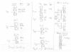
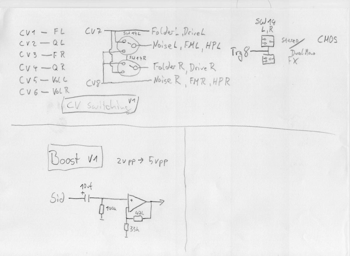
A Gate is used to split CV 7 and 8 between L and R channel (each cv controlling every active effect) - or - direct CV 7 to Wavefolder and distortion, CV 8 to the other effects - on both channels.
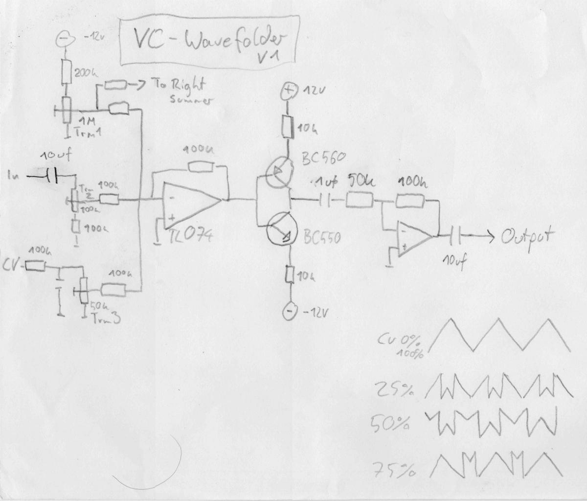
Wavefolder:
I found this little circuit on CGS. Really fascinating what it can do.
http://www.cgs.synth.net/modules/cgs52_folder.html
I found that, although this will react very much on different input levels, it sounds best when a defined level is used (so no VCA is required). I calibrated mine to work perfect with a single oscillator. Using multiple OSCs sounds interesting as well, but some sounds are "broken". Luckilly oscillators can be turned down with the Sustain.
Instead CV is applied as an offset. On the schematic i tried a drawing of the waveform at different CV levels.
It sounds a bit like a phaser and a bit like pwm for triangle and saw.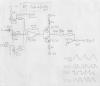
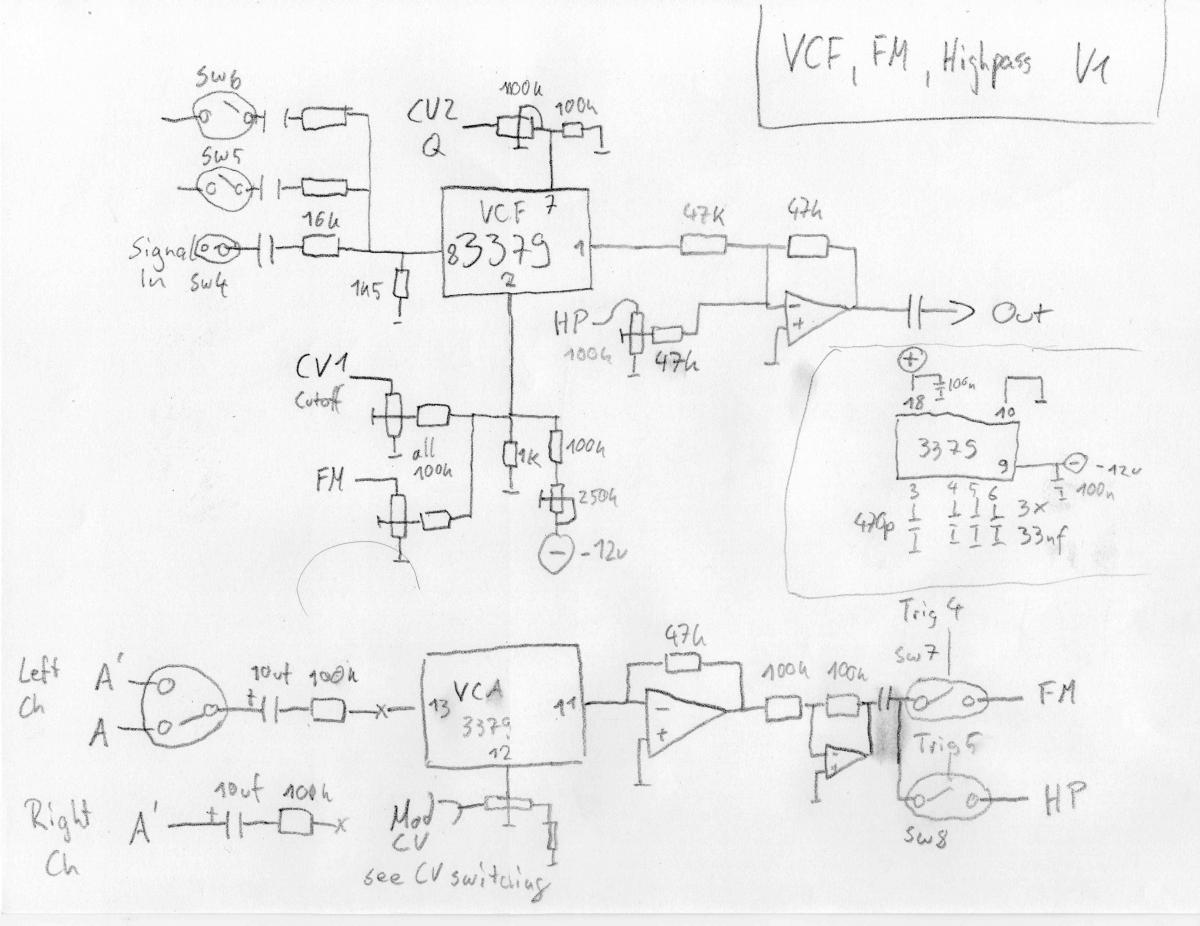
Filter, FM and Highpass:
Depending on Switch SW 2 L, R a modulation signal is routed to an inverter and VCA. FM is generated by switching the VCA output to the Filter Cutoff pin. HP by summing the VCA output with the filter Output. Since the VCA delivers an inverted signal it will cancle out below Cutoff - creating a fade to a more or less Highpass responce. Note that, if switch SW2 is on, or the wavefolder is active, things look a little different.
The rest of the Filter is more or less off the CEM3378/3379 datasheet. I settled for a slightly higher drive, giving this filter a little more grit.
Of course the same circuitry could be added to any VCF.
I have not yet implemented the Noise. I tried it once and liked having white noise as an alternative to the sid noise sound. Also having an extra VCA for noise is nice to have. Schematics for analog white noise (using a transistor with open collector) are on the web.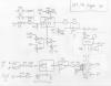
Overdrive
This can be seen as first design concept. I have to do something about the noise, propably by chaining more clipping diodes, thereby raising overall level.
It could also use some basic filtering at the output.
The overdrive itself is made by the opamp with the diodes in the feedback path - forming an unsymetrical sof clipper. You know this from the guitar stompboxes...
The first VCA acts as a voltage controlled drive-pot. The trimmer around the CV opamp will set a bias at low level so with no CV applied there will be close to none distortion.
Volume compensation is archieved by applying a portion of the CV controlling the Drive (first VCA) to a second SSM2164 VCA but without the inverting opamp, turning it down as volume raises. Remember SSM2164 is at unity gain at 0v cv and will turn down with a CV going positive.
This works very well, it can be trimmed to taste so that the percived Volume is constant or if you like, slightly raising.
If i had a 9th gate i would make it switchable pre or post filter.
But that could also be solved by building different Voices.
Pre filter is nice as you can controll the harmonics, Post filter has a more agressive touch and gives cool clipping of filter selfoscillation.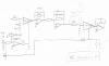
VCA and Mix
Nothing special here, only maybe that i use an unbuffered CV that is inverted in the ensamble settings. Nice feature!
Since my Studio is all balanced this is what i added for outputs.
compensation caps (47pf) across the output opamps feedback resistor are required and missing in the schematic. I use NE5532 for it´s 600 R drive capability.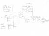
Sorry if this was confusing, i am a bit hit by how much info this is myself...


Am i allowed to sell stuff containing a midibox ?
in Miscellaneous
Posted
Old thread but i just saw this.
Beautiful work and idea! I bet the kids love this. I work at a school also, got to show this to my boss!
Is it running ableton live?