

jrp
-
Posts
221 -
Joined
-
Last visited
-
Days Won
1
Content Type
Profiles
Forums
Blogs
Gallery
Posts posted by jrp
-
-
wow! you are incredible.
I read your first post and was already forming thoughts like "oh, what a pitty, i hoped it was a simple adjustment". No surprise, i cannot "read" assembler but i have read about it....
And then that second post :smile:
So you changed it by altering mios8 if i understand correctly. Will this have an effect (positive or negative) on other applications, like MB64e?
I´ll try this as soon as possible!
Regarding Steps: I recorded some sounds today and was tweaking the synth, quickly editing. Fast mode feels a lot better to me now. Some of the stepiness i heard was exagerated because i was controlling external vca that was poorly calibrated and was missing a smoothing cap at the controll pin.
-
the demo makes me think i should give feedback another try.... like the scream it gives.
-
If you start experimenting it is important to use a cap to ac-couple the signal to the input. SID input pin is floating at half supply voltage, not ground.
i am designing the rest of my analog signal path right now, so this has to wait a little, but i am interested in trying.
Basically it allows you to process analog signal like drumloops with all the goodness the SID (or external voltage controlled effects) have to offer. So it´s really cool! I already implemented this with my external filters. You can imagine what you can do with a drumloop, tempo synced LFOs and envelopes, using filters, distortion and vcas....
I expect the sound of the sid input to be a bit grainy compared to using an external filter. Maybe it has a cool vibe to it when going beyound the 2vpp signal level pointed as maximum in the datasheet. And the sid filter of course...
I definitly want to check it out, but as i said, for now i am at the other end of the signal chain so to speak.
About feedback: With my 6581 this does very little but adds a bit of grain, distortion and boost you might find pleasant. 8085s will go into oscillation when in BP mode.
I decidet not to implement it as i am using external filters and a lot of much more powerful voltage controlled processing so it had no reall benefit to me.
If i would implement it it could be considered to use a fixed feedback level. At least for me i had the feeling this was more of a turn on turn off type of effect. - In other words, my pot during experimenting was either fully up or down when playing with this.
-
Yesterday night i had the time to play with my MB_SID and get a better impression of the new feature.
The Speed is actually good - turning an encoder two times for the whole range still feels very resposive. In audio ranges are very big...
The "steppiness" does not feel so good, unfortunately, especially when trying to do small changes.
It seems to me that the transission between slow and accelerated speed is quite low. When an encoder is turned slowly the increments are smooth and slow. Go just a little faster (but still quite slowly) the threshold is reached and speed is accelerated. If this threshold would come in a bit later that would feel much better.
-
We shoud stay on topic, you are right.
About different speeds for controllers controlling the same range - this is not really necessary. But it could come in handy to really tweak the responce of the CS - i cannot really tell by now.
I am also really interested how other users feel about this topic, and what types of encoders they are using. I was searching the forum a lot before because i thought i simply had bought the wrong encoders.
Thanks for pointing me to the right direction. I can very much understand your point not providing this as a general configuration option. I find it also very positive if some hints are given where to look instead. Might be a lot of trial and error for someone like me, but it gives the interested a very little gasp on how a sourcecode like this is functioning.
In CS_Menu.inc i found this, i figure this is the place where the responce could be adapted for different types of encoders:
CS_MENU_EncSpeedSet_ModVal_GT1F
;; max value > 0x1f: set fast speed depending on range:
movf CS_MENU_PARAMETER_MAX_H, W
andlw 0xf3
bnz CS_MENU_EncSpeedSet_ModVal_GE400
movf CS_MENU_PARAMETER_MAX_H, W
bnz CS_MENU_EncSpeedSet_ModVal_GE100
movf CS_MENU_PARAMETER_MAX_L, W
andlw 0x80
bnz CS_MENU_EncSpeedSet_ModVal_GE80
movf CS_MENU_PARAMETER_MAX_L, W
andlw 0xc0
bnz CS_MENU_EncSpeedSet_ModVal_GE40 -
i could only do a quick test right now and i can say cutoff and depth work much better now! This is really cool! Could still be a little faster for very fast wide speeps, but on the other hand that would be best done by a pot anyhow... so i think your efford on this toppic was a great success.
Is there a way for the user to configure the reponces further within the firmware to adapt for different encoders or is this simply to difficult?
I have the impression that envelope2 is messed up/not working on some of my patches, but i assume this is due to some error on my side again. These patches had been made with a modded firmware where i had dec 1 and dec 2 flipped in the menu for conventional ADSR responce.
Unfortunately i´ll propably not have any time over the weekend for further testing. But for now, it feels really good tweaking the knobs. Envelope is working when setting up a new patch.
Regarding envelopes (please just say to complex - i don´t want to steal your time - and i wouldn´t want to start a new thread asking for stuff): I have been searching the code with no success for a way to double the envelope1 depth within the modmatrix. Right now i assign env1 to source 1 and 2, using 1+2 opperation like described in the manual, to get a full-range cv sweep to my vcas. So to add more amplitude modulation (eg multiply env with velocity or a lfo) an additional modulation path has to be used.
Also i was trying desperate to change modulation target osc pitch 1,2,3 to ext 7,8,Q simply couse i use these more and hate not using half the cool modmatrix.
Not important, it works nice this way, but i just can´t resist trying to tailor your application to my setup as much as possible. Call it an obsession ;-)
No idea if these are easy tweaks or require larger code rewrite. If i get a hint how to figure it out i would be glad to write a easy to follow step by step guide for the wiki. I see these things will make the application incompatible to existing patches and are only for a user who can live with that.
-
I just played with this a bit more. My setup is including CEM3379 filters.
Sweep could even be a bit faster than speed 7 but it´s nice like this already. Unfortunately tweaking the knob does not produce a smoth filter sweep. It sounds more like a glissando (=stepped).
-
The problem i see is that with different encoders the responce will be different. Combining SID with MB_NG sounds very exciting indeed.
About my SID not outputting sound with the new firmware: I simply forgot that my ensamble settings were overwritten by the upload (for now i have only one bankstick - i´m prototyping analog enhancements at the moment). I was simply sending on the wrong channel ;-)
-
Sorry, i try to stay on topic, but this is just too exciting...:
In addition, I will add a "CC dump request" which will allow to synchronize a MBNG with the current patch CCs.This sounds very interesting. So it could bring ledrings to our sid? Among other things... Analog pots in snap mode maybe...
But isn´t a CC always a 7bit value?
I feel especially cutoff modulation will suffer from lower resolution. The range of sound-frequency is simply enormous.
In the sysex implemention i read this: Is it not the same? I was scratching my head about the possiblilities for a CS in combination with MB_NG
01/b) F0 00 00 7E 4B <device-number> 01 08 00 00 F7 Request the current patch edit buffer (direct read from RAM)
-
Hello,
Thanks for putting this up!
The testmode works perfectly but i am missing sound from my sid after uploading. Is that intended? I had to test the speed modes relaying on display rather than sound feedback. This makes me a little unsure.
Just for my understanding: The firmware will read how fast i turn the encoder and act accordingly, so there will still be full resolution, no audible steps, right?
The firmware seems to switch between two speeds as soon as a certain turning-speed-threshold is reached. Is this correct?
Here are my findings with 20 ppt detented encoders from unknown manufactor (i assume these values will differ if other encoders are used):
First of all: I am very happy!!!
For Fast mode:
- Cutoff:
Speed 7 - it still takes 2 full turns to cycle through the whole range. So it could even be a bit faster. But since i couldn´t hear anything i don´t know if it will feel smoth. But i know it is actually handy to dial through the whole range with the twist of a finger sometimes.
If i consider an additional analog pot for tweaking (from the knob function or from outside via NRPN) than 7 is propably perfect for normal editing.
- Resonance:
Speed 4 - 360 deg turn. Could be a little bit faster, but seems best value for me.
Speed 5 - a bit faster feel than a analog pot would give. That makes it too fast definitly.
- Depth:
Is actually the same range as resonance, right?
I would use speed 4. Maybe 3 is better since it is split around 0 so it will normally require less fast tweaking. Really would like to hear how it reacts.
4bit Sustain:
Speed 1 is nice, perfect would be inbetween 1 and 2. Actually normal is also fine for this :)
Slow Mode:
I personally propably would not use it as the ecoders already sense the acceleration. Turning the pot slowly works well.
Bisides that, for all the 10bit, 8bit and 4bit parameters Slow 0 or Normal (is it the same?) seemed useful.
Is there any chance these values will be adjustable by the user in a final release?
-
Hello Thorsten,
Thats very nice! I would be glad to do some testing! SID is awesome!
-
changing the code is really simple. Just change the line and recompile. I already tried it but for me it changed nothing. So it would be really interesting if it´s a mistake on my side or if it simply doesn´t work like that. Maybe just a little mistake in the discription (although i would normally trust tk blindly).
So people, if you are interested, just try it and tell us how it went. If it works for you i´ll have to keep trying and see what my mistake was.
Besides, i still belive using a MB_NG or MB_64e to handle the controllers would give more options and would be much easier to tweak for best feel and resolution.
The only thing that troubles me is that a second core running the encoders or pots would have to determine what SID (1,2,3,4) is currently active so data will be transmitted on the right channel. Luckily each SID engine sends a dout flag when active, that´s where the SID LEDs are connected. This could be used to let MB_NG switch to the right midi channel(s).
This would also mean that channel assignment would have to be fixed in the ensamble settings. So a Midi router would be required since we want to be able to play each sid individually or unisono from one channel.
-
possible we are just using the wrong encoders?
I built my cs prototype with cheap encoders i ordered from china (about 15 pices for 5$...). They are detented (24 clicks) and detents cannot be removed as the detents are made of the switching contacts.
Somewhere i have read that by using nondetented encoders the resolution is much better, although i don´t see how this will work as they should still only have 24 impulses per turn (right?).
Maybe someone has some input on this and can recomend a better suited part.
-
I have been working on some minor code changes (mostly regarding new buttons and encoders) and can tell that it´s not easy. Assembler code is easy to mess up i guess... But i am no programmer, so maybe for you this is more straight forward.
Anyway, if there are alternative solutions that´s fine with me. And NRPN offers full reolution for all parameters so it´s the best choice anyhow.
I see a good idea behind the cc handling for several situations:
If you use a modwheel, do you want it to change your patch?
Or if you save after playing a soft note with low velocity controlling volume, do you want that low volume being saved with your patch?
Or you have a joystick for live tweaking, that is also good to have independent of your edit buffer.
I might start with some experiments using a MB_NG or MB64e. I recently found out TK has implemented a way to send NRPN with meta events...
But it´s a long way till i get to this, currently i am tweaking my analog voltage controlled SID channel and that is still a lot of stuff to fix and callibrate.
-
in fact the 2164 is really one of the easiest destroiable chips i know. Next in line from my experiance is LM13700 and SSM 2018...
You can wreck it by simply touching it if you are carrying static charge. And most likley you are... It is good advice to ground yourself (eg by touching a grounded metal case of some equipment) before handling the chip. Don´t forget that this also counts for components that are connected on the pcb. I killed more than one of these chips simply by sticking a resistor into the breadboard while experimenting.
Since i do the grounding trick before touching a part like this i never had any issues.
There are a couple of sellers on ebay who still offer the ssm2164 or the coolaudio replacement.
-
So do i understand that you want to remote controll your sid because you are not happy with the encoder speed?
It´s the same for me. I have to turn encoders like 20 times to sweep through the whole filter range.
Unfortunately MB_SID does not provide any different speedmodes like the MB64e.
A few threads down in this forum TK explained how to change the Shift button so that it´s function on encoder speed is reversed. If you try this, please tell us how it went. For me changing that line of code unfortunately did nothing (strange).
I am considering diving into the MB_NG world to provide controlls for a couple of features. Analog pots sending NRPN would be my choice.
Freq, Reso, 2* ADSR and depth, EXT_CV 7, EXT_CV 8, maybe even direct controll for LFO 1-3 are the controlls i am thinking about.
combined with some encoders from the original cs this would be killer for fast tweaking of sounds!
But i could not try out how this behaves yet. EG, if a NRPN message will automatically be routed to the selected Sid (1-4, L, R, LR) no matter what is set in the ensamble.
I kind of fear that building such a "programmer" would require to read out the ensamble channel settings from the sid, check what sid is active on the cs by looking at the pins driving the sid leds and then decide what midi channel the data has to be sent on. That shure would be possible, but rather complex for a programming noob like me.
-
You could also consider to use the first two outs for mixing. Channel 2-4 would then need a dual switch to connect to the mixed output. This way you can easily change between using individual outs or a mixed output without replugging any cables.
Try these old opamps if you like the sound it´s fine. YOu should check with a scope if these start to oscillate when driving cables. As for me, i would rather use those in a distortion effect of some kind rather than using them for main outs of any device.
You want something that is capable of driving any real world load easily. 5532 is a good choice as it´s cheap, low noise, stable under usual conditions and can drive 600r loads. So your sound will be uninfluenced by cable length and the load it sees.
Of course TL072 is an option often seen, but it is much weaker so the outputs are more prone to picking up noise and hum compared to the lower output-impedance chips like the 5532.
-
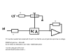
Your schematic looks fine, although you have to consider that the ssm2164 will be at unity gain with 0v and attenuate with a cv going positive. around 3v should be enough to completly shut off the signal. So your cv needs to be inverted (easiest way is by inverting it in the ensamble settings) and scaled down. I don´t know if the trimmer on the Aout module is sufficient in it´s range for this (i am driving my vcas with the dac directly, TLV5630 outputs around 5v and can drive 2k).
If you cannot scale the cv down to the needed range with the trimmer you need to add an aditional voltage divider in your cv line. Like the trimmer in my drawing. Impedance of the divider can be anything from 10k to 100k, the VCAs are truly voltage controlled so impedance doesn´t matter. You could try this :
Aout --- 10k --- SSM2164 cv in
|
10k
|
ground
this will reduce the cv from the aout to one half of it´s original range. Then adjust the trimmer with cv at full level (volume=0 when aout channel is inverted) until the sound is completly vanished.
If your cv range is too high the notes will be delayed as the envelope will attack through too much silence in the beginning.
If the cv range is too small you will still hear sound even though the note should be turned off.
I left the mode pin open. For a synth neither distortion nor noise in the order to be expected will be of any concern. I doubt that you´ll hear any difference.
-
same for me. integrating mixing is very convenient. Although i have a 40ch mixing desk for all sorts of tricks, it´s sometimes nice and handy to be able to have all sids mixed into a single out from the cs.
-
Yes, it should work. I have a mixed setup as well, but with a selfmade psu.
+-15v get regulated to +-12v and + 9v
5v is generated from an additional 9v transformer. Current draw is too high for making the 7805 drop some 10v if you use an lcd backlight and maybe additional slave cores and lots of LEDs.
Might even be good to have a 7805 for each slave core.
Make sure that you don´t connect 9v to 12v! 7809 can be driven from the 12v line with no problem. Current draw should be rather small, but still it´s good practise to use a heatsink.
-
from the cc implemention chart (sid manual):
The CC implementation covers the most important parameters at 7bit resolution, so that they can be easily accessed from a
DAW or a common MIDI controller.  CC changes are non-destructive and won't affect the edit buffer. This isn't a bug, but a feature!
Means: your edits on the Control Surface won't be overwritten by incoming CCs, but as an effect they won't be displayed on the LCD,
and you won't be able to store changes made via CC as a new patch.
I still have a lot of old pics here, so if anyone has a hint how to make it send NRPN on pot movement that would be great! In 8bit programming section there is an example for sending cc on pot movement (first example in the list). It is propably necessary to make it look what sid is currently active (simply by looking at the dout pins driving the sid 1-4 LEDs), so that data can be sent to each connected core. Not sure how this has to be implemented. Propably hard if different ensambles with different midi channel mapping will be used...
In this case it´s propably best to have the controll pic handle midi mapping and use just a single ensamble on the master sid.
What i am thinking of is a box that will controll around 10 to 16 parameters from analog pots in full resolution. I was nevery happy with the feel of encoders for tweaking the synth. I am a studio user, so i wouldn´t mind the parameter jumps. And there is still the option to use encoders alongside.
-
i found this in the documention somewhere: CC will not alter the edit buffer or something like that. I think it will work if you are in edit mode? Can´t find where i read this right now.
Or you have to use sysex ot Nrpn.
I am interested in the same as i wish to add a lot of analog pots to my sid (for envelopes and filter, maybe also some lfos). I guess this can be done with MB_NG, i think MB_64e can only send cc (?).
-
All can be done, it depends on your needs.
My sid has independant outs with stereo volume controll on each voice. Voices 2 to 4 have a little switch that mixes them with voice 1.
I used a simple inverting opamp mixer as can be found using google.
-
in fact the osc-envelopes are independant from the main volume that is forwardet to aout.
So yes and no. If you activate GSA the oscs will always be "on", playing at their sustain value. So in fact if A=0 D=0 you can set the osc-volume with S=1 to 15.
It is also possible to use without GSA, then you should just adjust the release so that the osc wont be turned off before your vca modulation has fadet out the note.
I built my ssm vca on veroboard and never bothered to draw a detailed schematic.
I would recoment having a look into the datasheet, in the meentime i try a little drawing... I am working on a complete analog channel with some effects right now, but that´ll take some time...
The schematic you linked will work, but it´s more than you need.
Since the cv(aout) can be inverted in the ensamble you only need a trimmer to scale it down when driving the vca directly.
Note that complete Aout module is not needed. I drive mine directly with the DAC connected to the core.
i attached a little drawing.

Optimizing Encoder Behavior in MBSID Firmware
in MIDIbox SID
Posted
i just did a quick test for now as i am off for work. I am not quite sure if i notice a difference. Was it a big change on your setup or rather subtile? My test is trying to set cutoff to 800, i most often get jumps like 76f to 830 with just 3 ticks of the encoder unless i turn very slowly.
Do i need to upload the new mios to all slave cores as well?