ultra
-
Posts
832 -
Joined
-
Last visited
Content Type
Profiles
Forums
Blogs
Gallery
Everything posted by ultra
-

MIOS32 Voxel Space Graphics Demo on 256x64 Graphical OLED
ultra replied to Hawkeye's topic in MIOS toy of the week
i understand what you mean with your algorithm and left lead and i'll implement that later. first, i need a method to store font information. i figured that 16x16 space is good for the maximum character size. this allows a u16 array[16] to be used to store the information. then i'll analyze the actual number to get the bits out of it. how does this look for a beginning to storing the actual fonts? this format might make it easy for others to add their own fonts: // describes various fonts which can be up to 16 x 16 px wide. // number of characters per font is 94. // character index has a range of 0-94, which corresponds to chars 32-128 on the ascii table. it's necessary to subtract 32 from the character code to get the correct character. struct font_char { u16 bitmap[16]; u8 left_lead; u8 width; }; struct font { u8 *name; u8 height; struct font_char chars[94]; }; struct font fonts[] = { /* first font */ { // superpoint square { // space { {0x00, 0x00, 0x00, 0x00, 0x00, 0x00, 0x00, 0x00 0x00, 0x00, 0x00, 0x00, 0x00, 0x00, 0x00, 0x00}, // bitmap 0, // left lead 2 // width }, /* second character, and so on */ /* ... */ }, }, /* second font, and so on */ /* ... */ }; keep in mind i'm just learning about how to use structs now, so maybe this is the wrong approach or the code is simply wrong. -
MIOS32 Voxel Space Graphics Demo on 256x64 Graphical OLED
ultra replied to Hawkeye's topic in MIOS toy of the week
hawkeye, right now i don't have any code that would be useful to anybody else, unless they wanted to use my specific format. but i'm finding it limiting even for myself, so i'm going to work this afternoon to make it more universal. my current method is to store an array[64][256] that simply contains 1's and 0's to tell whether or not a pixel should be on or off. this array is used for the entire region of the display. i'm going to change that to store 0-15 so the shade will be stored instead, which is why i asked my question earlier. then i wrote a simple loop to read four slots out of the array at a time, and test them for on/off and write out the correct 2-byte codes to the display. it works great and i won't need to change it much for displaying the overall picture, except for changing the algorithm a little bit to account for shades. maybe this is the standard way of doing this, i don't know. i just started working out what makes sense to me as i don't have any previous experience in writing a display driver. to draw my font, i wrote code specifically that would work with this font. i'd like to do it an entirely different way though, which i'll describe later. i have 3 functions to draw them: write_h_line and write_v_line will 'draw' horizontal and vertical lines into the main array based on starting x/y coordinates and length. a third function, write_pixel will write a single pixel based on x/y coordinates. calling them has to include whatever offsets i want (tall/short letter, etc). so when i feed in a string like "this", it loops each character, writes each to the main array, and puts an extra pixel for spacing. i just keep a running counter to show where the x-coordinate is for the start of a letter. i'd like to just store fonts in different files. i like to have space available on both the top and the bottom to account for letters such as 'h' and 'g'. so for example, if i account for a font being 11 px tall (7 for a short letter like 'o', two px above that for a letter like 'h', and two below that for a letter like 'g') and want to write 'h', it'll be stored like this: 1000000 1000000 1000000 1111111 1000001 1000001 1000001 1000001 1000001 0000000 0000000 that's essentally an 'h' in the superpoint square font. but the same engine could easily read other fonts if the 1's and 0's (or actually, the value representing the shade) was stored for it. my biggest setback is that i'm really not that great at C, and OOP makes more sense to me. i want to store data that contains the following information: font name overall font height each character of the font, which has the following: width (if even necessary) left offset (i posted a pic below to show what that means) an array storing the 1's and 0's (or shade values) that can be returned to the function calling it,a nd then inserted into the main array i think i just need to learn more about defining types to store this data, and using pointers to make the array usable. i'll figure that out this afternoon maybe. once this is done, and a small library of fonts are stored, the programmer or user could just select a font based on name, then size (i find that odd # sizes work best), and then write the letters where they want. also i'm wondering how to handle words that are bigger than the space allowed (i want to code this to let the user define regions like you said), so if a word is too wide, it gets truncated. my thoughts were 'truncate' would turn into 'trunca.." if there wasn't enough space. if i go that route, i already have a good idea of how to do it. also, i'm going to incorporate left/center/right justification based on the user defined region. anyway, i'm not really looking for you to answer anything unless you can tell me what's best for storing/retrieving the font data. i'm just throwing out what i've figured out so far and hoping for somebody to tell me if i'm going about it the wrong way. the attached image shows what i mean by 'left offset'. the lowercase 'j' got it's own bit of code, which (if it's not the first char) backs up the counter to make the bottom part of the 'j' wrap around the previous letter. maybe switching from windows to a macbook has made me put too much emphasis on style. :P
-
MIOS32 Voxel Space Graphics Demo on 256x64 Graphical OLED
ultra replied to Hawkeye's topic in MIOS toy of the week
this is exactly what i was looking for, thanks! -
MIOS32 Voxel Space Graphics Demo on 256x64 Graphical OLED
ultra replied to Hawkeye's topic in MIOS toy of the week
hawkeye: is there some pattern to the shading? i have a 2d array that stores information on individual pixels. this doesn't include what value i get when both pixels are on. so if array[0] stores the value that gives me only the left pixel at a certain shade, and array[1] stores the value that gives me only the right pixel at a certain shade, is there an operation that can combine the two to give me two pixels at the same shade? i hope i'm clear on this. thanks -
From the album: MIDIbox Live
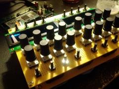
this is a prototype design for the second ableton live device i'm working on. it will integrate with whatever instrument you're using, and also allow for designing and editing clip sequences, among other things. i have a lot of ideas up my sleeve for this one, and consequently i also have a lot to learn. -
From the album: MIDIbox Live
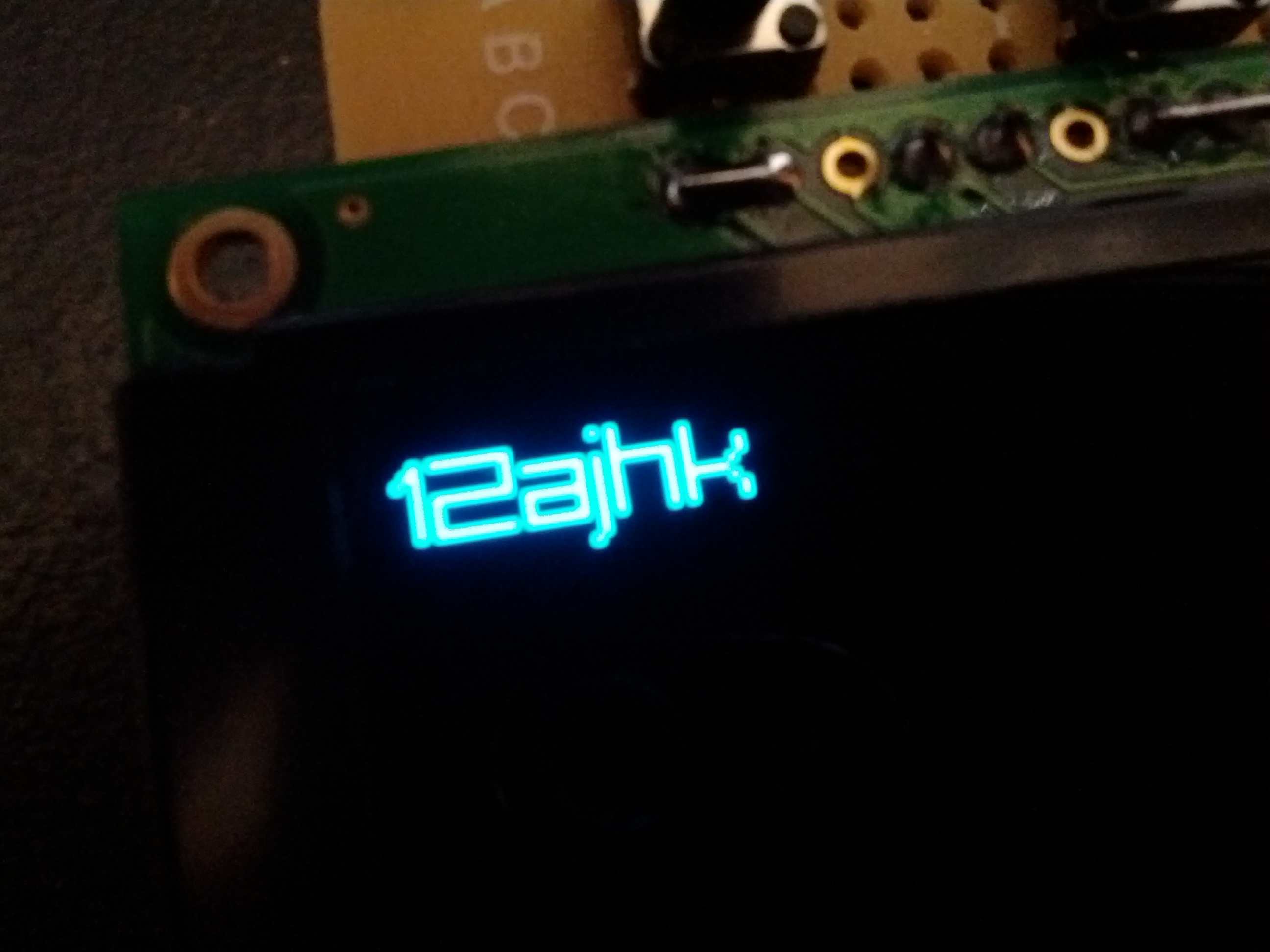
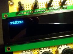
writing a driver for the newhaven oled. i'm coding the font based on one i found on the web called superpoint square. i like it a lot. i plan on coding other fonts in the future. -
MIOS32 Voxel Space Graphics Demo on 256x64 Graphical OLED
ultra replied to Hawkeye's topic in MIOS toy of the week
got some things working now. :) -
MIOS32 Voxel Space Graphics Demo on 256x64 Graphical OLED
ultra replied to Hawkeye's topic in MIOS toy of the week
i'll try the caps later. for now i'm having a lot of fun with this. i got some nice single pixel wide horizontal meters written (i ditched the idea of having a meter behind text) with a light gray bar for the entire meter, and a brighter one showing the value. can be put anywhere on the display using parameters. i think i might go all out and make my own custom font and everything. that way i don't have to have fixed width characters and i can get more info from the screen. wheeeeee! -
MIOS32 Voxel Space Graphics Demo on 256x64 Graphical OLED
ultra replied to Hawkeye's topic in MIOS toy of the week
that's exactly the layout I'm looking for. let me know when you get something done. I'm just not experienced enough to write something from scratch. edit: forget that... i'm gonna figure this out. after looking at your test screen code, it's a lot more clear. :) another edit: using the test screen, i can see the flicker is really bad. hopefully only some capacitors will help. do you recommend a value? -
MIOS32 Voxel Space Graphics Demo on 256x64 Graphical OLED
ultra replied to Hawkeye's topic in MIOS toy of the week
okay I figured out that I have to edit the display type in the makefile and set the environment variable back to universal. I haven't worked with custom displays before. I looked at the mios32 display types and I didn't see the ssd1322 on there. but if your demo works then it must be implemented somewhere. I will try it when I get home. -
MIOS32 Voxel Space Graphics Demo on 256x64 Graphical OLED
ultra replied to Hawkeye's topic in MIOS toy of the week
seems to be a slight flicker in the voxel demo. i should really install some capacitors. the only way i'm going to be able to write a driver is to base it off existing code. is anything at all implemented here? i changed my lcd type environmental variable to ssd1322 and compiled/loaded the glcd tutorial. i don't get anything on the display. i'm not sure if you meant nothing in the driver is working, or just the part that lets you print bitmaps. -
MIOS32 Voxel Space Graphics Demo on 256x64 Graphical OLED
ultra replied to Hawkeye's topic in MIOS toy of the week
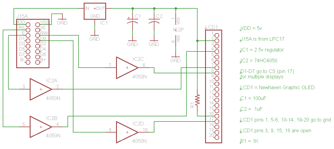
i improved the schem so it makes sense for a 2nd display. if any more are necessary, i can draw it. a third could still be connected to this chip, but after that another 74hc4050 would be needed. i also can now verify that this works, since i have the voxel demo running on my display 1! :) ultra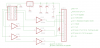
-
MIOS32 Voxel Space Graphics Demo on 256x64 Graphical OLED
ultra replied to Hawkeye's topic in MIOS toy of the week
i didn't draw it in, but of course if your'e connecting a 2nd lcd to d1, use additonal i/o on that chip. 11/12, 14/15, etc. you'd probably figured it out but i was just wiring it up and thinking about what i forgot. -
MIOS32 Voxel Space Graphics Demo on 256x64 Graphical OLED
ultra replied to Hawkeye's topic in MIOS toy of the week
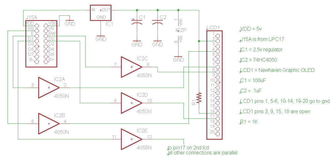
ok, i have what i believe will be a working schem for multiple newhaven graphic OLEDs. i'll test it later today, but i figured i should put it here in case someone wants to review it in the meantime. i based this off of tk's SSD1306 wiring diagrams at ucapps. the diagram for a single OLED is here and the diagram for multiple displays is here. the only question i really has is if the connections for multiple displays is supposed to correspond to the connections for single displays. if that is the case (which i think it is), then i've pulled up the /RS lines to 2.5v with a 1K resistor. if not, then the /RS lines go to RS on the core. but that wouldn't make sense as it's being used for DC. i'll chime in later on this if i get it working.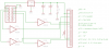
-
MIOS32 Voxel Space Graphics Demo on 256x64 Graphical OLED
ultra replied to Hawkeye's topic in MIOS toy of the week
i did some research and i found the 74hc4050. it'll convert a higher voltage to whatever voltage you power it with, as far as i can tell. so i ordered some of those and a couple 2.5v regulators. so a 16 pin chip, a vreg, and two caps should solve the problem. i can't figure out why, but sometimes the voxel demo works just fine, and other times the display won't turn on at all. and the core flashes the led 3 times and shuts off when it's not working. i think it's maybe current draw and hopefully the 4050 solves the problem. i'll post a schematic when i put it together later this week. ultra edit: also i wanna add that i didn't use any caps when i was testing it on a breadboard, and it didn't seem to flicker. weird. -
MIOS32 Voxel Space Graphics Demo on 256x64 Graphical OLED
ultra replied to Hawkeye's topic in MIOS toy of the week
hawkeye, do you remember if you used 2.5v on the data lines? i got an LM317 for power now, and that's working fine. but occasionally this thing isn't working, and i think it's b/c of the current draw from the resistor dividers i'm using for the data. maybe i won't kill the lcd if i connect those directly to the core? ultra -
looking at the pcb from the top, midi jacks to the bottom of the screen, here are the x/y coordinates: bottom-left hole: .234", .805" bottom-right hole: 3.801", .805" top-left hole: .178", 3.31" top-right hole: 4.568", 3.31" these are using the very bottom left corner of the pcb as the origin. a couple things: you can get these values yourself by installing the free altium viewer. just double click the hole to get a properties window. the x/y origin on the pcb in altium is not at the bottom-left. it's offset by a little. something to take note of if you do get the values yourself. i found it to be offset by .06" (x) and .16" (y). my values are based on the actual corner of the pcb. i put them into catia, which converted from mm to inches and rounded to the thousandth of an inch. i got these values to line up nicely by printing my catia drawing to a transparency and checking it against a printout of the pcb from altium, but i haven't verified it yet with a completed design. i recommend that you find the values the same way i did. get the x/y and add in the offset of the origin. ultra
-
i finally remembered to check on this, but it looks like you guys figured it out. mine didn't run b/c my mini isn' t intel.
-
i have an old mac mini sitting around with leopard on it. i'll see if i can get mios studio 2 to run when i get home in a few hours.
-
ableton live clip trigger device is almost done being designed (for real this time). and i have a lot of nifty code written for the next device too. :)
-
[SOLVED need help connecting newhaven oled
ultra replied to ultra's topic in Testing/Troubleshooting
issue was resolved in the chat with nils. i'd give the answer but i actually dont' know it... it suddenly decided to start working on its own. -
i'm trying to connect a newhaven nhd-2.8-2.5664ucb2 display (datasheet). to get my 2.5v, i'm using a 10r/33r resistor voltage divider. after voltage loss on the ribbon cable to the breadboard, i have 3.27v from the core. so taking voltage off the 33r resistor (i think later i'll use a resistor/zener combination for efficiency) gives me 2.51v. perfect. that also leaves me with 76mA of current available, so there should be enough to power the display. for wiring, i used the ssd1306 wiring diagram at ucapps. i think the pins match up enough to be fairly obvious, but my connections may be wrong. here is how i have the display connected: (edit: except for vdd/vss, i replaced all resistor dividers with 1k/330r) 1 VSS - lpc17 ground 2 VDD - lpc17 VDD (2.5v from 33r resistor) 3 NC - not connected 4 D/C - RS on lpc17 (2.5v from 33r resistor) 5-6 VSS - lpc17 ground 7 SCLK - E on lpc17 (2.5v from 33r resistor) 8 SDIN - RW on lpc17 (2.5v from 33r resistor) 9 NC - not connected 10-14 - lpc17 ground 15 NC - not connected 16 /RES - to VDD/2.5v via a 1K (this pin is active low) 17 /CS - D0 on lpc17 (2.5v from 33r resistor) 18 NC - not connected 19 BS1 - lpc17 ground 20 BS0 - lpc17 ground i compiled and uploaded the sd1322 demonstration app from the repository. without the display connected, the core functions normally (led blinks a few times and i can still upload). with the display connected, the lpc17's led blinks endlessly and i can't upload anything. the core is locked up. any ideas would be appreciated! ultra
-
MIOS32 Voxel Space Graphics Demo on 256x64 Graphical OLED
ultra replied to Hawkeye's topic in MIOS toy of the week
nm i think i figured it out :) -
MIOS32 Voxel Space Graphics Demo on 256x64 Graphical OLED
ultra replied to Hawkeye's topic in MIOS toy of the week
i have a pair of these arriving today! can someone plz tell me how to connect them to a lpc17? ultra -
writing heaps of liveapi code
- Show previous comments 4 more
-

A new pattern mode interface, that is intend to control ableton from midibox, using liveapi. I am working rigth now on the interface concept and doing some tests with it. The main goal of the new pattern interface is to get you mix track patterns quickly(not the old way, something more like a Yamaha RM1X), with preview data of your patterns, so in one LCD you could view whats playing, in the other LCD you could view and navigate trhu your patterns to select the next to be played. also integra...
-
-