

synthesizerbauen
-
Posts
13 -
Joined
-
Last visited
synthesizerbauen's Achievements
MIDIbox Newbie (1/4)
0
Reputation
-
dinx1 DINX1 on MIOS8 no load signal on RC-line?
synthesizerbauen replied to synthesizerbauen's topic in Testing/Troubleshooting
OK, ripping everything apart now and put it together tidy. But I have a suspicion: which side (PIN) of DINX1 should go to to the core: PIN9 (QH) or PIN10 (SER)? I had it connected to PIN10 (SER) and while ripping apart it dawned upon me, this was the wrong side... Will be reporting back with pictures... Thanks for your help! It's always best to have someone helping you out, when you're stuck and can't bring up new motivation. -
dinx1 DINX1 on MIOS8 no load signal on RC-line?
synthesizerbauen replied to synthesizerbauen's topic in Testing/Troubleshooting
It's an 8Bit PIC-Core. And I've already checked for continuity to the RC-Pin, its good. The DIN-Test with the MIOS-App "srio_interconnection_test_v2a" gives me exactly what is supposed. I also get that RC-pulse now, according to my oscilloscope. One Button had a strange behaviour, so I disconnected it, nothing changed. Strange behaviour was this: when I hit the button the voltage would go low, but then slowly up again, albeit beeing still pressed. That's the thing: I've done every test there is and all pass. It's a mystery to me. But now that I can see the pulse I'm sure it m u s t be my dinx1 implementation. At least something! -
dinx1 DINX1 on MIOS8 no load signal on RC-line?
synthesizerbauen replied to synthesizerbauen's topic in Testing/Troubleshooting
Do you mean another MIOS app? tested SIO (Serial Input Output) with "srio_interconnection_test_v2a" -works- all Pins get pulled low as should be. But this one is interesting: connecting serial clock to serial out on DINX1 module (for faking input) gives note and cc messages -works- So basically the PIC can read from the shift register, it just so seems, that none of the inputs do anything. Also I don't notice any activity on Pin1 (LD), even with 250ns resolution, is that OK? I will try setting "debug on", waht can I expect? Debug screen messages? -
dinx1 DINX1 on MIOS8 no load signal on RC-line?
synthesizerbauen replied to synthesizerbauen's topic in Testing/Troubleshooting
Thank you for your time. Pin15 (CLI) is indeed connected to ground (which dont't fully understand, because in an Arduino implementation, that pin is used for communication). Pin7 (QH#) is open. Pin9 (QH) is open, as it is din1X and not connected to other shift registers. I used 10k pullup resistors to 5V. When I press any of the buttons or use the encoder, the appropiate Inputs are pulled low (to ground). I've also checked several times, that all is wired according to 'mphp_din1X.pdf' I noticed, that there is a setting in the firmware for how many shift registers there are (set to 9). I set this to 1, just for good measure, but to no avail. So I set it back to 9 again. In have the toolchain to compile the whole thing to hex, so if I should change anything, I can. Thanks again. -
dinx1 DINX1 on MIOS8 no load signal on RC-line?
synthesizerbauen replied to synthesizerbauen's topic in Testing/Troubleshooting
I've already checked everything in the wiki btw. Nothing helped. No one? -
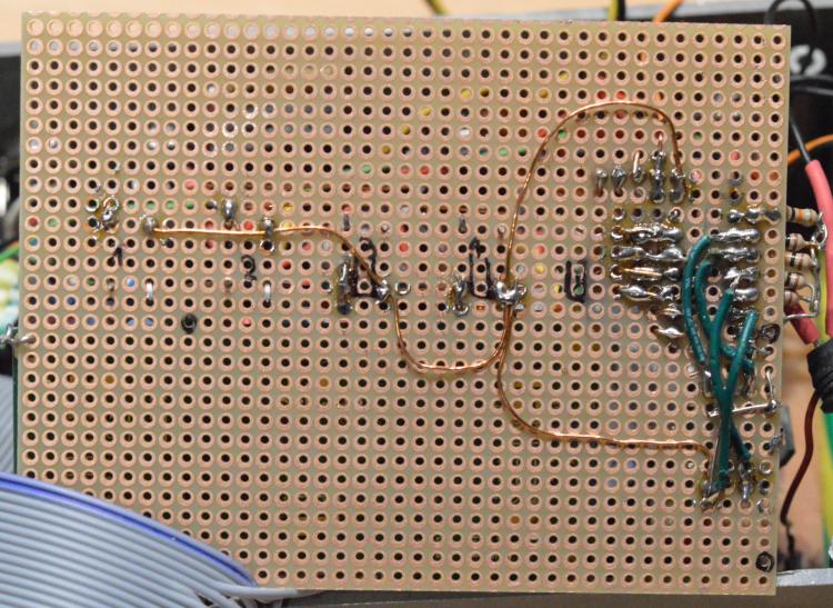
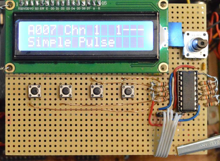
Hello all, have been troubleshooting this for hours, and need your help. Scenario: running PIC18460 Core V3 with 16x2 lcd display, running mios 1.9h -works- uploading of apps -works- midibox_sid_v1_7303e with 24LC512 bank stick -works- connected SID module -works- tested SIO (Serial Input Output) with "srio_interconnection_test_v2a" -works- activated CS in setup file "setup_8580.asm" build DINX1 on verobaord checked pulldown of all DIN-Pins with multimeter -works- checked serial clock witch oscilloscope -works- uploaded "midio128_v2_2c" pressing connected buttons for sending midi-notes -doesnt work- X connecting serial clock to serial out on DINX1 module (for faking input) gives note and cc messages -works- tested 74HC165 in another device (not MIDIbox) -works- swapped PIC18460 -doesn't work- X checked RC-line (i.e. load pin of 74HC165 = pin1) with oscilloscope in 250ns resolution: line is always 5V -???? X checked for shorts, every permutation -none found- I've checked the connections on the DINx1 dozens of times. It seems to be all good. Question: for a control surface A (4 buttons + 1 encoder, with button, DINX1) with 16x2 lcd, is there anything specific I have to do in the code? It still could be the veroboard build of the dinx1, but i doubt that. See attached pics. Any help is very appreciated. SB
-
I just wanted to file, that I successfully build the newest version of JSynthLib on Mac OsX 10.9 Mavericks, it even runs in multiple instances. I build it with intellij IDEA 16.2 and Java JDK 1.8.0.111 using Maven as the build,package tool. I tested it with some units and everything works just fine. For those still using it, or needing an editor for the SIDbox V1 (like me) on Mac OSX, here it is as exectuable jar. I hope this sticks to the GNU rules uploading it here. It's build from following source:Tree [a4a9e3] https://sourceforge.net/p/jsynthlib/jsynthlib/ci/master/tree/ .. You will need Mac OSX JAVA Version 1.8.0.111 form ORACLE: http://www.oracle.com/technetwork/java/javase/downloads/jdk8-downloads-2133151.html .. I tested it on two Macs, with OSX 10.9 Mavericks and 10.11 El Capitan. IMPORTANT: There seems to be no way to upload zip,rar or jar files here. So here's a dropbox with the JAR for Mac OSX: https://www.dropbox.com/s/qf45zpk80gc9pxs/jsynthlib-1.1-SNAPSHOT-executable.jar?dl=0 .. Have fun editing! I have done a branch of an older version, beautifying the gui and implementing : * M1 driver (but no editor) * ESQ-1 driver update, so that it can actually get and store Patches automatically (but no editor) If someone is interested, I can dropbox this too. Cheers
-
Wow! *double up* Alright! - Thank you. I get confused sometimes by the v1 and v2 Midibox Sid Revisions. Now then again i can use that in jsynthlib (overhauling it a bit on a mac, nicer buttons and such) to switch banks, that's great news. Ah - btw. I have done a decent control surface patch (not all functions of mbsid impolemented,though) for a clavia nord modular g2(+exp board). Where could I upload it, if someone is interested? Cheers, copes
-
Hello there, i recently fixed my mbsid (mios1.9f and sid v1.7303e, both compiled for 18F4620). And recompiled the sidapp, so the LC512 bankstick is now supported. What I read is, that in this sidapp there's only 128 possible patches per bankstick (as there are only 128 program changes 0xC0). When I switch on my mbsid, I hear the rising sound (meaning found bankstick) TWO times. In contrast in the old config (in setup_8580_without_cs.asm), running the LC512 as LC256 I only got ONE rising sound. Does that mean I have double the space now or two patch banks? BTW: I know that bankstick addressation is hardcoded via GND/+5V on Pins 1,2,3 of the LC256/LC512 And related question to that is (have been peeking around, but then again got a little confused): How to change access to banksticks in mbsid (v1.7/mios1.9) via MIDI, i.e. BankChange or sysex. Many thanks, copes
-
MB SID very low output, hanging notes, PSU problems
synthesizerbauen replied to synthesizerbauen's topic in MIDIbox SID
Hello everyone! The worst issues ARE SOLVED !!! yipi kay ye! The sound is loud and clear, and the note-events are doing their thing! Solution: One time I've experimented with a different power supply. That thing ripped off my pic. It didn't display anything on the lcd anymore (but apart from that worked fine....). I guess that was the point, when the Voltage Regulator 7809 on the sid v2 pcb was also damaged. Fortunatly I've made the 7809 pluggable. I tried another one (actually 7808, but hey..) And that solved both issues: low volume AND the note off problem. (Well if the poor sid doesn't get enough voltage, it obviously can't pay proper attention) As Thorsten said, I checked the cap c3 on the sid pcb first, seemed to be ok. Checked the whole area around the amp circuit, also ok. Changing the 7809 solved it! But relating to the 3rd problem (see earlier post): If core and sid pcb are connected to the psu, and I switch the power on, the core won't boot up. Not even the lcd backlight goes on.... could that be a bad filtering cap? (Measured them, ok). I've used a graetz bridge from an old c64, will check that also. btw, I mentioned a funny thing while testing: As I have an isa hardSid, I test my sids there first. One of them seemed to be totally bend when using the hardsid, but within the mb sid ist worked quite well... So thanks again, Cheers! sB -
MB SID very low output, hanging notes, PSU problems
synthesizerbauen replied to synthesizerbauen's topic in MIDIbox SID
Wow, that was fast! thorsten wrote: Note Off issue: MBSID can handle both, Note Off and Note On with velocity 0 - so, it would be interesting if the core really receives all Note Events. I would propose to upload the midimon application, it displays the received events - results? Hello Thorsten, I've uploaded midimon and used ableton5.2 as sequencer. When I start the clip, at first it gets 2 times cc123 #0 And the repeatedly note-on #99, and at the end of note-on #0, So this seems to be fine.... It'll take a bit to check the pcb, back later.. @stryd_one ok, got that ;) -
Hi there, so this is it, my first post... This forum and all the ucapps content have been of great value in understanding and building the mbbox sid project! Thanks to all for that first. But at the time I'm stuck and haven't found a solution to the problem, so I start this one. I've build the basic Core-Sid setup for 8580 with pcb core v3 and pcb sid v2. I am using the latest v1.7 engine. with mios v1.9f. all tests passed and as I said I was able to install the sid app. I can change the patches (bankstick installed, lcd responds) via program change. Until here everthing's fine and dandy. Now here are the issues, which are really seperated from another, I guess. 1 I can play all patches and they sound ok, BUT all notes are hanging. That means they play in a legato style. Checked the output of my sequencers and they either issue note-off or note-on with velocity 0. Seems to be ok. As everything else with MIDI works, I'm a bit confused. Already checked another optocoupler, with same results. All SID Interconnection Tests pass A OK. 2 The output volume is very very low. That means I have to crank it up like 70db to hear the sid. Naturally the SNR isn't in the range of usability. But at least I get output Tried s.th. with a function generator (actually an APC). When I inject the signal of the apc at the point where the sid chip output is it, too, is very very quiet. If I inject the Signal at a later point the signal is loud and clear... Tried to bridge the output of the sid to tht later point, but to no avail (no sound). I tested the the transistor and its readings are ok. 3 An maybe that has something to do with everything else...the PSU. I use the optimized C64 PSU circuit (v2). I get correct voltage readings, when no IC is inserted and basically my setup works but: When I power on the PSU nothing happens. I have to detach the SID module from the 14v line and then the core powers on and mios boots. Thereafter I can put in the SID modue supply. So far so good. As I have many of the c64 psu's I tried several of them and all gave the same result. Can someone please help with this one? I've been unable to find a matching solution... Greetings to all midiboxers, sB
-
Yes, that would be the professional way, but If you want a quick affordable solution, go for a used Yamah dd11 and put it into another case (but you needn't) here's the link (in german), but the pictures say it all. http://robotporn.de/2007/01/08/cheap-diy-drum-trigger-converter-the-triggerlution/ Cheers, Synthesizerbauer (in spe)

