

wackazong
-
Posts
298 -
Joined
-
Last visited
-
Days Won
1
wackazong's Achievements
MIDIbox Tweaker (3/4)
3
Reputation
-
I did some tests today on this topic. I had very good success by simply debouncing the encoders with two caps of 0.1uF between the common pin and the output pins. This can even be done on the encoders pins themselves, no need to change the PCB. Now I have not had a single bounce so far during my tests. Seems to work and is simple enough for me to do in hardware.
-
Hello again, I would like to do some kind of software debouncing for my encoders. I have them at DETENTED3 and FAST 2 now, this gives the right frequency and step size of value changes in relation to the turning velocity. However, the introduction of FAST mode brings a problem: when the encoder bounces, the value suddenly moves very fast, as the algorithm notices very rapid value changes in the SRIO chain, then applies acceleration and generates a big value jump. Is it possible to debounce the encoders? I can see in the code that only buttons are debounced now. I was wondering whether there is some way to activate it for encoders. Thanks! Ander.
-
Yes, Station is already updated :)
-
Wow, much better! I like the new feeling very much. Thanks for that. For me speed_par 1 is best. Almost full 360 degree turn when I turn fast. As most of my encoders are set to the middle value and I deviate from that, this is enough for me. A tad slower even could be nice, but this is already a big improvement.
-
Well.... I just finished my own Midibox, now a friend wants one, too :) I would like to teach him, although he has never soldered or programmed before. Will be interesting. He is looking for a relatively simple Midibox 64E kind of thing, but he wants LED rings. Is there an existing PCB layout for LED rings which he could use? I searched forum and Wiki but could not find anything.
-
MIDIbox of the Week: Station MIDI controller by Ander
wackazong replied to TK.'s topic in MIDIbox of the Week
Thanks :) Was not really easy... 1) Record video and audio 2) sync both in Ableton live 3) render snippets which are multiples of 8 or four bars, add some overhead on both sides 4) manually do the camera changes in iMovie using the "precision" editor -
MIDIbox of the Week: Station MIDI controller by Ander
wackazong replied to TK.'s topic in MIDIbox of the Week
The encoders are standard Bourns PEC11, no special quality there. I did not find any suitable SMD encoders, so for theses parts I had to put some holes into the PCB. This makes it more rugged, so maybe it was a good decision after all. The push buttons are standard SMD pushbuttons, I needed some with very low actuation force, therefore I took the DTSM-65K-V-B from Diptronics. No surprises here, theses parts would work in a normal midibox without problems. -
MIDIbox of the Week: Station MIDI controller by Ander
wackazong replied to TK.'s topic in MIDIbox of the Week
Yeah, the routing was difficult. I did it with kicad, it took me i think about 5 attempts. Regarding your questions: 1) yes, correct. White soldermask is just a tiny bit more expensive than green at http://www.multipcb.de/. I can really recommend them by the way. 2) I don't get that, sorry. I have all module connected in one row, therefore there is one input and one output on each PCB. It connects the DIN and the I2C bus (for the LEDs) 3) No, 0.125W would not be enough. Each array drives 16 LEDs. Unfortunaltely, the PC!9635 requires resistors, I would have liked a part with constant current regulator, but I did not find one that suited me. 4) Yes, they determine the I2C address of the driver chip, which has to be different for each chip. There are three on each PCB, one for each color. 5) Yes, more or less. one signal layer, one ground layer, a mixed power/additional PWM layer and one layer only for PWM (of the LEDs) -
MIDIbox of the Week: Station MIDI controller by Ander
wackazong replied to TK.'s topic in MIDIbox of the Week
Yes, I use Ableton Live for music production. -
MIDIbox of the Week: Station MIDI controller by Ander
wackazong replied to TK.'s topic in MIDIbox of the Week
Well spotted ;) Your are right, the PCB is the same for all modules. It can hold either one encoder or two pushbuttons in the same area, or any kind of sensor with analog output. One PCB can hold 16 pushbuttons or 8 encoders/sensors, or any combination. Actually, one module consists of all the necessary PCB stuff for - one STM32 core - 2 DINs (in a SMD version) - one step down converter (24V to 5V) - three driver chips to drive 16 RGB LEDs (PCA9635). This is a design of my own, I do not use DOUT modules The core parts are of course not soldered in on every module, but of course this one PCB design made developing and producing the PCB much cheaper. Its actually 4 Layers, 16 RGB LEDs need quite a lot of routing... -
MIDIbox of the Week: Station MIDI controller by Ander
wackazong replied to TK.'s topic in MIDIbox of the Week
Thanks Wilba for posting the pictures. BTW, this was all hand-soldered by me.... Very meditative. I have made a quick drawing of the button mechanism. It works quite well, you can push on it everywhere on the surface and it activates the button. I selected a pushbutton with only 150g of force.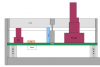
-
MIDIbox of the Week: Station MIDI controller by Ander
wackazong replied to TK.'s topic in MIDIbox of the Week
While I am at it: Many thanks to you for supporting me during this project. I could not have done it without the help of you and the great MBHP. I will try to post some photos, source and docs here in due course. -
MIDIbox of theWeek (Traktor Controller by Rogic)
wackazong replied to TK.'s topic in MIDIbox of the Week
The website seems to be down, anyone have the photos so we can host them somewhere else? -
MIDIbox of the Week: Station MIDI controller by Ander
wackazong replied to TK.'s topic in MIDIbox of the Week
Hi, regarding the buttons: Its an acrylic button I had made for me, 6mm of opaque acrylic plastic. It fits directly into the case and is secured by a small notch so it cannot fall out. One side is supported by a small piece of elastic foam, the other side has the pushbutton below it, so that the led can sit in the middle. Quite simplistic, actually, but it works very well so far. Next time I would put notches on both sides and tink MUCH more about the mechanics before building them, but as long as it works now I am happy :).


