

latigid on
-
Posts
2,524 -
Joined
-
Last visited
-
Days Won
149
Content Type
Profiles
Forums
Blogs
Gallery
Posts posted by latigid on
-
-
Also ich bin ein Klugscheisser mit einem riesigen Eisenpenis! :w00t:
Ich war sagen wird, vergest du nicht Großbuchstaben für Nomen!
-
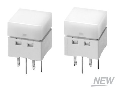
Of course, the Omron switches are waaaay too expensive. :)
I realise the SMD LEDs would be too short, but then could lower profile (shorter) tact switches be used as well? Or is the idea to mount other components (e.g. encoders) on the same board?
-
Anyone remember these guys?

Graham's is better though ;)
-
The next question is whether SMD is okay?

I tried searching for clear RG LEDs through hole; nothing jumping out at me.
-
I'm in, but were you thinking about a PCB to make soldering life a little easier? :ahappy:
Of course, these would be "easier":

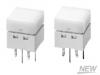
http://www.omron.com/ecb/products/pdf/en-b3w-9.pdf
, but at ~2.20US each, TK's idea is more affordable
http://mouser.com/ProductDetail/Omron/B3W-9000-RG2N/?qs=EHIUIbu4VmgJJhoE/NFbUA==
Edit:
Price breaks if interested:
1: $2.68
25: $2.39
50: $2.32
100: $2.20
250: $2.11
500: $1.96
1,000: $1.77
-
POIDH :shifty:
-
Not necessarily cutting out the whole case, just where there are holes (encoders, buttons, LEDs, LCDs might be a bit trickier).
That way your blind panel can be a bit rough or drilled with enlarged holes etc.
It might even be a good way of getting a dual-use case, as you could then enlarge the FPE panel to 19" format :question:
Sorry, just thinking out loud
-
Although there would be a few "mils" of extra aluminium, one way to do it might be to get a nice panel from FPE and just drill the case yourself.
Might work out a bit cheaper?
-
I don't know what it is... but it looks interesting!
Yamaha QY-70
-
-
If I understand "Series Capacitor".. that would pass AC but block DC..
Since it's a DC fan, I'm guessing that wouldn't help much.
But I may be misunderstanding you.. :)
LyleHaze
Ehh, yeah, I'm thinking of an AC motor. Please ignore :blink:
-
I'm probably wrong, but can't you add a series capacitor to get motors cranking?
But I agree; using some unregulated voltage is a good idea. You could even add a resistor to control the speed (noise).
-
I've got one of these:

Very handy!
-
Thanks TK
I just ended up using another computer :whistle:
Btw, on windows my USB MIDI port is called "USB Audio Device" not MIOS32 or something (?)
Anyway, Core32 done.
Now where did I put my SEQ CS? :)
-
It is big, but things like this have been done before.
Seeing as you mention "survey"ing I might add that encoders are not visual unless you put LED rings around them. Analog pots are, but there's no way to store their positions. It all depends on what you would like to do.
I would agree with Wilba; a large project like this would probably take a _long_ time and wear you down unless you had a tremendous amount of spirit. But welcome anyway, it sounds like you're in the right place.
-
I was putting together my Core32 board last night, following the instructions on uCApps. However, when it came to "activating" the MIDI port, I could not get Windows to find the MIDI port. The install goes okay; it finds a device called "MIOS32" then calls it a USB Audio Device (with a generic driver). However, when I go to find the MIDI ports in MIOS Studio, I cannot find them. I was searching through the MIDIBox forum and found a few links (some in the Spanish section!) to other forums (PIC forum etc.) where they tell you to delete registry filters etc.. I did try this, but still could not get it to work. Presumably there is some conflict between other devices on my system?
Any ideas? Or am I stuck on enabling the Boot Hold and uploading via regular MIDI? Or using another OS like MacOS or Linux?
Thanks
Andy
-
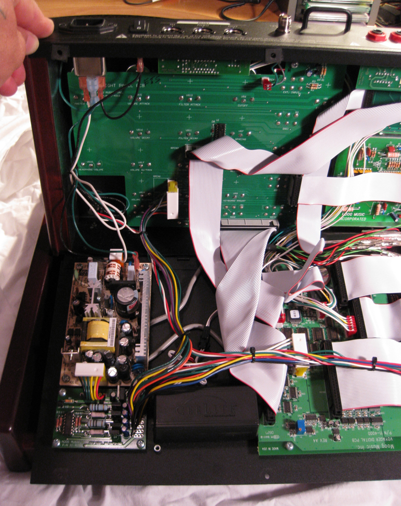
Do you have to get high quality inverter or something to get rid of hum? .
I know they offered a "Quiet II Upgrade". You can see the inverter circuits in later models (Version 3 hardware)
(Not my image --> link
-
In was looking up some perf board and came across this site
http://www.allelectronics.com/make-a-store/category/213/Electroluminescent-Strips/1.html
with some used el lighting for only $1 US each.They light up green already. Would this change the color scheme when used with you gold text do you think? They have new ones for $3.50 and $4.50 plus discounts on bigger orders. Can this stuff be cut and soldered back together to get longer lenghts?
Regards,
echo
Because the yellow/gold letters are turning green, it actually means they are absorbing RED light and this lets the remaining GREEN light pass through. So using green backlights will probably work differently.
My Moog Voyager has a backlit panel 8), and with the intensity turned all the way up it hums pretty badly. Thankfully it doesn't get into the audio, but there is the possibility it might for these sorts of things, as someone said.
-
I am curious how deep are your panels cut to do the lighting from behind? Is there a terminology for this type of panel marking/engraving? From what your saying, did you just get a panel cut that was black with gold text and you put a white light underneath the panel and you got light up green text? Would a particular metal work the best for light to leak through?
Regards,
echo
Metals are usually opaque... and he has "acrylic" in the title ;)
I don't really know of other plastics you would use for panels but it would depend on the material's refractive index, thickness and colour. It's hard to tell from his pictures, but it may be "smokey" acrylic which would transmit some light.
-
You could always try LED strips:

All the tracks are topside, so in theory you could somehow mount to the CS PCB. Probably the rigid ones are what you want.
-
Beer sometimes helps
There you go
-
nILS's next MIDIBox project and latest single:
-
Wilba's got mine, but that's something I'll have to nag him about ;)
Where's my eucalyptus stick when I need it?
Oh there it is
*whack*
-


Teaser for an upcomign project
in Miscellaneous
Posted · Edited by latigid on